HeaterMeter 4.1 Assembly
- Soldering Iron & Solder - I use 60/40 0.032” rosin core solder and an AOYUE 936 Soldering Station although even a cheapie soldering iron from Radio Shack should get the job done easily
- Diagonal wire cuttters
- A computer with an SD card reader
- OPTIONAL: Small Needle nose pliers
- Everything from the Mouser project $31
- Everything from DigiKey: 1xBlower 1xSocket 4xJacks $19
- A HeaterMeter v4.1 PCB - see below $15
- 12V 1A (or greater) power adapter with 2.1mm barrel jack (tip positive)
- HeaterMeter Probes minimum 1, up to 4 $10-15 ea
-
RaspberryPi
- Model A (no Ethernet, 1x USB) $25, or more accurately closer to $33 shipped
- Model B (with Wired Ethernet, 2x USB) $35, usually [closer to $45] (http://www.amazon.com/gp/product/B009SQQF9C/ref=as_li_ss_tl?ie=UTF8&camp=1789&creative=390957&creativeASIN=B009SQQF9C&linkCode=as2&tag=httpcapnbrnet-20) shipped
- Full sized SD card (not microSD or miniSD) 128MB or larger
- A WiFi Adapter based on rtl8192cu chipset Edimax EW-7811Un (optional) $11
- Phone or ethernet cable you won't mind cutting an end off of
- Some sort of fan-attaching mechanism for your grill
- Some sort of enclosure
This can be obtained either by finding someone who has an extra (they're usually ordered in 3s and you probably only need one) or by ordering your own set. To order your own set, use any online PCB fab service which supports gerber files. OSH Park is the preferred online service for the U.S., due to their quick turnaround, impeccable output, friendly service, and reasonable prices. Just upload the "dorkbot" zip file to their service and pay them. You'll have boards in your hands in about two weeks. PCB 4.1 Snapshot
OSH Park will soon have PCB board singles available in their store. OSH Park PCB 4.1 Singles (not yet available)
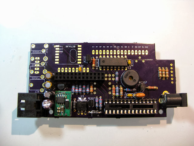
The HeaterMeter v4.1 PCB has two sides and components go on both sides. The silkscreen outlines indicate on which side components should be placed, but in general most of the components go on the underside of the board. The easiest way to assemble the board is to start with the flattest components and work your way to the larger pieces.
All directions in this section refer to the board being bottom side up. That is, the side that does not say "HeaterMeter 4.1" on it. The "RFM12B" marking should be furthest from you and the Pit/Food1/Food2/Food3 markings should be on the left.
Cut a piece off one one of your component leads and bend it to fit into the position marked "0" and solder it into place. This is a "0 ohm resistor" needed for the LCD backlight. If you did not use the recommended Newhaven Display LCD, you'd instead place the proper current-limiting resistor needed for your backlight here. The Newhaven model is nice in that the current-limiting resistor is integrated into the display itself.

Solder the rest of the resistors. The orientation on these does not matter either side can go in either hole, as long as the body of the resistor is on the right side of the board. The placements are sized such that you should be able to fold the leads of the resistor against the body at a right angle and have them just fit into the holes. It is easiest to insert a couple resistors at a time and flip the whole board over, resting the board on the resistors to hold them in place while you solder them and clip the extra leads off. When you're done soldering all the resistors, it should look like this.

Ceramic capacitors (small yellow blobs) Again, the orientation does not matter as these have no polarity.

The rectifier diodes have a white line on them to indicate their polarity and should be installed so their white line matches the white line marking on the PCB. Q3 (the fan driver MOSFET) should also be placed. To form its leads, just insert it into the holes and bend it down into position so it stays inside the component outline then flip the board and solder it into place. The tab can be soldered to the PCB for extra heatsinking, but it isn't required.

The tiny black water towers: 3x BC337 transistors and the MCP1700 3.3V regulator are installed next. The flat front of these should match the flat front on the silkscreen.

Then, solder the DIP-28 socket (IC2) and the DIP-16 74HC595 (IC3). Both of these parts have a notch on one side of them which indicates the direction they need to be placed. Do not install the ATmega328P chip into socket IC2 at this time.

Install the piezobuzzer (SP1) and 5V regulator sub-board (IC1), followed by the electrolytic capacitors. The capacitor "cans" have a line going down the side which indicates the negative side, the PCB has a teeny plus symbol to indicate the positive side. Use deductive reasoning to ascertain the correct orientation.

Install the 16MHz resonator (the larger yellow orange blob) in the unlabeled oval by the IC2 DIP socket, the orientation doesn't matter. Install the RaspberryPi GPIO header (2x13), the Phone/Ethernet jack, and the barrel power connector in their giant unmistakable footprints.
Install as many probe jacks as you'll have probes connected (JP3, JP4, JP5, JP6). We're now done with the bottom components.
Install R6 (LCD contrast adjustment potentiometer). Snap off 16 pins from the 36 pin header strip and install them in J1. Finally install the button into the large square position in the center of the board this has an orientation. Note the middle set of pins is closer to one side than the other. Put it in the way it is supposed to go in, not the way where you force it in because you thought it was symmetrical.

You might want to pause here. The LEDs and LCD may be easier to get their height right if you're soldering them in place while trial-fitting the system into a case.
When installing your LEDs (LED1, LED2, LED3) bear in mind that if you mount them flush with the board, they will be lower than the button and LCD face. You can either mount them with long leads, or mount them and bend them over to the left so they'd be exposed out the side of the case rather than on the front panel. The longer lead on the LED (the +/anode) is inserted into the hole closest to you. There's a little + sign to indicate this on LED1 but not the others, as that would get confusing with them all so close together.
The web UI has a red icon for LED1, yellow for LED2, green for LED3. Any arrangement can be used, but the web interface is fixed to displaying these colors.
XXX
The LCD can now be installed by soldering all 16 pins in place on the lower of the two connectors on the LCD itself. The LCD extends away from you and hangs off the board.
Do not populate J2 (PROBE), J6 (ICSP), or J8 (FTDI) unless you need them. These are provided for users who don't use the integrated connectors.
At this point you can install the ATmega328P into the DIP-28 socket IC2.
XXX YYY ZZZ
Ambient Temperature Thermistor A thermistor can be attached to one of the probe jacks to allow for ambient temperature measurement when a probe is not inserted into the jack. When looking at the board from the top, solder the thermistor between the far right pin and the close pin of the jack. Remember, the probe coefficients in the configuration need to be set for the proper probe type connected. That is, when you have no probe inserted the configuration should be set for the thermistor coefficients and when a probe is inserted they should be set to match the probe type. This modification can be seen on the Food3 jack here on a v4.0 board.
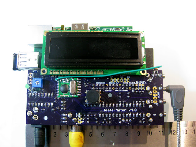
Wireless Probe Support HeaterMeter supports receiving ambient temperature from LaCrosse Technology IT+915 protocol weather stations as well as custom-built "lmremote" probe transmitters (although HeaterMeter is limited to four total probes wired+wireless). If this is desired, install a RFM12B transceiver board. The board is oriented so that the oval crystal on the RF board is over the oval drawing on the HeaterMeter PCB. A short piece (78mm) of insulated solid-core wire should be installed into the hole marked ANT as an antenna.
Remove the Raspberry Pi RCA composite video output jack by snipping it off where it meets the board. If you have the skills, it can be desoldered but after doing half a dozen of them I realized it wasn't worth the time. What are you going to connect it to, your 1995 CRT television?
Mount your HeaterMeter board onto the Raspberry Pi by mating the rPi's GPIO header with the HeaterMeter 13x2 socket. The HeaterMeter LCD is over the Raspberry Pi, power inpult on the left, probe jacks will be on the right.
XXX