HeaterMeter 4.3 Assembly
- Soldering Iron & Solder - I use 60/40 0.032” rosin core solder and an AOYUE 936 Soldering Station. Surprisingly good-for-the-price soldering stations can be found on eBay for ~$30 (search: 937D Soldering) and will work fine.
- Any Diagonal wire cuttters or genuine Xuron 170 flush cutters for cutting part leads
- A computer with an SD card reader
- OPTIONAL: Small Needle nose pliers

- Everything from the two Mouser projects Base and LCD/Button $58
- A set of HeaterMeter v4.3 PCBs - see below $19
- 12V 1A (or greater) power adapter with 2.1mm barrel jack (tip positive)
- HeaterMeter Probes minimum 1, up to 4 $10-15 ea
-
RaspberryPi
- Zero (no Ethernet, needs USB adapter for wifi) $5 if you can find one.
- Model A+ (no Ethernet) $25 $29 shipped
- Model B+ (with Wired Ethernet) $35, $45 shipped
- Model 2 B (with Ethernet, firmware v14 and above) ) $35 $38 shipped
- Model 3 B (Wifi/Ethernet, firmware v14 and above) ) $35 $38 shipped
- Model 3 B+ (Wifi/Ethernet, snapshot firmware) ) $35 $45 shipped
- Model Zero W (with Wifi, firmware v14 and above) ) $10 can be found at MicroCenter
- Micro sized SD card (not miniSD or full sized) 128MB or larger (Raspberry Pi SD Compatibility)
- A supported WiFi Adapter (Pi 3/3+ and Zero W include built-in adapters)
- Phone or Ethernet cable you won't mind cutting an end off of
- Some sort of fan-attaching mechanism for your grill
- Some sort of enclosure
There are two circuit boards (PCBs) needed to assemble the full HeaterMeter which can be sourced from your choice of locations. These can be obtained either by finding someone who has extra (they're usually ordered in 3s and you probably only need one) or by ordering your own set. To order your own set, use any online PCB fab service which supports gerber files. OSH Park is the preferred online service for the U.S., due to their quick turnaround, impeccable output, friendly service, and reasonable prices. Just upload the "Gerber" zip files to their service and pay them. You'll have boards in your hands in about two weeks.
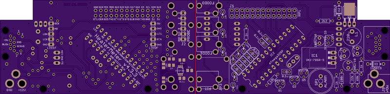
- OSH Park LCD/Button
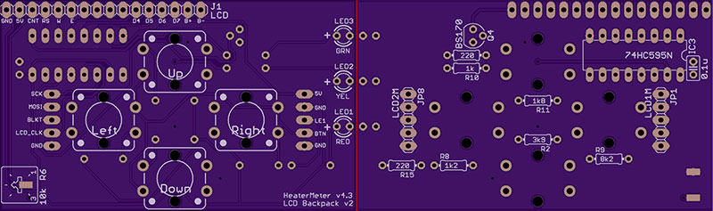
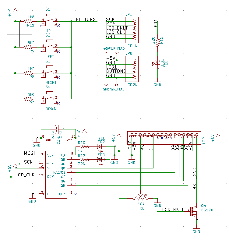
- Schematic Image Base and Button/LCD
- KiCad schematics and boards - Base and LCD folders
- OSH Park (Gerbers) Base and LCD/Button.
- Individual PCBs can be ordered from the Official HeaterMeter Store for both Thermocouple/Thermistor or Four Thermistor
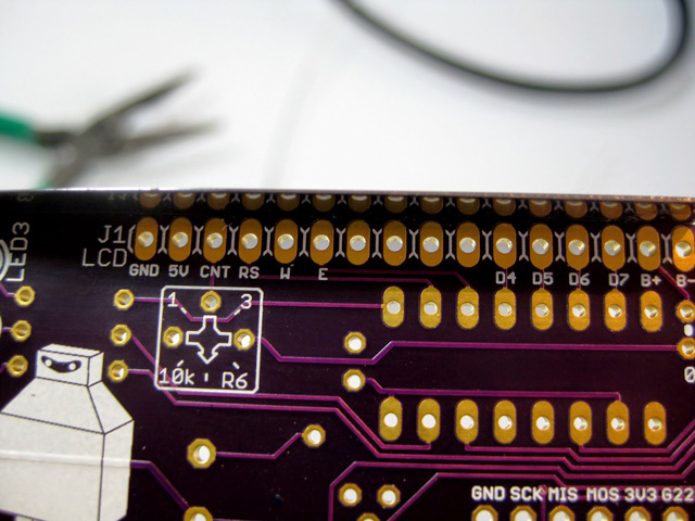
The PCBs may arrive with some scrap material around the edges where it has been de-panelized from other boards in the batch. In a few places, this excess material can cause clearance issues with the case so it is best to remove them prior to assembly.
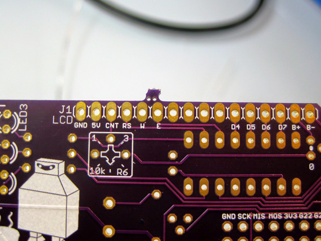
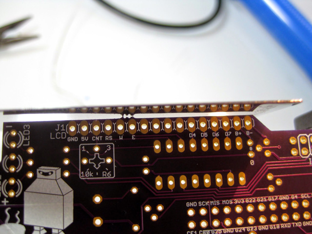
To remove the excess, simply snap off any of the larger bits with a pair of pliers then file or sand the edge lightly to smooth the area flat. An X-Acto knife or razor can also be used. The board material is pretty soft so this shouldn't take more than a few seconds.
Do this to all four edges of the board to prevent any issues down the road. Once the components are installed it is difficult to trim these bits without damaging the hardware.
Due to the modular nature of the parts, the build instructions are separated into multiple steps. All photos are available in the HeaterMeter v4.3 Assembly album although most refer to the 4.3.3 revision.
- Thermocouple SMD assembly and testing
- HeaterMeter 4.3 Base Board Assembly
- HeaterMeter 4.3 LCD/Buttton Board Assembly