EWCv3.3 Factory Configuration Procedure V104
[TOC]
This document covers the required firmware setup procedure for ESPEC Web Controller, Version 3.3.0 and later. This procedure must be completed on all ESPEC Web Controller (EWC) devices prior to shipment. Start with Section 1 and follow instructions through Section 4.
This section describes how to connect the EWC hardware, called Up2board, to a specific chamber and controller.
Communication interface between F4T and EWC is TCP/IP. Perform the following steps to complete the setup.
-
Plug the Ethernet cable into the Ethernet port labeled F4T, as shown in the following figure.
-
Plug the other end of the cable into the F4T Ethernet port (see diagram below).
-
Configure F4T Internal Network: Web Controller and F4T use internal network protocol for communication. Set the F4T network to a static configuration as follows. Note: This procedure is similar to our previous settings for our previous Web Controller.
-
Press Settings on F4T from the Main Menu.
-
Press Network then press Ethernet to access the IP address block.
-
Set IP Address Mode to Fixed.
-
Set the IP Fixed Address Part 1-4 as shown:
-
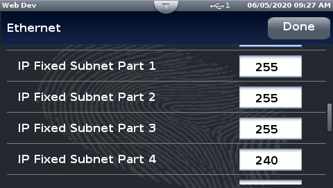
Set the IP Fixed Subnet Part 1-4 as shown:
-
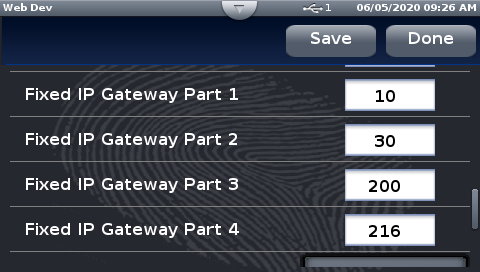
Set the IP Fixed Gateway Part 1-4 as shown:
NOTE: The Gateway IP setting can be left blank. The above configuration ensures that the internal gateway exists with a specific range between the Web Controller and F4T, starting with 216.
-
-
HDMI: The HDMI port is used to reference network Ethernet port. The two ports are adjacent to each other.
-
Network: This port connects directly to our main network. It is important that the Web Controller is connected to our main network so that the serial number can be registered properly, as described in Section 4. The HDMI port can be used to help locate this Ethernet port on the Up2board.
-
Press Save, press Done, and cycle power to the F4T.
-
Proceed to Section 2 (Flashing Firmware)


Communication interface between ESPEC Web Controller and P300, SCP220, ES102 and Watlow F4 is based on the standard serial RS-232/RS-485 communication port. P300 uses its standard RS-485 (5-pin) communication port. SCP-220, ES102 and F4 use RS-232 communication port. Note: F4T can be connected via RS-232/RS-485 interface if its ModbusRTU (Module 6) is used (and specified in the work order as a setup requirement). The jumper on the serial card of Up2board must be set for RS-232 or RS-485 as follows:
-
Jumper PIN Configuration for P300: Set the jumper on the serial card of Up2board for RS-485 as shown below.
-
Jumper PIN configuration for SCP220, ES102, F4: Set the jumper on the serial card of Up2board for RS-232 as shown below.
-
Proceed to Section 2 (Flashing Firmware)


The USB-to-Serial interface is the standard communication interface used on the U-Web kit. RS-232/RS-485 will be connected via the USB-to-serial, as depicted in the following figure.

-
Connect the USB-to-serial cable using any open USB port on the Up2board
-
Connect the serial cable to the USB-to-serial converter and connect the other end to the target chamber/controller
-
Proceed to Section 2 (Flashing Firmware)
The EWC firmware can be flashed onto the Up2board using the provided bootable USB media (depicted in the following figure). It is configured to flash the firmware automatically, which requires plugging in only the USB media followed by the power supply. This method flashes the firmware without a monitor or keyboard/mouse attached to the Up2board. Perform the following steps to flash the firmware.
-
Ensure that power is disconnected from the Up2board via the barrel jack.
-
Plug in the USB thumb drive into an open USB port on the Up2board.
-
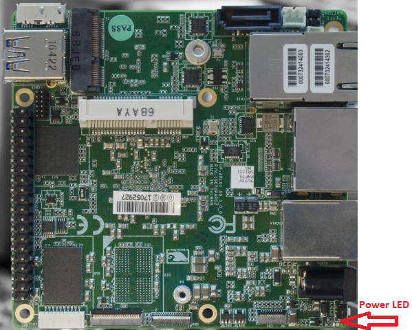
Apply power to the Up2board by plugging in the barrel jack. The blue LED (indicated by the arrow in the figure) will light up to indicate the Up2board is powered on. The system will boot from the USB and apply the firmware flashing.
-
Wait for the blue LED to turn off, which should take approximately five (5) minutes. If after 15 minutes the LED still remains on, there is likely a problem with the firmware flashing. Contact software engineering for assistance.
-
Disconnect power from the Up2board via the barrel jack.
-
Remove the USB thumb drive and plug in the USB dongle (see figure below).
-
Apply power to the Up2board by plugging in the barrel jack.
-
The system will start and the USB dongle will perform a BIOS configuration on the Up2Board for a proper startup.
-
The system reboots itself (twice) to check its configuration. The blue LED will blink and turn on and off twice. This process will require approximately three (3) minutes to complete.
-
With the blue LED remains on, remove the USB dongle.
-
The Web Controller is now accessible via a setup PC. Proceed with standard chamber configuration setup as outlined in Section 3 (below) for help to locate the Web Controller.


EWC can be accessed via its hostname or its IP address. Perform one of the following options to access your EWC.
-
Section 3.1 outlines the steps to access EWC via its hostname.
-
Section 3.2 outlines the steps to locate your EWC using the Web Controller Locator Utility.
-
Section 3.3 outlines the steps to access your EWC via its fallback IP address (192.168.0.83). This method allows you to connect the chamber and assign the serial number to generate a hostname. After your EWC reconnects to our main network, your can access it via its hostname to complete the registration.
This is the most direct method to access EWC via its default hostname.
-
On your setup PC, open a Web browser and enter:
-
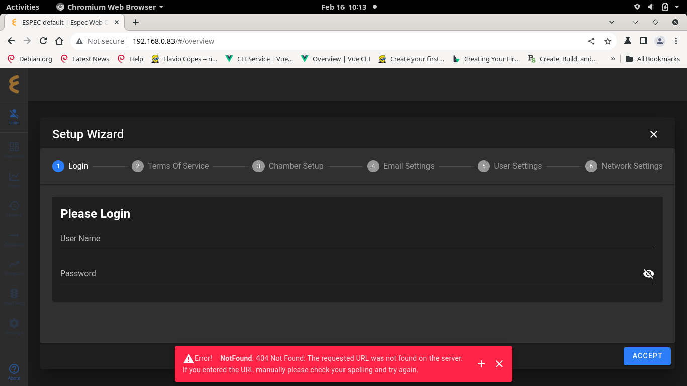
If successful, EWC displays its Setup Wizard as shown below:
-
If the web page displays an overview of EWC showing the status of the chamber, different from the above figure, then this EWC has already been configured by someone else (on the production floor).
-
Try accessing your EWC again with the following hostname:
and confirm that it displays its setup page as depicted in the figure at Step 2. Proceed to Section 4 to complete the Setup Wizard and chamber configuration. Otherwise, try the next default number, such as:
-
If the above attempt still fails, your EWC may not be on the network or has not started up properly. Proceed to Section 3.2 to attempt to access it via the Web Controller Locator Utility, or contact software engineering team for assistance.

When EWC starts up and joins the main network, its IP address gets picked up by the Locator Utility within a few minutes. The following figure depicts a typical list of all EWC found by Web Controller Locator Utility.

-
Launch Web Controller Locator Utility on your PC
-
Search for espec-default.local or espec-default-2.local on the list (shown by the arrow in the above figure).
-
Click espec-default.local or espec-default-2.local on the list to access your EWC. Proceed to Section 4 to complete the Setup Wizard and chamber configuration.
-
If espec-default.local or espec-default-2.local, etc., is not on the list, your EWC is not on the network or may not start up properly. Contact software engineering team for assistance.
This method provides a means to access EWC via its fallback IP address (192.168.0.83) to perform only the chamber configuration and assign hostname with the chamber serial number (Phase 1). We then power down the system, reconnect EWC to the main network (Phase 2). The purpose is to set up a hostname so that we can find it on the main network as opposed to the procedure in Section 3.2.
Once EWC is on the main network, you can access it via its hostname ``http://especSN.local/'' (where SN is the chamber serial number) to complete the registration.

-
Connect the Ethernet cable between the Web Controller and your PC (see above Figure).
-
Configure a static network on your PC with IP address: 192.168.0.84. Refer to Appendix C for detail.
-
Apply power to the Web Controller (and chamber).
-
Open a Web Browser on your PC and enter:
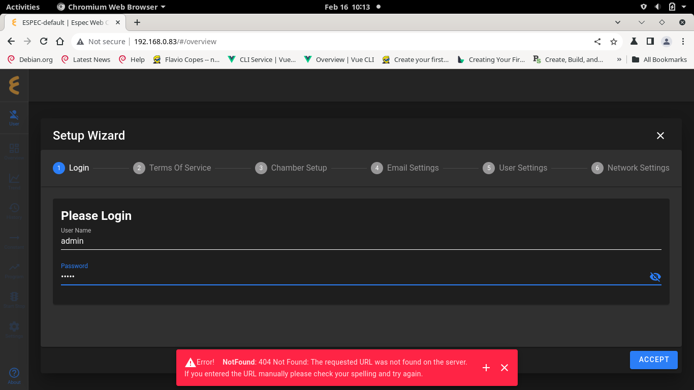
The Setup Wizard of EWC appears as depicted in the figure below. Note: Ignore the error message at the bottom of the page.
-
Log in: Log in using admin/admin
-
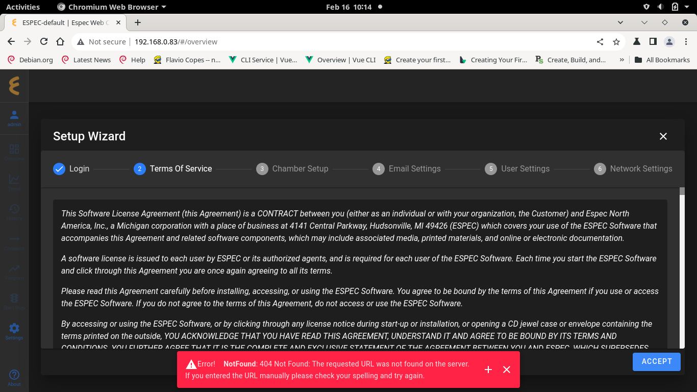
Terms of Services: Click ACCEPT to continue.
-
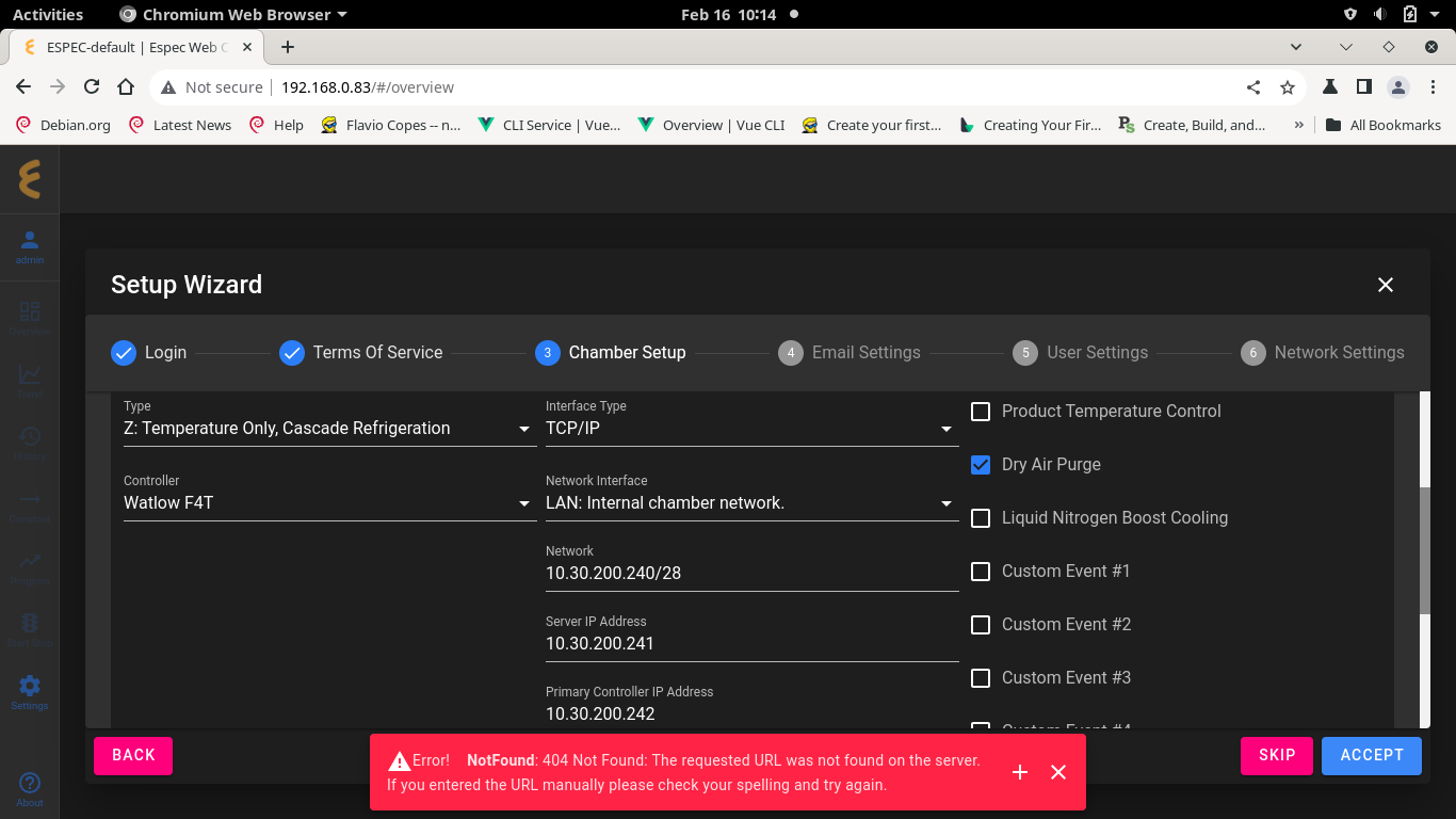
Chamber Setup: Perform chamber configuration based on the job description. Benchtop with Watlow F4T configuration is depicted as an example. Click ACCEPT to continue.
-
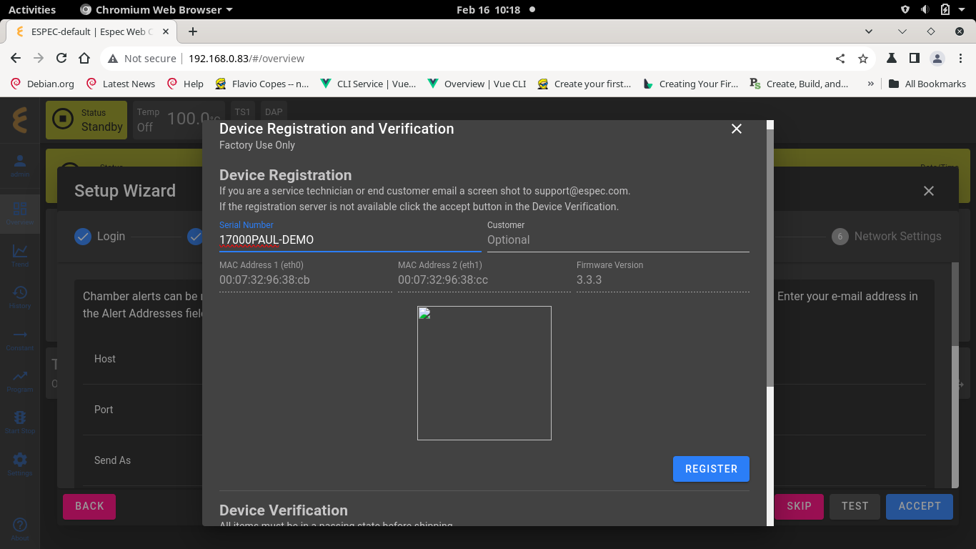
Serial Number and Registration: Click the Serial Number field and enter the chamber serial number (see Figure). Customer name (optional) can be entered as well. Click REGISTER to continue (see Figure).
-
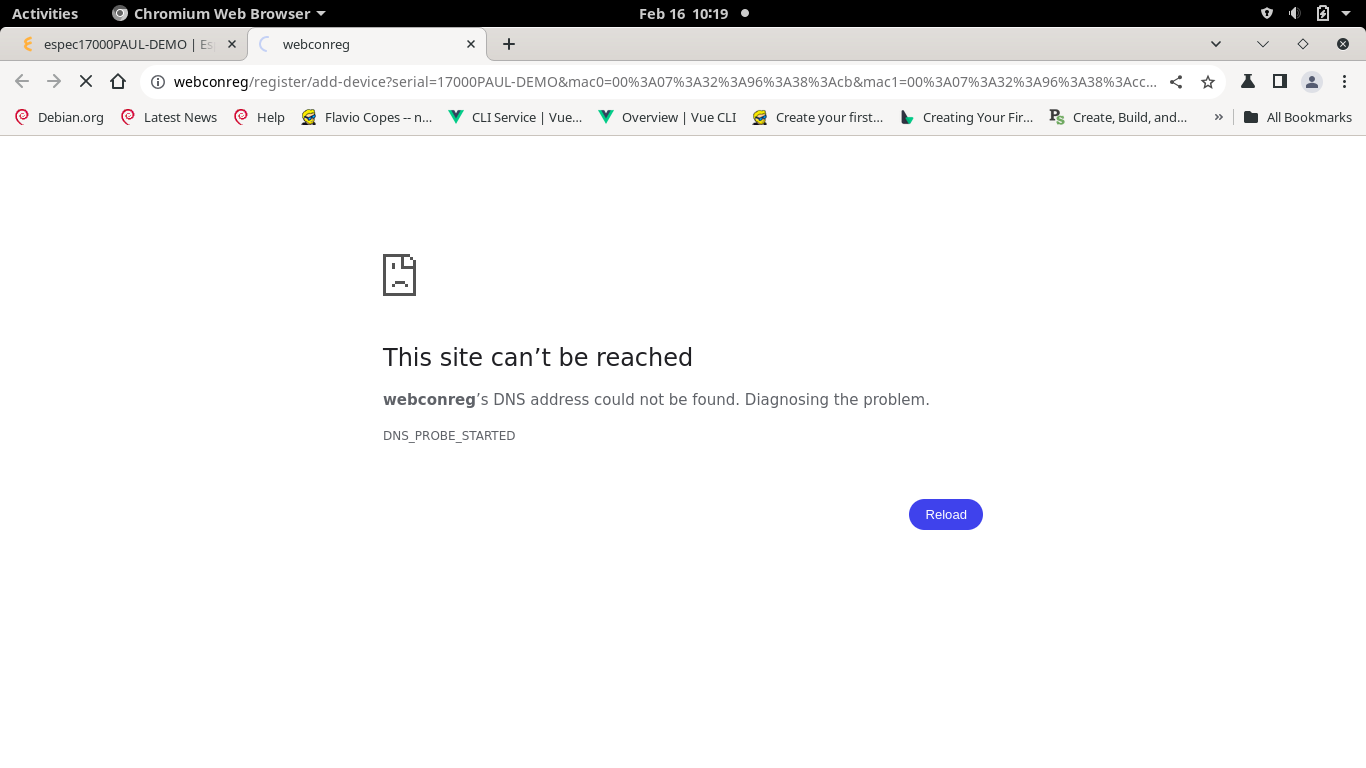
At this point, EWC tries to access our registration server (opened in the second tab, see Figure below) to register itself, but it fails because this is a static private network setup. This is the last step in this Phase 1.
-
Power down the Web Controller and chamber, then proceed to Phase 2 (below).

-
Reconnect your EWC to join the main network.
-
Make sure your PC is also connected to the main network.
-
Cycle power to all the devices.
-
After 1 or 2 minutes, open a Web browser on your PC and navigate to:
where SN is the serial number of the chamber (Phase 1, step 7). You may also use the Web Controller Locator Utility in Section 3.2 to locate your EWC via its hostname this time.
-
When the Setup Wizard page appears, log in using the admin account.
-
Click ACCEPT in the Terms of Service page to continue.
-
When the Device Registration and Verification window reappears, proceed to Section 4.4.3 to re-enter the chamber serial number (see Figure) to register your Web Controller and follow the steps outlined therein to complete the configuration and registration.
To ensure proper registration of the Web Controller, production must perform the Setup Wizard on all Web Controllers, including service orders, prior to shipment. This Setup Wizard includes a step to register the Web Controller using the chamber serial number. This registration number is kept and tracked by our Web Controller database system.
Login with the following credentials.
-
User Name: “admin”
-
Password: “admin”

IMPORTANT: Production must close out the Setup Wizard (with the X button) at the Email settings page. These three options (Email, User and Network settings) must be left for customers to complete. This means production must end the Setup Wizard on the third page after completing the chamber configuration and Web Controller registration (described below).
Click Accept to accept terms of service. This is different from the previous Web Controller versions where “Terms of Service” is always present until the Setup Wizard is completed by the customer.

Configure your EWC based on the applicable work order:
-
Factory Install: For factory setup, configure your EWC for the target chamber based on the job description using options from chamber category, model selection and controller, communication interface and options (see Figure below), and click ACCEPT. EWC immediately applies the configuration and restarts itself (registration window may flash momentarily). A new Setup Wizard reappears. Click ACCEPT again and proceed to Section 4.4.
-
Service Replacements: For service replacements, configure your EWC based on the chamber type or information in the service job; a chamber controller prototype is required in order to complete the registration; see Paul Nong-Laolam in the software engineering team for assistance.
-
U-Web Kit: For U-WEB-KIT setup, follow the same procedure outlined for service replacements.

Registration of EWC must be completed before EWC leaves the factory.
The Device Registration and Verification pop-up window (in the Figure below) indicates that chamber configuration is complete but it has not yet been registered (with serial number not yet entered). All four check marks must be completed.

-
If you have only the last check mark to complete (as depicted in Figure above), proceed to Section 4.4.3 to complete the registration.
-
If you have several incomplete check marks, proceed to Section 4.4.2 to resolve them, then proceed to Section 4.4.3.
The following figure shows various Device Verification issues and their description.

-
Data logging storage drive: If this does not have a green checkmark the possible causes are:
-
The mSATA drive is not installed correctly.
-
Steps 7 through 11 of the Flashing Firmware to the Hardware may not be performed correctly, or the SSD device may be faulty.
-
-
Chamber configuration: If this does not have a green checkmark the possible causes are:
-
The Web Controller is intentionally being shipped without a chamber configuration, in this case press the check mark on this list entry.
-
The skip button was accidentally pressed on the previous screen.
-
Close this screen with the X button on the top right.
-
Press the BACK button on the setup wizard.
-
Configure the chamber and press ACCEPT.
-
-
The web controller is having trouble connecting to the chamber:
-
You may press the refresh button on this line to retry the test as the errors may be related to startup delays.
-
Ensure the correct configuration is setup on the previous screen.
-
There is a communication problem between the web controller and chamber, that must be diagnosed to resolve this issue.
-
-
-
Chamber Controller Model/Setup: The purpose of this checkmark is to ensure the target chamber has been configured correctly with all the required features (or options) selected. The possible causes of the red X are:
-
Chamber configuration met the minimum requirement for this chamber when item 2 (above) has a green checkmark. Refer to the work order sheet for information about all the required features on the target chamber. For example, the chamber has a PTCON but it has not been selected.
-
If the red X also appears on item 2 (above), the target chamber is incorrectly configured. Refer to the work order sheet for information about all the required features on the target chamber.
-
For F4T: If a green checkmark is on but item 2 (above) has a red X (indicating chamber configuration error), as illustrated in the following figure, there is a possibility that the Web Controller is expecting a limit card on F4T (the error message will indicate a reading error). Contact Paul or Myles for assistance.
-
-
Chamber registration: If this does not have a green checkmark the possible causes are:
-
The device has not been registered yet, perform that and this will resolve.
-
The web controller is not connected to the ESPEC network and the registration must be performed manually. In this case ensure the setup was completed via scanning the QR code and press the check mark on this row to validate it.
-

This section continues from Section 4.4.1 or Section 3.3.2 (Phase 2, Step 7) to complete the EWC registration.
-
Serial Number and Customer (Optional): Click the Serial Number field (shown by the arrow) and enter the chamber serial number. Click the Customer field (if required) and enter customer's name, and click REGISTER.
-
EWC accesses our registration server (opened in a new tab, see Figure below) to register itself. Click Submit to complete the registration. Note: The database server will give a warning and rejects the registration if it found a duplicate on serial number.
-
Click the EWC tab as shown by the arrow (see Figure) or close out the Web Controller Utilities tab.
-
Click the check mark of Chamber Registration (indicated by the arrow) and click ACCEPT (indicated by the arrow).
-
EWC and chamber registration is complete.
-
IMPORTANT: Every time you restart EWC and after logging in, click ACCEPT in the Setup Wizard. Then click X (indicated by the arrow) to close out the Setup Wizard page when you get to the Email Settings page. Note: Email, User and Network Settings pages are for the customer to complete.


Procedure used for flashing the web controller with a bootable USB drive, this requires a HDMI touch screen or HDMI monitor and mouse.
-
Connect the touch screen to the web controller assembly via the HDMI and USB cables.
-
Plug in the firmware USB drive.
-
Apply power (or cycle power) to the web controller.
-
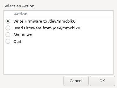
Once the system fully boots you will be presented with the following menu:
-
Select the “Write Firmware to /dev/mmcblk0 option and press OK.
-
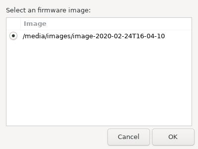
Now select the newest firmware (It will be pre-selected), and press OK.
-
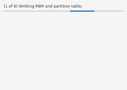
The firmware will now be installed to the system.
-
Once the firmware is installed, select yes to shut down the system.
-
Remove the firmware USB drive.

Setup procedure for the BIOS on the web controller when not using an automatic setup USB dongle. This procedure requires a HDMI monitor and USB keyboard.
-
Ensure a keyboard is plugged into the web controller in addition to the monitor.
-
Cycle power to the web controller.
-
Quickly tap the DEL key repeatedly until a password prompt appears.
-
Press the ENTER key (no password is needed).
-
Set the mPCIe slot on the device to be used in mSATA mode:
-
Select the “Chipset” tab by pressing the left/right arrow keys.
-
Select “Mini PCIe / mSATA Swi” by pressing the up/down arrow keys.
-
Press Enter
-
Select “mSATA”
-
Press the ENTER key.
-
-
Configure the 1st boot device to the internal “Hard disk”, instead of USB:
-
Select the “Boot” tab by pressing the left/right arrow keys.
-
Select the “Boot option # 1” by pressing the up/down arrow keys.
-
Press the ENTER key.
-
Select “Hard Disk:debian”
-
Press the ENTER key.
-
-
Save the settings and quit the BIOS Setup:
-
Press F4 key.
-
Select “Yes” by pressing the left/right arrow keys.
-
In order for the PC to communicate with EWC, it must also use a Class C static network protocol configured as follows:
     IP Address:           192.168.0.84  (recommended IP)
     Subnet Mask:          255.255.255.0
     Gateway:              192.168.0.1
     Preferred DNS server: 8.8.8.8
     Alternate DNS server: 8.8.4.4
Complete the following steps on MS Windows 8/10/11:
-
Hold down the Windows key and press R to launch the Run Command dialog box.
-
Enter ncpa.cpl into the Open box field and press Enter or click .
-
Point and Right-Click the “Local Area Connection” icon, then click Properties from the drop-down menu (see the following figure). Verify that the correct Ethernet port is selected, if your PC has multiple ports.
-
In the “Local Area Connection Properties” window, confirm or place the check mark in front of “Internet Protocol Version 4 (TCP/IPv4)”(see Figure below).
-
Click to highlight “Internet Protocol Version 4 (TCP/IPv4)” and then click Properties in the lower-right corner.
-
In the “Internet Protocol Version (TCP/IPv4) Properties” window, turn on the radio button for “Use the following IP address:” and enter these settings (see Figure below for detail):
IP Address: 192.168.0.84 Subnet Mask: 255.255.255.0 Gateway: 192.168.0.1 -
In the “Use the following DNS server addresses:” section, enter the following settings (see Figure below):
Preferred DNS server: 8.8.8.8 Alternate DNS server: 8.8.4.4 -
Turn on “Validate settings upon exit” with a check mark and click OK.
-
Click OK to close “Local Area Connection Properties” window.
-
Close out the Network Connections window.
-
Return to Section 3.3 and Open a Web browser and navigate to: http://192.168.0.83/ to access EWC.


