EWCv3.3 T‐series Upgrade Procedure
[TOC]
This document provides a step-by-step procedure to upgrade your T-series chamber with our ESPEC Web Controller Upgrade kit (or EWC kit). The EWC kit is based on ESPEC Web Controller (EWC), Version 3, capable of communicating with the integrated programmable logic controller (PLC) that directly controls the chamber. The EWC kit therefore provides control and instrumentation of your T-series chamber in place of the Typhoon Manager (TM) software. It can operate as a standalone system for security and isolation or it can operate as a networked system to provide a secure and remote access for chamber operation.
The EWC kit consists of the embedded computer in a black box, a DC power adapter, and an Ethernet cable, as depicted in the following figure. In the upgrade process, the EWC kit will be integrated with the T-series and control PC system. The control PC will be used to access EWC via a Web browser to control and operate the chamber.

The EWC operation manual is available online: https://github.com/EspecNorthAmerica/ESPECWebController/wiki/EWCv3.3-Manual-for-T%E2%80%90series. It is also available as an embedded PDF manual in the EWC software itself, found under the About menu.
The upgrade procedure involves two separate stages: (1) hardware integration and (2) software configuration. The first stage involves integrating the EWC kit as part of the T-series chamber system (Section 1.1) and setting a static network on the control PC (Section 1.2). The second stage involves completing the Setup Wizard in the EWC software (Section 3).

This section outlines a step-by-step instruction to connect the EWC kit to your existing T-series chamber and control PC, as depicted in the foregoing figure.
-
Exit and close the TM session on the control PC.
-
Turn off the chamber. Note: It is not necessary to turn off the chamber since Ethernet connection is hot pluggable. However, turning off the chamber is the safety protocol. Refer to the chamber operation manual for detail.
-
Unplug the PLC Ethernet cable from the control PC (labeled as TM/PLC) in the following figure, and plug it into ETH-1 on the EWC black box (see Figure below).
-
Verify that T-series chamber and EWC are connected using this Ethernet cable via their ETH-1 ports, as depicted in the following figure.
-
Connect EWC and control PC via their ETH-0 ports, as depicted the following figure, using the Ethernet cable supplied with the EWC kit.
-
Apply power to the chamber (optional if step 2 was skipped).
-
Plug the barrel jack from the DC power adapter (supplied with the EWC kit) into the EWC black box labeled Power (see Figure above) to boot EWC. Boot process will complete within 2-3 minutes.
-
Proceed to Section 1.2 (below) to complete the static IP configuration on the control PC.

When EWC detects a network signal on its ETH-0 port, it first applies DHCP protocol to obtain an IP address from the DHCP server to join that network. If that fails–no DHCP service available, EWC uses its preconfigured Class C static network configurations:
     IP Address: 192.168.0.83
     Subnet Mask: 255.255.255.0
     Gateway: 192.168.0.1
This static network protocol occurs when EWC is connected directly to the control PC (or a static network). Modern devices can connect directly to each other with a standard CAT 5/6 cable without the need for a cross-over cable.
In order for the control PC to communicate with EWC, it must also use a Class C static network protocol configured as follows:
     IP Address: 192.168.0.84    (recommended IP)
     Subnet Mask: 255.255.255.0
     Gateway: 192.168.0.1
     Preferred DNS server: 8.8.8.8
     Alternate DNS server: 8.8.4.4
Complete the following steps on the control PC:
-
Hold down the key (the key between and ) and press to launch the Run Command dialog box.
-
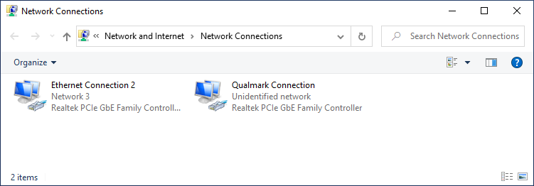
In the Run dialog box, enter ncpa.cpl into the Open box field and press . Two network devices are listed in the Network Connection window, as depicted in the following figure.
-
Point and right-click the “Ethernet Connection 2” icon, then click Properties from the drop-down menu (see the following figure). Note: The second network device “Qualmark Connection” is the network device used for communicating with the T-series chamber/PLC (see Figure below). It is to be left alone.
-
In the “Ethernet Connection 2 Properties” window, confirm that there is a check mark placed in front of “Internet Protocol Version 4 (TCP/IPv4)”, as depicted in following figure. If not, check it. Click to highlight “Internet Protocol Version 4 (TCP/IPv4)” and then click Properties in the lower-right corner.
-
In the “Internet Protocol Version (TCP/IPv4) Properties” window, turn on the radio button for “Use the following IP address:” (Figure below) and enter these settings (see Figure below):
IP Address: 192.168.0.84 Subnet Mask: 255.255.255.0 Gateway: 192.168.0.1 -
In the “Use the following DNS server addresses:” section, apply the following DNS values (see Figure below):
Preferred DNS server: 8.8.8.8 Alternate DNS server: 8.8.4.4 -
Turn on the “Validate settings upon exit” with a check mark and click OK (refer to the following figure).
-
Click OK to close “Ethernet Connection 2 Properties” window.
-
Close out the Network Connections window.
-
Open a Web browser and navigate to http://192.168.0.83/ to access EWC.
-
The user interface of EWC appears in the Web browser, as depicted in the figure below.
-
Proceed to Section 3 to complete the initial setup of EWC.


This section outlines a step-by-step instruction to connect the EWC kit to your existing T-series chamber and control PC, as depicted in the following figure.

The upgrade procedure involves two separate stages: (1) integrating the EWC kit as part of the chamber system, as depicted in the following figure, (2) software configuration. The setup in the first stage requires an additional Ethernet port for EWC to join the main network using a DHCP protocol but static configuration also is possible. The control PC is presumed to be using the same protocol. The second stage involves completing the Setup Wizard in the EWC software (Section 3).

This section provides a step-by-step instruction to connect the EWC kit to your existing T-series chamber and control PC, as depicted in the foregoing figure, starting with the first one.
-
Exit and close the TM session on the control PC.
-
Turn off the chamber. Note: It is not necessary to turn off the chamber since Ethernet connection is hot pluggable. However, turning off the chamber is the safety protocol. Refer to the chamber operation manual for detail.
-
Unplug the PLC Ethernet cable from the control PC (labeled as TM/PLC) in the following figure, and plug it into ETH-1 on the EWC black box.
-
Verify that T-series chamber and EWC are connected using this Ethernet cable via their ETH-1 ports, as depicted in the following two figures.
-
Using the Ethernet cable supplied with the EWC kit, connect EWC to the main network using the ETH-0 port, as depicted the foregoing figure and the following figure.
-
Verify that control PC is connected to the main network using its ETH-A port as depicted in as depicted the foregoing figure and the following figure.
-
Apply power to the chamber (optional if step 2 was skipped).
-
Plug the barrel jack from the DC power adapter (supplied with the EWC kit) into the EWC black box labeled Power (see Figure [ewc-main-network-connect-001]) to boot EWC. Boot process will complete within 2-3 minutes.
-
Launch a Web browser on the control PC (or any PC on the network) and navigate to http://especSN#.local/ to access EWC, where SN# is the chamber serial number (see the following figure).
Example: http://espec40T12211665.local/
-
The user interface of EWC appears in the Web browser, as depicted in the following figure.
-
Proceed to Section 3 to complete the Setup Wizard of EWC.


When EWC is powered on for the first time, it presents a Setup Wizard for post installation that includes e-mail alert and/or password recovery, password reset and network settings.
The following steps continue from Step 12 of Section 1.2 or Step 11 of 2.1.
IMPORTANT NOTE: If you click SKIP on any of the following Setup Wizard pages, they will reappear every time you restart and log into EWC.
At the login screen depicted in Figure [ewc-login-001], enter username and password:
   username: admin
   password: admin
and click to log in.
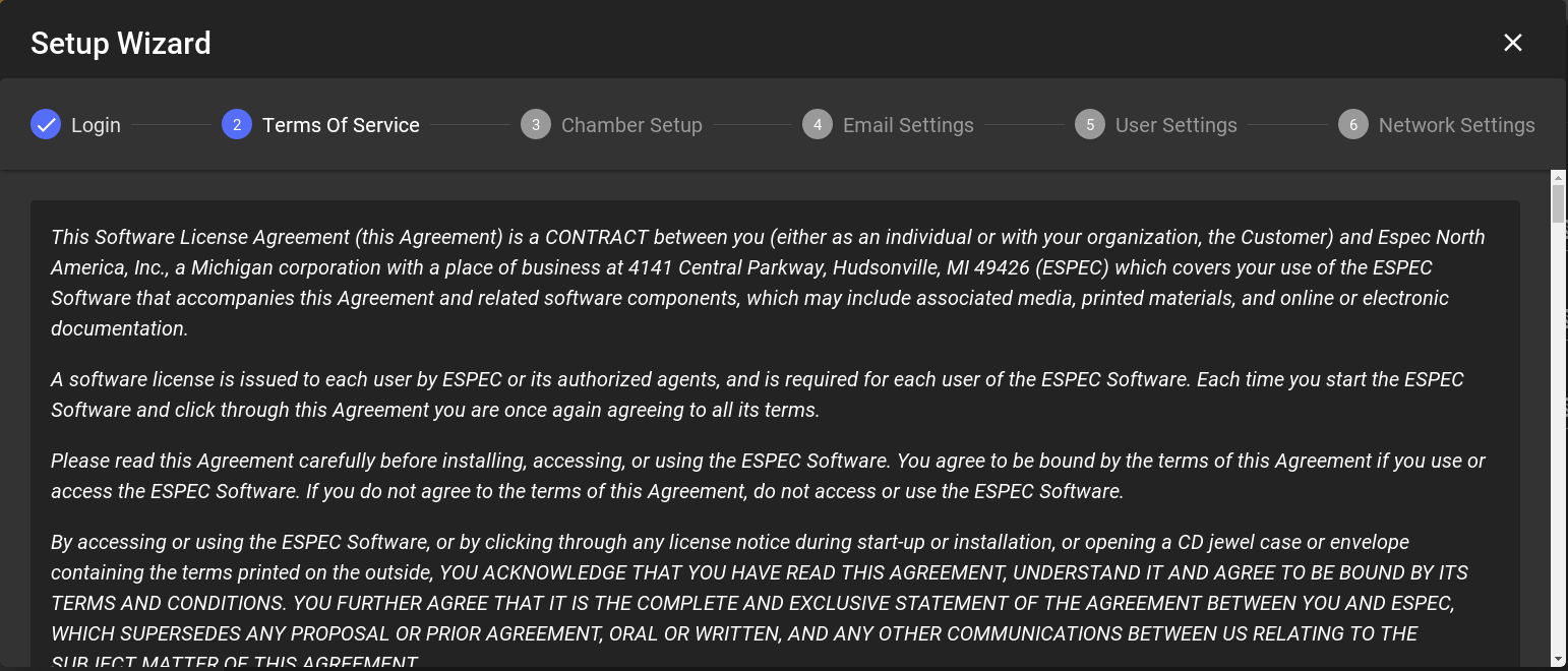
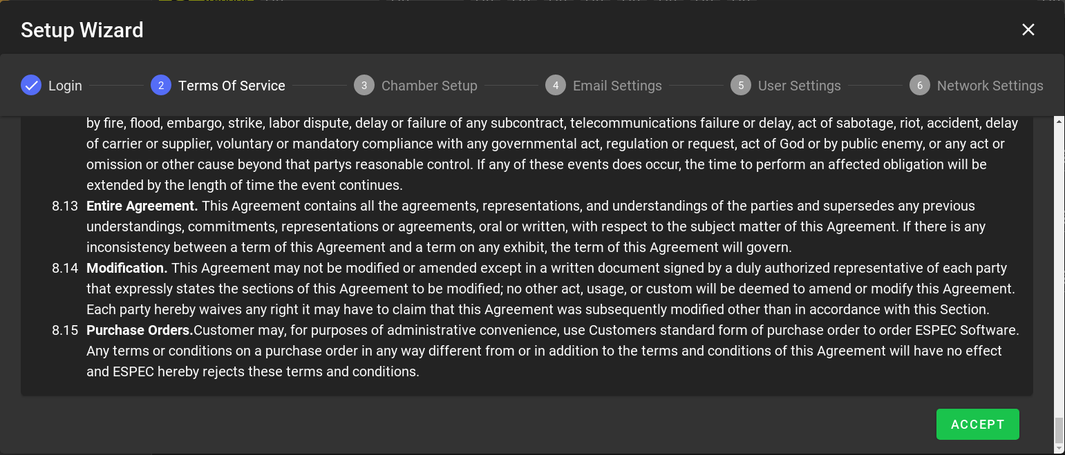
Apply the scroll bar to read through the Terms of Service, then click to accept the terms (see the two following figures).
Chamber configuration status may display communication error in the Email settings page as depicted in the following figure. If this is the case, click the BACK button to return to the Chamber Setup page (see the following two figures) to confirm or reconnect the chamber with the correct configuration for model, type and features (consult the chamber operation manual for that information). If the Email settings page displays chamber status as depicted in the figure in the next section, proceed to the next section (Email Settings).

Refer to the following figure to connect the chamber with the following steps:
-
Confirm or select T-Series Chamber.
-
Select Model/Type (e.g., T2.5, T4.0) from the spin button. Refer to your chamber operation manual for this information. Check the Vibration box if applicable.
-
Under the Optional Features column, check any box that applies to your chamber.
-
Click to apply the settings.

Once chamber connection has been established, the Setup Wizard returns (i.e., forwards) to the Email Setting page as depicted in the following figure.
For a standalone system (Section 1), this setup page can be left with its default setting. Click ACCEPT in the following figure to continue.
For a networked system (Section 2), and if this system has access to the Internet, account recovery e-mail and alert e-mail can be configured at this time. However, these settings can be configured later using the Settings menu. This setup page can be left with its default setting. Click ACCEPT in the following figure to continue.

It is imperative that the admin password be changed to something secure to protect both your chamber and EWC. The following figure presents a first chance to reset the admin password.
-
Enter current password: admin
-
Enter new password twice.
-
Click .

NOTE: An error message, as depicted in the following figure, will be displayed if the admin password has not been reset. You can still use the factory password but you will put your system at high risks of security breach. This admin password can be reset later via the Settings menu.

The Network Settings page displays hostname and network protocol (DHCP or static) and fallback static IP settings assigned to the ETH-0 port of EWC (called eth0), as depicted in the following figure.

The DHCP box is checked by default such that EWC is ready to use DHCP when it detects one. The IP address leased by a DHCP server to EWC can be found under the Network Settings submenu (under the Settings menu). For a standalone system, this DHCP box is also checked when EWC uses its fallback static IP settings.
-
Click ACCEPT to continue.
-
The Setup Wizard is complete.
-
EWC now displays its home page in Overview mode and is ready for chamber operation.
-
Single-User or Multi-User:
-
If multiple operators need to control and operate the chamber, they each should have a separate account on the system. Consult our ESPEC Web Controller User’s Manual at https://github.com/EspecNorthAmerica/ESPECWebController/wiki/EWCv3.3-Manual-for-T%E2%80%90series for detail on how to create different accounts and privileges for these operators.
Users may begin to log into EWC to operate the chamber as soon as their account has been created.
-
If this is a single-user system, EWC is now ready for operation. Refer to our User’s Manual in the above URL link for detail. The embedded online User’s Manual is also available under the About menu.
-
A static IP address can be set on EWC. If a different static network configuration is needed, log into EWC using the admin account and configure the desired static network under the Settings menu via the Network Settings submenu shown in the following figure.

Complete the following steps:
-
Log in as admin.
-
Click Settings (in the menu bar).
-
Click Network Settings (in the submenu bar).
-
Uncheck the DHCP box.
-
Edit the IP address field (replacing 192.168.0.83 with a new value).
-
Enter the appropriate values for Net Mask, Gateway, DNS1 and DNS2.
-
Click Save in upper-right corner.
-
Open a new Web browser and navigate to EWC with the new IP address.
Warning! To revert EWC to use DHCP protocol and its preconfigured static network setting, you must check the DHCP box and also enter 192.168.0.83 in the IP address field before you reboot and connect EWC back to a DHCP or Class C static network. If you failed to apply these settings, EWC will still be using the custom static IP address as its fallback static network protocol.
The Operation Manual for ESPEC Web Controller is available in two formats, embedded PDF and online wiki.
-
Embedded PDF: The embedded PDF is accessible from the MANUAL tab under the About menu, as depicted in Figure [embedded-manual]. To view the PDF manual, access the buttons according to the numbered labels in the figure.
-
Online Wiki: The EWC User Manual for the T-series can be viewed online here:
https://github.com/EspecNorthAmerica/ESPECWebController/wiki/EWCv3.3-Manual-for-T%E2%80%90series
