3 ‐ Code Breakdown
This section is useful for anyone who is delving into our code for specific information or who is interested in learning how our project works and the usage of each Verilog component/module. The module overview section is also useful for you to briefly view the usefulness of each file for your project. If you are looking for specific Verilog tutorials, see the pages tab on the right and click on the one that you need.
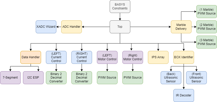
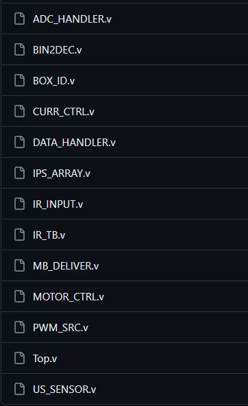
In our repository under main/Nautilus Code/Nautilus_L1.srcs/sources_1/new you will find the sources for our Nautilus platform. These sources make up Nautilus's key components of the HDL design. One key difference between Verilog and other languages is that it isn't considered "code" but instead an HDL (Hardware Description Language) design. You are describing logic devices and how they interact with each other. The Basys 3, which is an FPGA and not a microcontroller, does not have a processor on it or any traditional firmware like a microcontroller. It can be configured to run any digital logic circuit that you design for it. The Basys board runs an implementation of your design which allows it to complete many parallel processes synchronously and asynchronously (in sync with a clock or as fast as the circuit can update its registers).
Vivado, which is described in another section, is the Verilog software suite that allows us to write the HDL and generate a design for the Basys 3. For the sake of these tutorials, I will refer to the Verilog as "HDL" and "code" (because semantics are dumb).
In Verilog, each module created in a .v file will be invokable in the other files. When you view the sources for this project, each .v file contains one or several modules within it. We tried to contain redundant modules inside the file of its parent module. For example, the "IR Input" module is written in a file that also contains the "Morse Decoder" module that it needs to decode its signal. See below:
//The parent module
module IR_INPUT
#(parameter CLOCK_TO_MS = 100000)(

input enable,
input clk,
input IR_Pin,
output LED,
output reg[59:0] process_stream,
output reg overflow,
output wire dot_match,
output wire dash_match,
output morse_fallback,
output [3:0] value,
output morse_ready
);
...
endmodule

//A secondary module utilized by the parent
module MORSE_DECODER (input enable, input clk, input[59:0] bitstream,
                      output reg ready, output reg fallback, output reg dot_match, output reg dash_match,
                      output reg [3:0] out);
...
endmodule
If you need a good source for reading how modules work in Verilog, here is one. For this project, the modules and their files are all found in the Nautilus_L1.srcs folder, and you can reference the diagram above to see the hierarchy displaying which modules contain implementations of others.
Here are the modules in order of precedence and their function. We will cover the full breakdown of these modules in the next section.
-
Top Module - TOP
- The bridge between the I/O of the Basys 3 and the software. This module contains all of the other modules within the system and interconnects them through wires, registers, and inputs/outputs with the Basys 3 constraints file (the file specifying how the physical ports connect to our HDL designators)
-
Motor Control - MOTOR_CTRL
- Processes motor control logic via PWM by implementing a PWM Source and a 7-bit decimal mode specifying percent speed (7'd0=0% speed, 7'd100=100% speed). This module also uses the L298 H-Bridge "braking" feature to stop the tracks more efficiently when mode is set to 0. This module can be interrupted by a Current Control module when overcurrent is detected.
-
PWM Source - PWM_SRC
- A simple implementation of PWM contained within one module. Defaults to 100 Hz operating frequency. Separate implementations of this module can operate at different frequencies and the module can be used in 7 bit or 4 bit mode. The 7 bit mode directly correlates the input mode to frequency like specified above in the motor controller.
-
Current Control - CURR_CTRL
- Converts raw ADC data into amp data based off a known shunt resistor value of 1 Ohm. This module samples the ADC data and overflows if a high current over 1 A exists for a measurable amount of time. Two of these modules exist, one for each motor. If overflow is detected, then an interrupt signal is outputted to disable the motor controller.
-
ADC Handler - ADC_HANDLER
- Handles input/output signals from the ADC wizard. The wizard sequences multiple pins on the Basys board and reads the analog-digital-conversion of signal from those pins. This module splits that data into the multiple channels as output wires. Other modules, such as the Current Control module, interprets the ADC data. In the section for setting up the ADC Wizard***, you will find more useful information for this module.
-
Data Handler - DATA_HANDLER
- This module contains the code required to display debug information from the Nautilus system. All debug registers from other modules feed the Data Handler so that different aspects of the system can be debugged externally. It displays data on the Basys 7-Segment display and passes data from other modules into a 20-byte register that is sent to an ESP8266 over I2C. That ESP8266 communicates the data over WiFi and to an LCD screen. The 7-Segment display code is easy to understand, and the I2C should only be implemented by more advanced Verilog users.
-
IPS Array - IPS_ARRAY
- This module handles the IPS sensor inputs for the purpose of metallic tape detection and subsequent track navigation. The algorithm for track navigation is full-proof to handle any angle of tape and can even navigate crossing paths while maintaining direction. This module switches between 4 states: FORWARD, REVERSE, ROTATE, and FORWARD_SPECIAL in a complex state machine to determine track direction and prevent the rover from exiting. See the navigation flow chart*** for more information.
-
Box Identifier (PDU) - BOX_ID
- Monitors the ultrasonic sensors and interrupts the drive state of the robot to scan an infrared signal emitted by an IR emitter. This module manages all the timings for scanning, dispensing, and determining how long to wait before detecting another box.
-
Ultrasonic Sensor - US_SENSOR
- This module is designed to interface with an ultrasonic sensor to measure distances and provide filtered detection outputs. It generates trigger signals, measures the time taken for the echo to return, and detects objects based on distance calculations and filtering.
-
IR Decoder - IR_INPUT
- The provided Verilog code consists of two modules, IR_INPUT and MORSE_DECODER, which together work to decode an infrared (IR) Morse code signal. The IR_INPUT module processes IR Morse code pulses and generates a bit stream, while the MORSE_DECODER module takes this bit stream and decodes it into Morse code characters.
-
Marble Delivery - MB_DELIVER
- The Verilog code defines a module named MB_DELIVER, which operates 3 servo gates based on a 3-bit input signal and generates PWM outputs for controlling the servo positions. This module fulfills the marble delivery portion of the project and is activated by the PDU module.
-
I2C Communications - I2C_COMMS
- The I2C_COMMS module facilitates I2C communication by sending and receiving 20 bytes of data through the SDA and SCL lines. It handles start and stop conditions, address and data reception, ACK generation, and data transmission. This module allows the exchange of data between the module and an ESP device using the I2C protocol, following the defined communication cycle and addressing scheme.
Darkon Design, a small company founded by members of this repository, offers 3D printing to the Lubbock and TTU community. Check out our website, darkon.design, for competitive prices on 3D printing services and for other products. We offer high quality prints and will print for prices cheaper than you can find on Texas Tech campus! TTU Students and ECE Project Lab students are eligible for a substantial discount. We are also looking to expand our small community of 3D Printer owners to better serve the Lubbock community! Reach out to us on our website for any inquiries that you may have.