Repository navigation
Working Principle
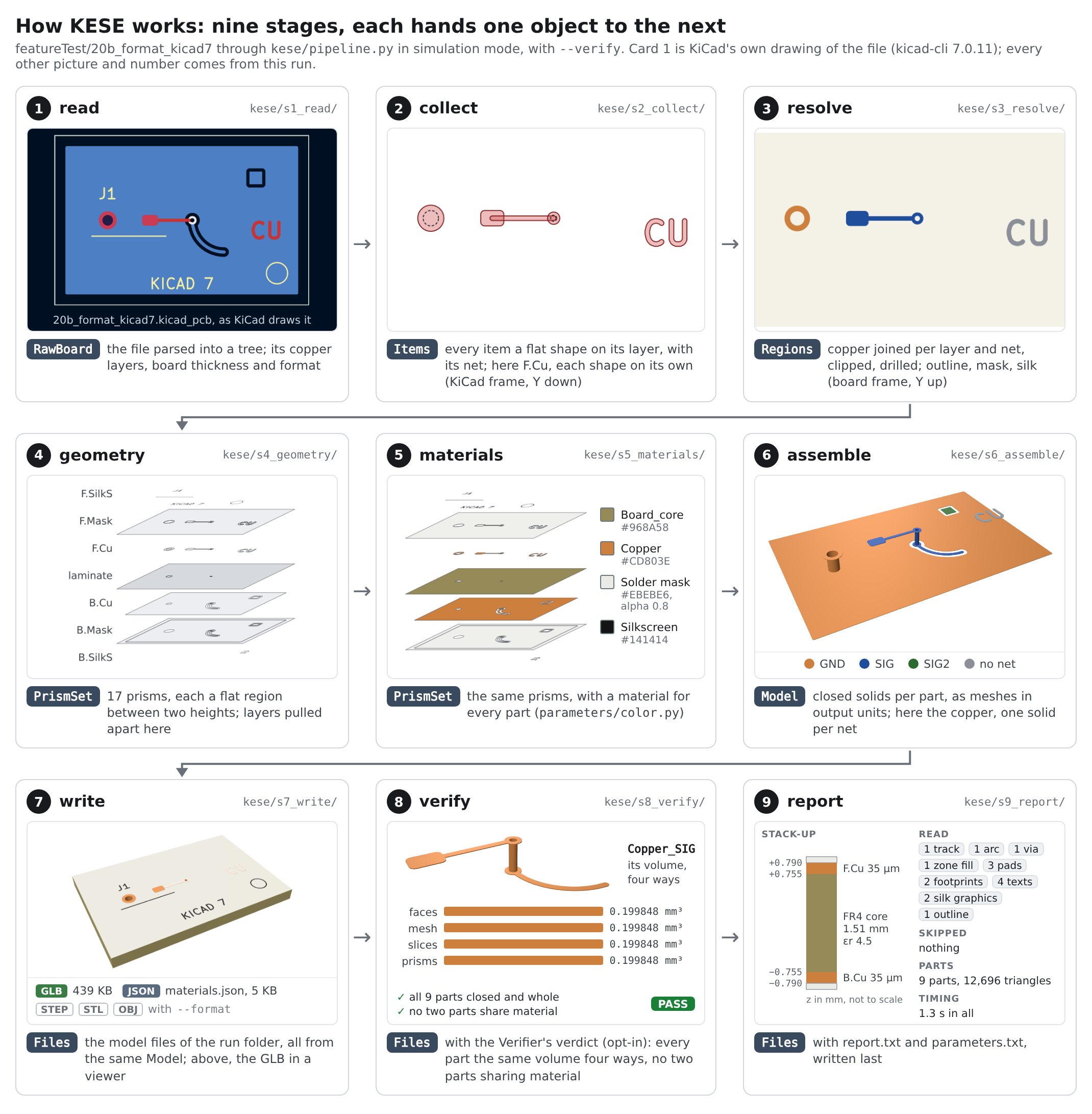
KESE is one straight pipeline, kese/pipeline.py. Every stage is a folder in kese/ with a
run(what the stage before made, job) that returns what it makes:
STAGES = (read, collect, resolve, geometry, materials, assemble, write, verify, report)

out = pcb_path
for stage in STAGES:
out = stage.run(out, job)| # | Stage | Gets | Gives | What it does |
|---|---|---|---|---|
| 1 | s1_read |
.kicad_pcb file |
RawBoard |
Parses the file and lists the copper layers, the board thickness and the file format; every rule that depends on the KiCad version is in parse_kicad_version.py. Warns outside KiCad 4 to 10 and above eight copper layers; stops if F.Cu or B.Cu is missing |
| 2 | s2_collect |
RawBoard |
Items |
Every track, pad, zone fill, graphic, text and via as a flat shape on its layer, with its net, in KiCad's frame; the stack-up from Board Setup; counts of what was read and what was skipped |
| 3 | s3_resolve |
Items |
Regions |
The outline; the copper joined per layer and net, clipped and drilled; barrels, edge plating, mask openings and silkscreen; everything moved to the board frame and snapped to the grid |
| 4 | s4_geometry |
Regions |
PrismSet |
The heights from the stack-up, once; every part as prisms, each a flat region between two heights |
| 5 | s5_materials |
PrismSet |
PrismSet |
A material for every part (Colorizing) |
| 6 | s6_assemble |
PrismSet |
Model |
Closed solids (simulation mode) or the visible surface (visual mode), in the output units and orientation (6.2) |
| 7 | s7_write |
Model |
Files |
GLB, STEP, STL, OBJ and materials.json in a new run folder |
| 8 | s8_verify |
Files |
Files |
Only with --verify: every part closed and consistently wound, its volume the same four ways, no two parts overlapping (Checks, Errors And Warnings) |
| 9 | s9_report |
Files |
Files |
report.txt and parameters.txt
|
Nothing is rebuilt per output format: stage 7 writes every file from the one Model. The files are
written before the Verifier runs, because it also checks the written GLB, and the report comes last
so that it carries the Verifier's result.
Two shared folders sit below the stages: kese/core/ holds the tools that know nothing about
stages (the s-expression parser, 2D shapes, the boundary of a stack of prisms, triangulation, the
stroke font), and kese/model/ the classes handed from one stage to the next. A stage uses only
those, parameters/ and the stages before it; tests/test_layout.py checks this
(Project Output Organization shows the whole tree).
Everything is built from 2D regions snapped to one grid, between heights worked out once from the stack-up:
# kese/core/shapes2d.py, snap(): every polygon that is not on the grid yet is rounded to it
off = ~on_grid(parts)
parts[off] = shapely.set_precision(parts[off], grid()) # Geometry.SNAP_GRID_MM, 0.1 µm- Every vertex of every region lies on the grid; heights are not rounded. So two parts that touch have the very same edges and heights: no gap and no overlap between them, and every part's surface closes. The Verifier's overlap test finds no shared material on any board of the regression suite.
- Where a region would pinch to a point (two pieces touching at one vertex), a disc of
Geometry.PINCH_POINT_OPENING_MMis cut out of the smaller piece so that the solid can close (kese/core/pinches.py). Those vertices sit just off the grid. - One known exception, where parts can overlap or leave a gap: the wedge beside a sloped copper
wall (
Copper.ETCH_FACTOR > 0, see Copper And Traces). - The price: curves are polygons, in the meshes and in the STEP file alike.
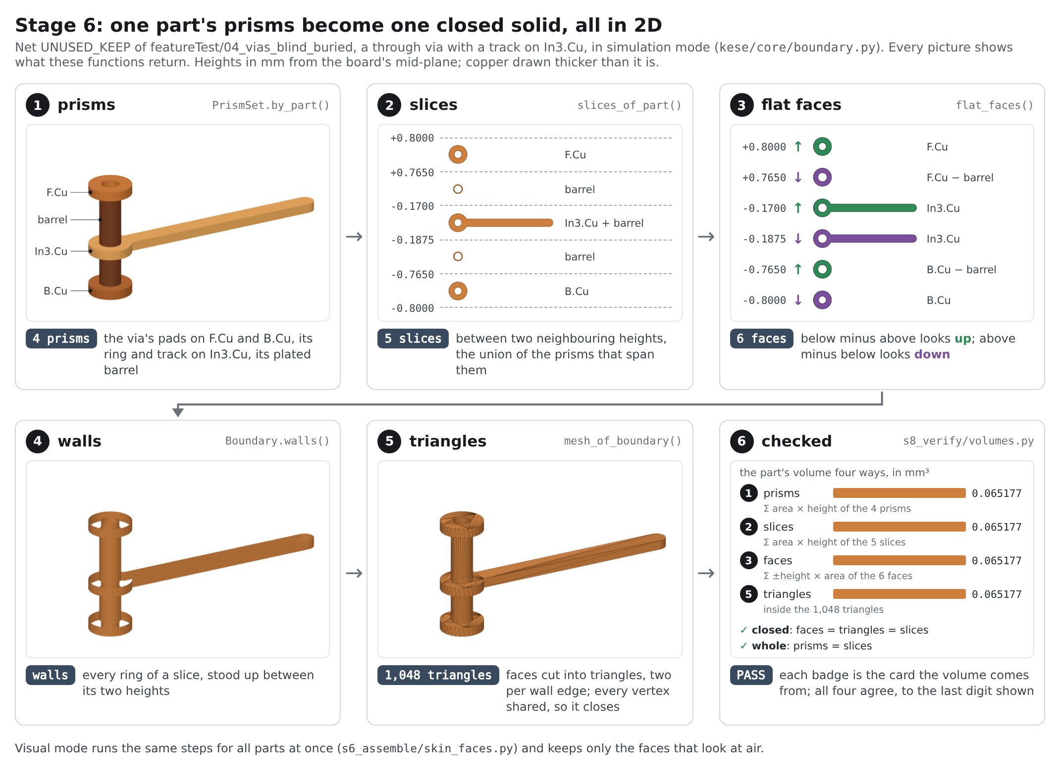
Stage 6 needs no CAD kernel. Every part's surface is worked out in 2D from its prisms
(kese/core/boundary.py) and then cut into triangles (kese/core/boundary_mesh.py):
def boundary_of(part, prisms, log=None):
    """The prisms of one part -> its Boundary, closed by construction."""
    levels = heights_of(prisms)                    # every height where a prism starts or ends
    slices = slices_of_part(prisms, levels, log)   # the material between two neighbouring heights
    for _ in range(ROUNDS):
        flats = flat_faces(slices, levels)         # below minus above looks up, above minus below down
        slices, changed = slices_sharing_vertices(slices, flats, levels, log)
        if not changed:
            break
    ...

mesh = mesh_of_boundary(boundary) # faces cut into triangles, two per wall edge- The walls are the rings of every slice, stood up between the slice's two heights
(
Boundary.walls()). Faces and walls must meet on identical edges, so the slices that meet at a height are given each other's vertices, and their faces' vertices, until nothing changes (kese/core/vertices.py). Then the mesh closes by construction. - The faces are cut by earcut, as in KiCad's 3D viewer; a polygon of more than
Geometry.TRIANGULATE_CELL_POINTSpoints strip by strip, as KiCad cuts big polygons into cells. A cut that does not close exactly on the polygon's edges is done again by GEOS's constrained Delaunay triangulation, throughshapely(kese/core/triangulate.py). Earcut makes a flat triangle (three points on one line, area zero) where a ring has a point on a straight run, the vertex another face shares; such a triangle is flipped away with its neighbour across its long edge, so no mesh holds a triangle of zero area, which some meshers and STL importers reject. -
Run.WORKERSparts are built at once, the biggest first. Every part keeps its faces (itsBoundary), and the STEP writer writes those same faces as a closed solid. - Visual mode does the same for all parts at once and keeps only the faces between material and
air (
skin_faces.py,skin_mesh.py, see Output Modes). - Last, every mesh is scaled to the output units, turned to the output orientation and shaded
smooth across edges flatter than
Run.SMOOTH_SHADE_ANGLE_DEG(transform.py). The meshes are KESE's own (kese/core/mesh.py), and so are the GLB, STL, OBJ and STEP writers (kese/s7_write/).
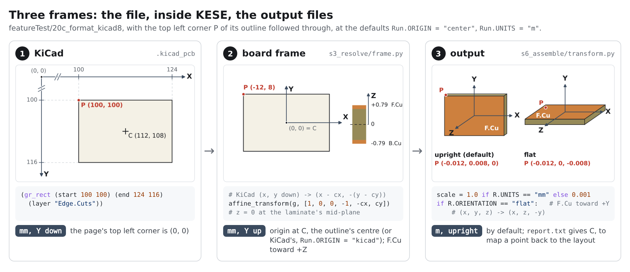
| Frame | Where | Units and axes | Origin |
|---|---|---|---|
| KiCad | the .kicad_pcb file |
mm; X right, Y down | the page's top left corner |
| Board | inside KESE, stages 3 to 6 | mm; X right, Y up; F.Cu toward +Z |
the outline's centre (Run.ORIGIN = "center") or KiCad's origin ("kicad"); z = 0 at the laminate's mid-plane |
| Output | the written files | mm or m (Run.UNITS); the board in the XY plane with F.Cu toward +Z (Run.ORIENTATION = "upright") or in the XZ plane with F.Cu toward +Y ("flat") |
as the board frame |
# kese/s3_resolve/frame.py: KiCad (x, y down) -> board (x - cx, -(y - cy)), on the grid
sh.snap(affinity.affine_transform(sh.polys_only(g), [1, 0, 0, -1, -cx, cy]))

# kese/s6_assemble/transform.py: board -> output
scale = 1.0 if R.UNITS == "mm" else 0.001
if R.ORIENTATION == "flat":      # board in XZ, F.Cu toward +Y
    rot = np.array([[1, 0, 0, 0], [0, 0, 1, 0], [0, -1, 0, 0], [0, 0, 0, 1]], dtype=float)
report.txt names the origin used, for example
origin: outline centre (112.0000, 108.0000) in KiCad coordinates, so a position in the model can
be mapped back to the layout.
| Previous | Next |
|---|---|
| Examples | Stack-Up Model |