Repository navigation
Figures
The book has 197 figures. Every one is specified by a <!-- FIGURE ... --> marker at the point it belongs in its chapter and drawn by a Python script, figures/scripts/chNN.py, from the same numbers the text uses (numpy, scipy, matplotlib; circuits, logic and timing diagrams with schemdraw). The full plan, with what each figure shows, is FIGURES.md.
pip install -r requirements.txt
python scripts/build-figures.py          # all chapters
python scripts/build-figures.py ch07     # one chapter
node scripts/insert-figures.mjs          # place newly drawn figures below their markers
npm run figures:plan                     # rebuild FIGURES.md
CI runs every figure script on each push.
| Kind | Count |
|---|---|
| plot | 49 |
| block-diagram | 39 |
| timing-diagram | 31 |
| circuit | 23 |
| waveform | 14 |
| schematic | 12 |
| flowchart | 10 |
| cross-section | 7 |
| table-graphic | 4 |
| state-diagram | 4 |
| layout | 4 |
| Ch. | Title | Figures |
|---|---|---|
| 1 | Electronic Device Fundamentals | 6 |
| 2 | Semiconductor Junction Devices | 6 |
| 3 | Bipolar Junction Transistors | 6 |
| 4 | Field-Effect Transistors | 6 |
| 5 | Advanced Semiconductor Devices | 6 |
| 6 | Diode Circuits | 6 |
| 7 | Transistor Amplifiers | 5 |
| 8 | Operational Amplifiers | 6 |
| 9 | Feedback and Oscillators | 6 |
| 10 | Analog Integrated Circuits | 6 |
| 11 | Digital Number Systems | 5 |
| 12 | Boolean Algebra and Logic Gates | 5 |
| 13 | Combinational Digital Systems | 5 |
| 14 | Sequential Digital Systems | 6 |
| 15 | Digital System Design | 5 |
| 16 | Computer Architecture | 6 |
| 17 | Microprocessors and Microcontrollers | 6 |
| 18 | Memory and Programmable Logic | 6 |
| 19 | Hardware Description Languages | 6 |
| 20 | Programming Fundamentals | 5 |
| 21 | C/C++ for Engineering | 5 |
| 22 | Python for Engineering | 5 |
| 23 | Algorithms and Data Structures | 5 |
| 24 | Scientific Computing | 5 |
| 25 | Embedded-System Architecture | 6 |
| 26 | Embedded Interfaces | 6 |
| 27 | Real-Time Computing | 6 |
| 28 | Embedded System Design | 6 |
| 29 | Power-Electronic Fundamentals | 6 |
| 30 | DC–DC Converters | 6 |
| 31 | AC–DC and DC–AC Conversion | 5 |
| 32 | Motor Drives and Power Conversion | 6 |
| 33 | CMOS Fundamentals | 5 |
| 34 | VLSI Design | 5 |
| 35 | Hardware–Software Co-Design | 6 |
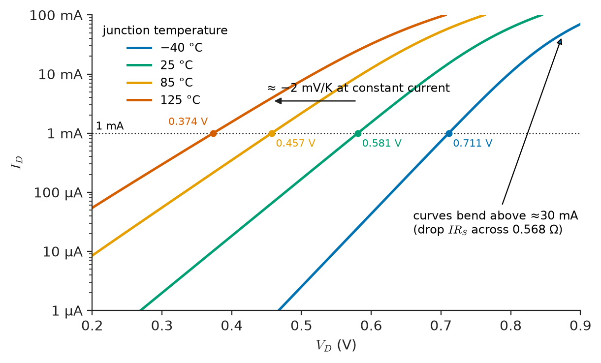
Forward characteristic of a silicon signal diode at four junction temperatures.
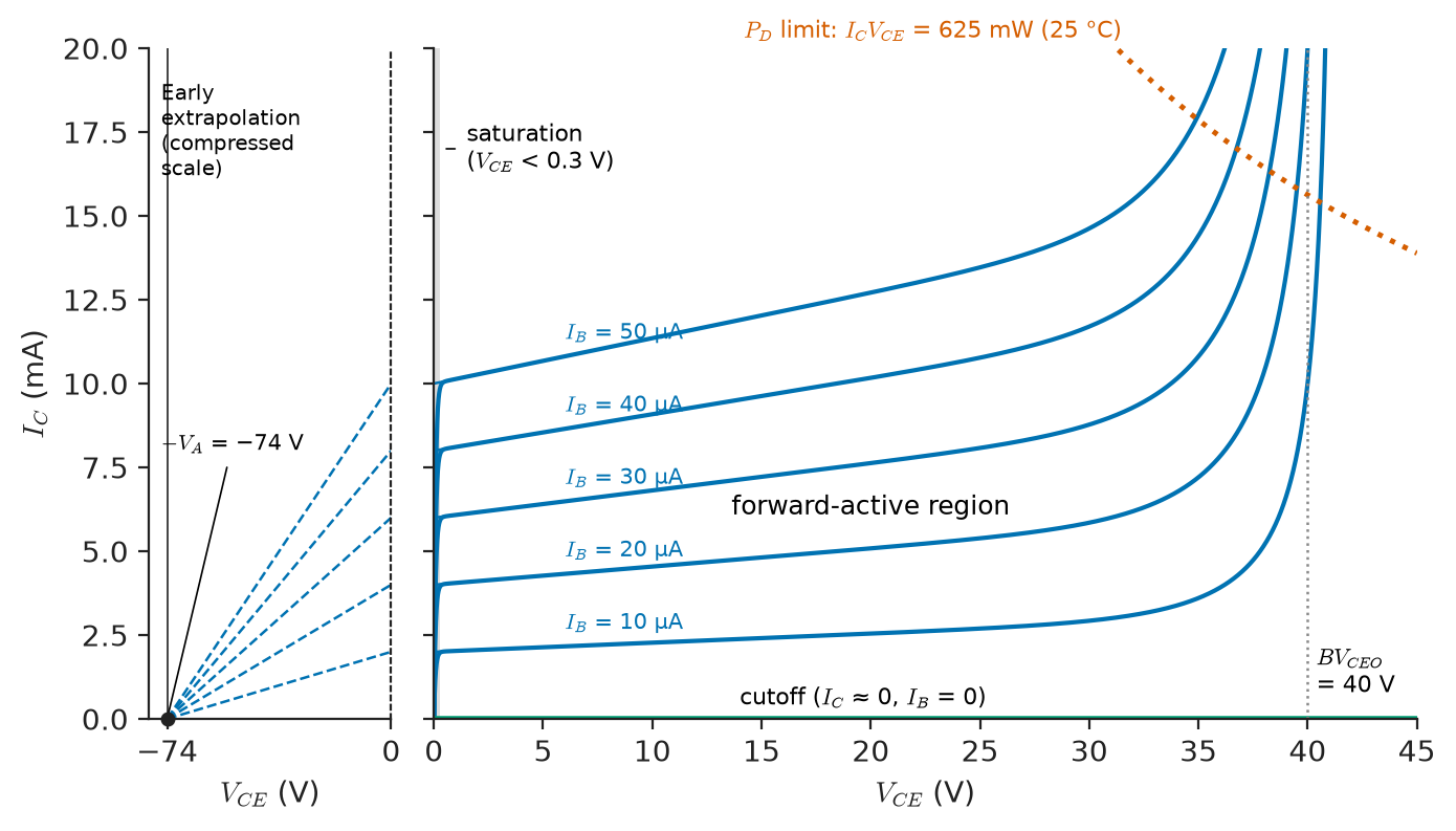
Output characteristics of a small-signal NPN transistor with operating regions and the Early-voltage construction.
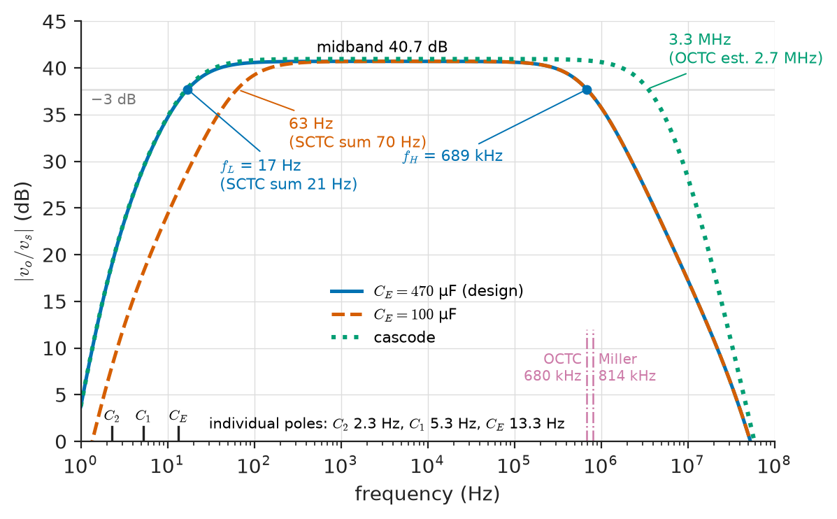
Magnitude response of the 2N3904 common-emitter stage from 1 Hz to 100 MHz, with the low-frequency poles of the coupling and bypass capacitors and the Miller-limited upper corner.
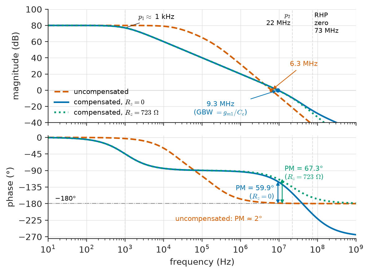
Open-loop gain and phase of the two-stage op-amp before and after Miller compensation.
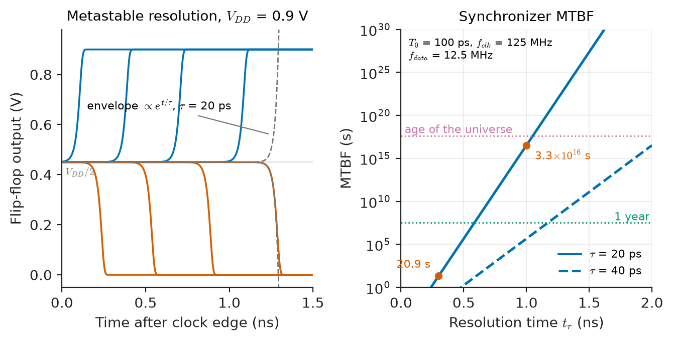
Metastable resolution of a flip-flop and synchronizer MTBF versus resolution time.
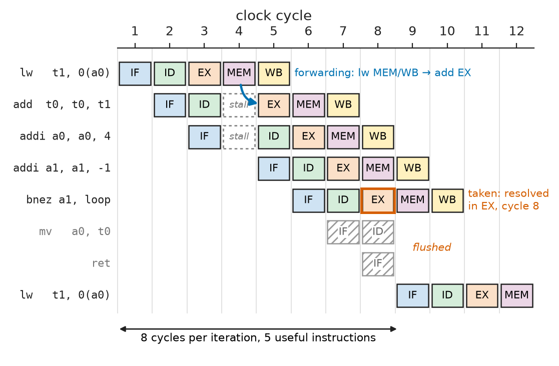
Five-stage pipeline diagram of the sum loop showing a load-use bubble and a taken-branch flush.
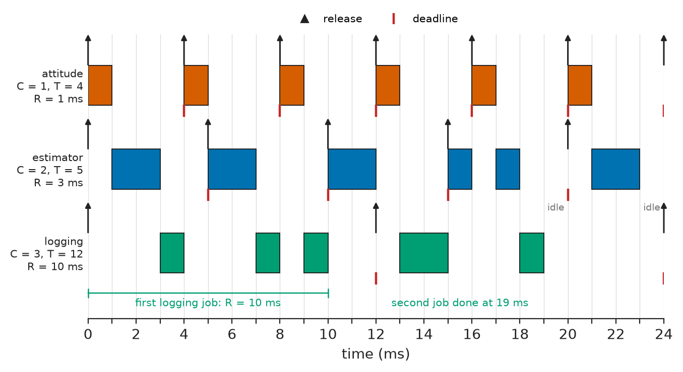
Rate-monotonic schedule of the flight-controller task set over the first 24 ms.
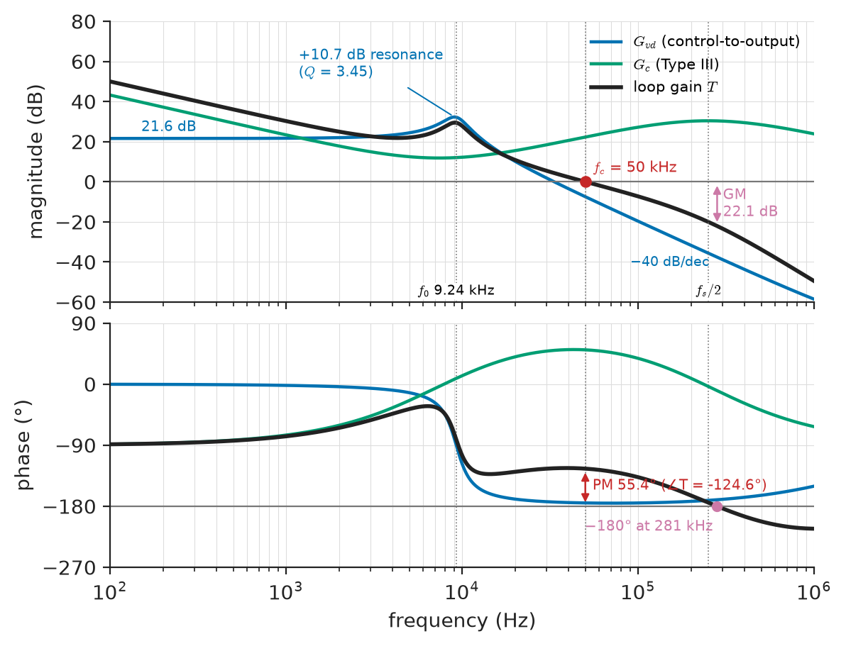
Bode plots of the buck's control-to-output response, the Type III compensator and the loop gain, with crossover and margins marked.
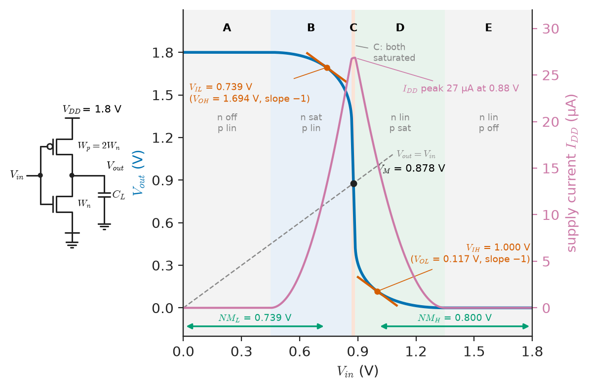
Voltage transfer characteristic of a 1.8 V CMOS inverter with its five operating regions, switching threshold and noise margins.