02_DevLab_Grove_QWIIC_STEMMA
DevLab / Grove / QWIIC / STEMMA connector area
In this lesson, you will learn how to use the DevLab, Grove, QWIIC, and STEMMA-compatible connector area included in your UNIT DevLab Multi Hub Shield. These connector ecosystems reduce loose jumper wiring and make it easier to connect sensors, displays, and other peripherals.
Although I2C is the most common use case for these compact connector ecosystems, not every connector or module is electrically equivalent. DevLab can also be used with other signal types, such as UART, PWM, WS2812/NeoPixel data, ADC/analog input, and general digital I/O, depending on the specific module and board assignment.
QWIIC and STEMMA QT use 4-pin JST-SH style wiring for I2C devices. Grove I2C modules can also be used when the cable or adapter maps the same signals correctly: VCC, GND, SDA, and SCL.
Several connector ecosystems solve the same general problem: they let you connect sensors and modules without loose jumper wiring. The main differences are the connector format, target ecosystem, voltage expectations, and how the signals are arranged.
DevLab is the UNIT Electronics connector ecosystem used to simplify module integration across UNIT boards and shields. Unlike QWIIC and STEMMA QT, which are mainly focused on I2C, DevLab connectors may be assigned to different protocols or signal types depending on the module area. Examples include I2C, UART, PWM, WS2812/NeoPixel data, CAN/TWAI, ADC/analog input, and digital I/O.
Important: Each DevLab port supports only one protocol at a time. The same physical port can be configured for different protocols (I2C, UART, CAN, RGB NeoPixel, etc.), but you cannot multiplex different protocols simultaneously on the same port. The protocol assignment depends on the specific module and board configuration.
Because DevLab can carry different signal types, compatibility must be checked module by module. A DevLab cable or connector shape does not guarantee that every DevLab module is interchangeable with every other DevLab port.
DevLab Ecosystem
Grove is a modular connector ecosystem commonly used with educational and rapid-prototyping hardware. Grove modules usually use 4-pin cables and may carry I2C, digital, analog, or UART signals depending on the module. For I2C Grove modules, the relevant signals are VCC, GND, SDA, and SCL.
Grove Ecosystem
QWIIC is SparkFun's I2C connector ecosystem. It commonly uses 4-pin JST-SH cables and is intended to reduce wiring mistakes by carrying only the I2C bus and power signals. QWIIC modules are typically designed for 3.3 V operation, so voltage compatibility should always be checked.
QWIIC Ecosystem
STEMMA QT is Adafruit's compact I2C connector ecosystem. It is physically compatible with the same small JST-SH style used by QWIIC in many cases, but module voltage support depends on the specific board. Some STEMMA QT modules include level shifting or voltage regulation, while others do not.
STEMMA QT Ecosystem
| Ecosystem | Common Connector | Typical Signals | Main Use | Compatibility Notes |
|---|---|---|---|---|
| DevLab | UNIT 4-pin JST-style connector | One protocol at a time: I2C, UART, PWM, WS2812/NeoPixel, CAN/TWAI, ADC, digital I/O, power | UNIT boards, shields, sensors, displays, and functional modules | Each port supports ONE protocol at a time - no multiplexing. Protocol depends on module configuration |
| Grove | Grove 4-pin connector | Varies by module: I2C, digital, analog, UART | Education, prototyping, and sensor modules | Use an adapter cable for I2C modules and verify signal order |
| QWIIC | JST-SH 1.0 mm, 4-pin | 3.3 V, GND, SDA, SCL | SparkFun I2C modules | Usually 3.3 V; verify voltage before connecting |
| STEMMA QT | JST-SH 1.0 mm, 4-pin | VCC, GND, SDA, SCL | Adafruit compact I2C modules | Often cable-compatible with QWIIC; verify each module's voltage support |
The important point is that I2C modules share the same basic electrical signals, but connector shape, cable orientation, supported voltage, and protocol assignment can vary. Before connecting any external module, confirm the connector type, pin order, voltage range, and expected signal protocol.
UNIT development boards are designed to simplify expansion through compact 4-pin connector ecosystems such as DevLab, Grove, QWIIC, and STEMMA-compatible modules. For this shield, I2C is the most common shared interface, but DevLab may also expose other protocols depending on the module section.
| Pin | Color |
|---|---|
| SDA | Yellow |
| SCL | Green |
| 3.3 V | Red |
| GND | Black |

Connector Colors
- Be careful with the wires in your connector; make sure the colors are correctly aligned.
- Verify the pinout for the specific UNIT Family microcontroller used by your code.
| Tarjeta | SCL | SDA |
|---|---|---|
| Dual MCU One RP2040 | 5 | 4 |
| Dual MCU One ESP32 | 22 | 21 |
| Dual MCU RP2040 | 13 | 12 |
| Dual MCU ESP32 | 22 | 21 |
| UNIT Pulsar ESP32-C6 | 7 | 6 |
| UNIT TouchDot S3 | 6 | 5 |
| UNIT Pulsar H2 | 22 | 12 |
- Verify the I2C pins for external development boards before connecting the wires to your shield.
- Grove modules may use a different physical connector format, so use the correct adapter cable and confirm the signal order.
| Tarjeta | SCL | SDA |
|---|---|---|
| ESP32 DevKitC V4 | 22 | 21 |
| Feather | 11 | 12 |
| Raspberry Pi Pico I2C0 | 2 | 1 |
| Raspberry Pi Pico I2C1 | 5 | 4 |
| Nano Board Format | 9 | 8 |
| XIAO | D5 | D4 |
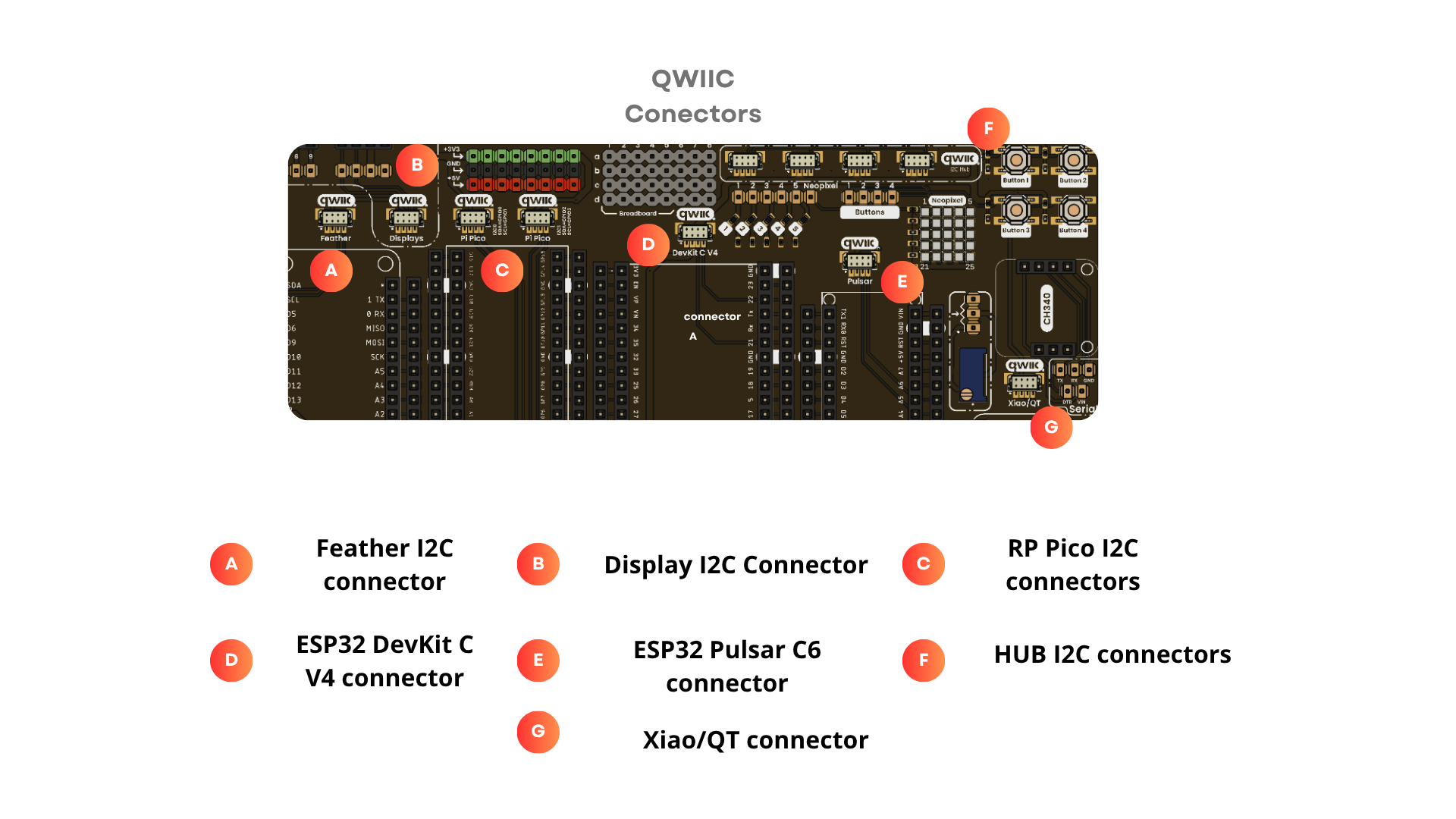
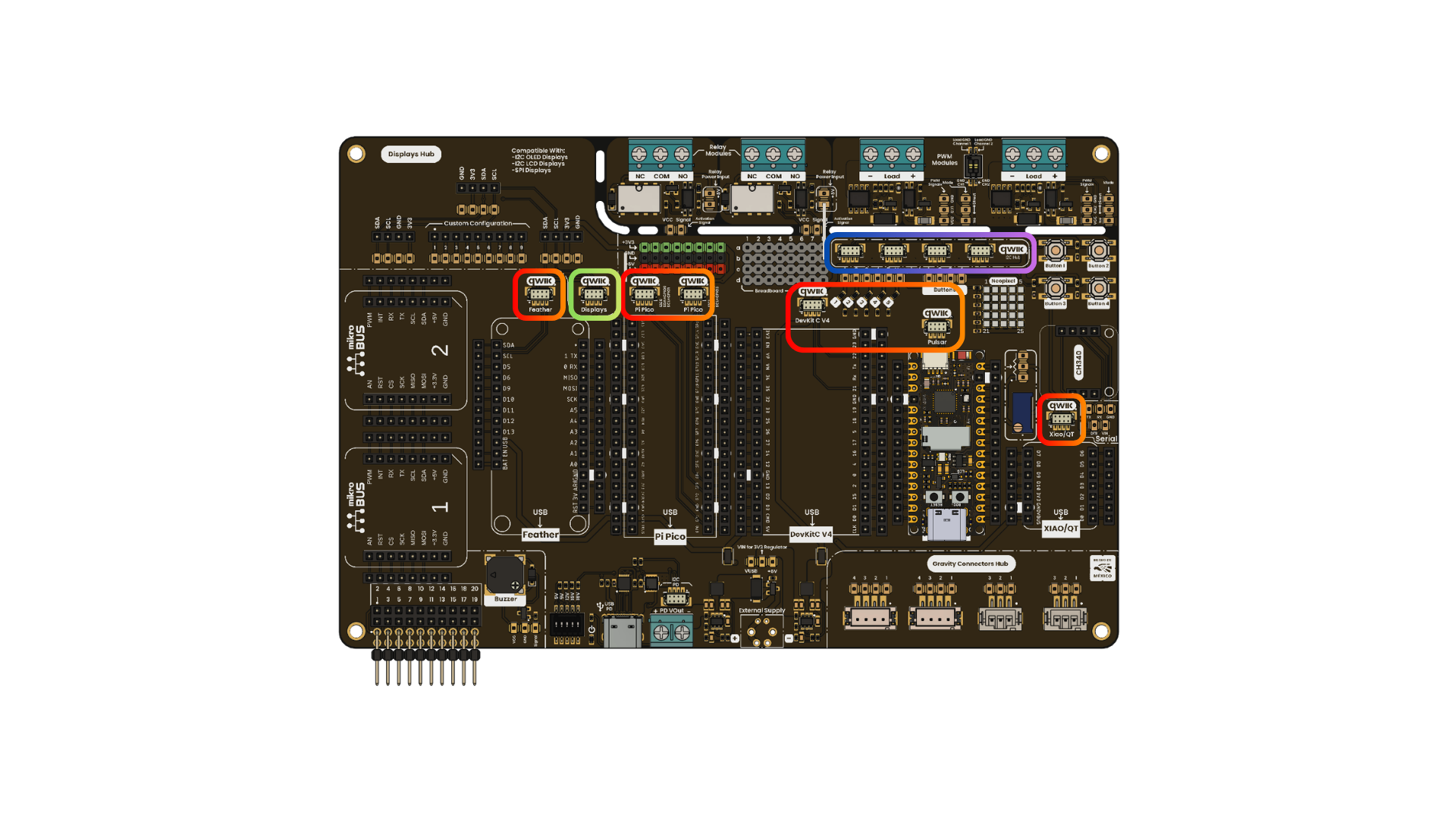
DevLab / Grove / QWIIC / STEMMA pinout
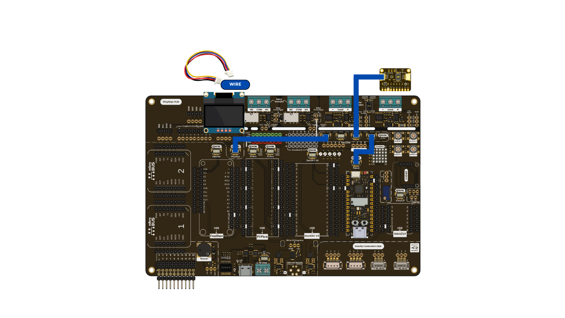
DevLab / Grove / QWIIC / STEMMA connection
#include <Wire.h>
#include <Adafruit_SSD1306.h>
#include "BMA250.h"

#define SDA_PIN 6
#define SCL_PIN 7

#define SCREEN_WIDTH 128
#define SCREEN_HEIGHT 64
#define OLED_RESET -1

// Accelerometer sensor variables
UBMA250 accel_sensor;
int x, y, z;
double temp;

Adafruit_SSD1306 display(SCREEN_WIDTH, SCREEN_HEIGHT, &Wire, OLED_RESET);

void setup() {
  Serial.begin(115200);

  // Configure I2C pins
  Wire.setSDA(SDA_PIN);
  Wire.setSCL(SCL_PIN);
  Wire.begin();

  Serial.print("I2C initialized with SDA=");
  Serial.print(SDA_PIN);
  Serial.print(", SCL=");
  Serial.println(SCL_PIN);
  Serial.println("OLED inicializada!");

  display.clearDisplay();
  display.setTextSize(1);
  display.setTextColor(SSD1306_WHITE);
  display.setCursor(0,0);
  display.print("SDA:");
  display.print(SDA_PIN);
  display.print(" SCL:");
  display.println(SCL_PIN);
  display.println("I2C BMA255 Test");
  display.println("       WELCOME");

  display.display();
  accel_sensor.begin(BMA250_range_2g, BMA250_update_time_64ms);
}
void loop() {
  delay(2000);

  accel_sensor.read();

  // Get the acceleration values from the sensor
  x = accel_sensor.X;
  y = accel_sensor.Y;
  z = accel_sensor.Z;
  temp = ((accel_sensor.rawTemp * 0.5) + 24.0);

  showSerial();
  showDisplay();
}

void showSerial() {
  Serial.print("X = ");
  Serial.print(x);

  Serial.print("  Y = ");
  Serial.print(y);

  Serial.print("  Z = ");
  Serial.print(z);

  Serial.print("  Temperature(C) = ");
  Serial.println(temp);
}

void showDisplay(){

  display.clearDisplay();

  display.setCursor(1,0);

  display.print("X = ");
  display.println(x);

  display.print("Y = ");
  display.println(y);

  display.print("Z = ");
  display.println(z);

  display.print("Temperature(C) = ");
  display.println(temp);

  display.display();
}