05_Relay_Modules
Development Board
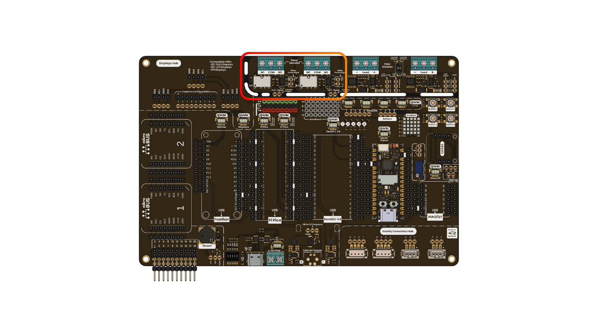
The 2-Channel G6K-2G-Y-TR Relay Modules included in your UNIT DevLab: Multi Hub Shield work as a control bridge, enabling the control of high-load devices using low-power digital signals from your microcontroller. This makes them ideal for projects requiring signal protection, such as motor control, LED lamps, and other high-power applications.
| Parameter | Description | Min | Max | Unit |
|---|---|---|---|---|
| Operation Voltage | 3.3 | 5.5 | V | |
| Input Voltage for the relay coils | 5 | - | V | |
| Maximum current per channel(Logic Input) | 2 | 15 | mA | |
| Maximum voltage to handle with the relay coils | - | 30(DC)/125(AC) | V | |
| Maximum current to handle with the relay coils | - | 1(DC)/0.3(AC) | A |
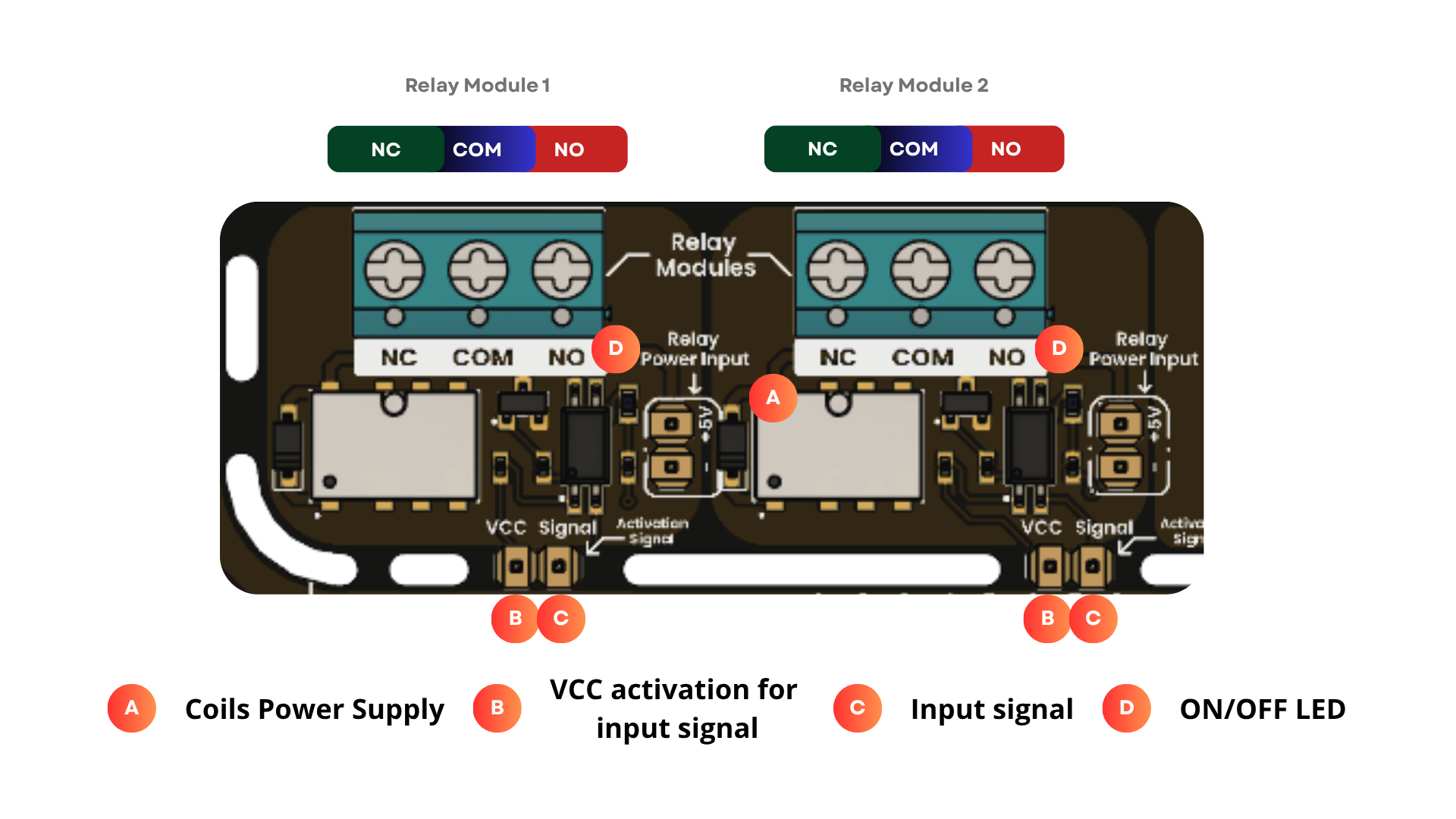
Pinout Relay Module
- 2-channel relay control for independent load switching.
- Compatible with 3.3 V and 5 V logic levels.
- Isolated control stage for improved protection between the logic side and the relay side.
- Active-low input logic:
- Input signal LOW: relay coil energized.
- Input signal HIGH: relay coil not energized.
- Ensure that the relay power input is supplied with 5 V.
- Do not exceed the voltage and current ratings of the relay contacts.
- Use a power supply with enough current for the relay coils and the connected load.
- Match the VCC logic level to the controller board:
- For 5 V logic, connect VCC to 5 V.
- For 3.3 V logic, connect VCC to 3.3 V.
- Disconnect external loads before changing wiring.
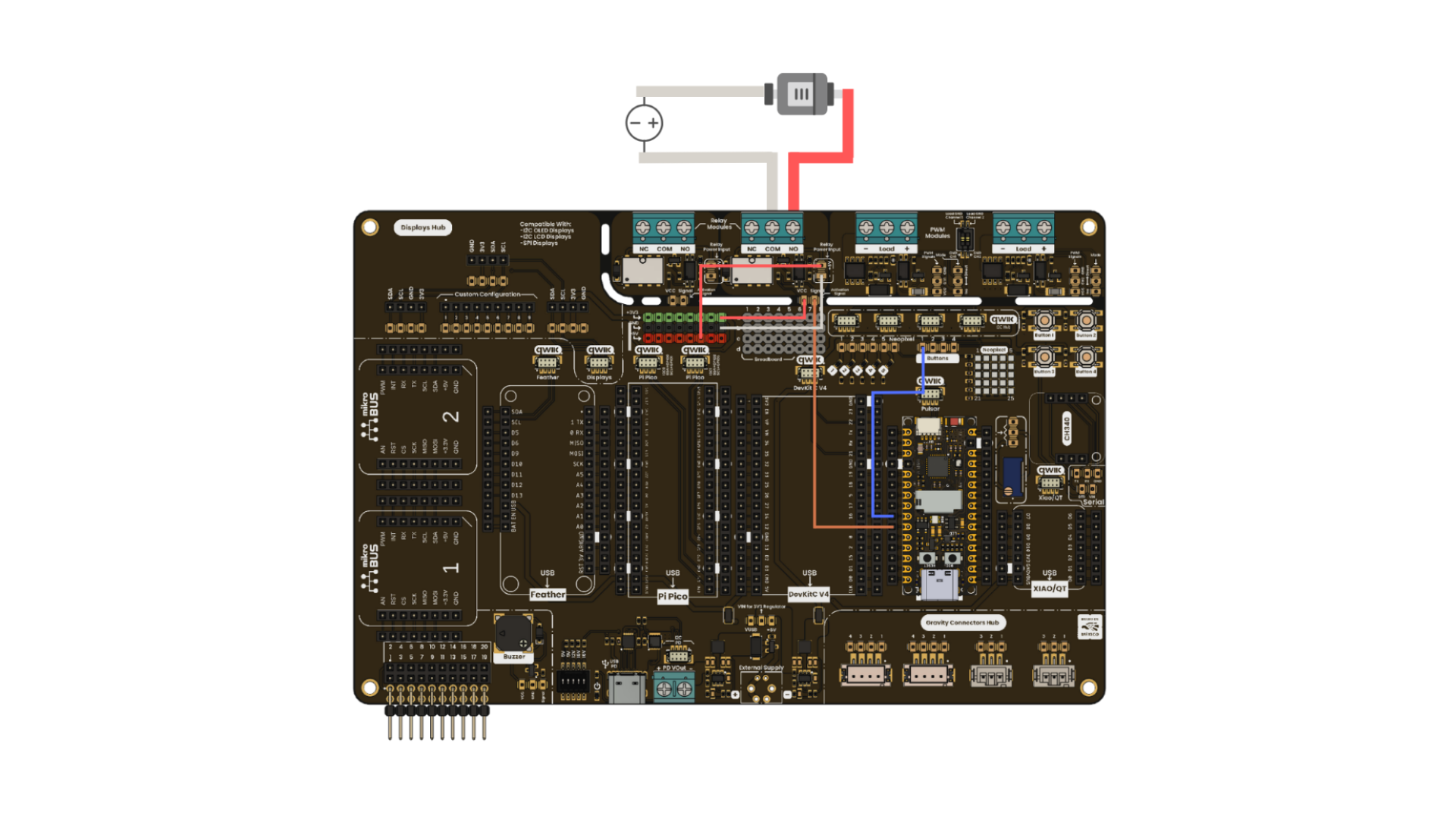
The following diagram shows the basic relay module wiring for the Arduino example. When using a 3.3 V controller, set the VIN selector to the 3V3 position.
Pin Connections
- COM (Common): Main input or reference terminal for the switched load.
- NO (Normally Open): Disconnected from COM while the relay is off. When the relay turns on, NO connects to COM.
- NC (Normally Closed): Connected to COM while the relay is off. When the relay turns on, NC disconnects from COM.
This Arduino sketch toggles one relay channel every second and prints the expected terminal state to the Serial Monitor. The relay uses active-low logic, so LOW turns the relay on and HIGH turns it off.
const int RELAY_PIN = 4;
const unsigned long INTERVAL_MS = 1000;

bool relayOn = false;
unsigned long previousMillis = 0;

void setup() {
  pinMode(RELAY_PIN, OUTPUT);
  digitalWrite(RELAY_PIN, HIGH);

  Serial.begin(115200);
  Serial.println("Relay module test started");
}

void loop() {
  unsigned long currentMillis = millis();
  if (currentMillis - previousMillis >= INTERVAL_MS) {
    previousMillis = currentMillis;
    relayOn = !relayOn;

    digitalWrite(RELAY_PIN, relayOn ? LOW : HIGH);

    if (relayOn) {
      Serial.println("Relay ON  | NO: Closed | NC: Open");
    } else {
      Serial.println("Relay OFF | NO: Open   | NC: Closed");
    }
  }
}