03_Display_Hub
The shield provides a display-oriented area for visual output and user feedback.
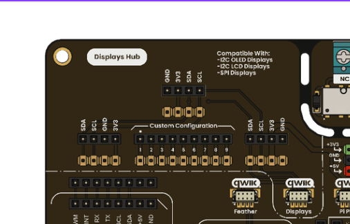
Hub to Display connection
- I2C OLED display support (128x64).
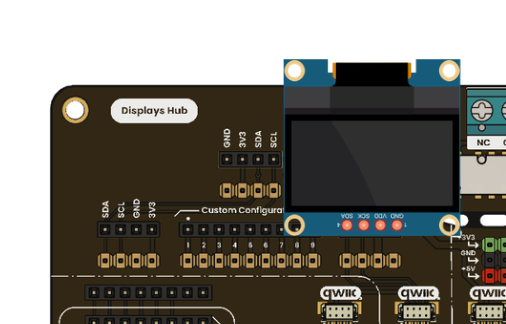
I2C OLED display
- TFT display integration support.
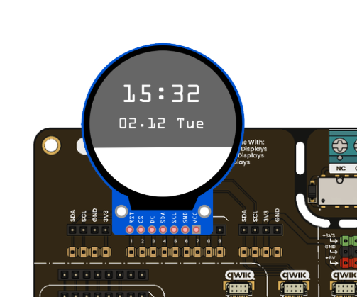
TFT display
- Sensor dashboards.
- Status and diagnostics screens.
- Menu-based UI for embedded projects.
- Confirm display voltage requirements (3.3V or 5V).
- Confirm I2C address to avoid conflicts with other devices.
OLED display connection
The DevLab / Grove / QWIIC / STEMMA connector area provides the following signals:
- VCC: 3.3 V or 5 V, depending on the board configuration.
- GND: Ground reference.
- SDA: I2C data line.
- SCL: I2C clock line.
For the Pulsar C6, the default I2C configuration is:
- SDA: GPIO6
- SCL: GPIO7
Ensure that the display module operates within the same voltage domain as the board. Incorrect voltage selection may prevent operation or damage the device.
The following example initializes the I2C interface and displays a basic message on the OLED. This confirms correct communication between the microcontroller and the display.
#include <Wire.h>
#include <Adafruit_GFX.h>
#include <Adafruit_SSD1306.h>

#define SDA_PIN 6
#define SCL_PIN 7

#define SCREEN_WIDTH 128
#define SCREEN_HEIGHT 64

Adafruit_SSD1306 display(SCREEN_WIDTH, SCREEN_HEIGHT, &Wire, -1);

void setup() {
  Serial.begin(115200);

  Wire.begin(SDA_PIN, SCL_PIN);

  if (!display.begin(SSD1306_SWITCHCAPVCC, 0x3C)) {
    Serial.println("OLED initialization failed");
    while (true);
  }

  display.clearDisplay();
  display.setTextSize(1);
  display.setTextColor(SSD1306_WHITE);

  display.setCursor(0, 10);
  display.println("Multi Hub Shield");
  display.println("Initialization OK");
  display.display();
}

void loop() {
}The program begins by initializing the serial interface for debugging. The I2C bus is then configured using the defined SDA and SCL pins for the selected platform.
The OLED display is initialized using its default I2C address (0x3C). If the display is not detected, the program stops, indicating a hardware or connection issue.
After initialization, the display buffer is cleared and a simple text message is rendered. This confirms that communication is established and that the system is functioning correctly.
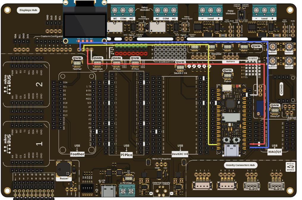
After uploading the code:
- The OLED display should power on and show the initialization message.
- The serial monitor should not report errors if the device is correctly connected.
- If no display output is observed, verify the wiring, I2C address, and voltage compatibility.
This validation step confirms:
- Correct power distribution.
- Functional I2C communication.
- Proper platform integration.
- Working development environment.
Once the initial test is successful, the system is ready for further development. Additional Multi Hub Shield features can be progressively enabled, including:
- Relay control for external loads.
- PWM signal generation for control applications.
- Sensor integration through DevLab or Gravity connectors.
- User interaction using buttons and the LED matrix.