Electronics
This section is based on the new V4 circuit boards graciously contributed by @PeteDDD. These feature a new optimized design and also integrates the TCA9548 chip as well as having both SMD and through-hole footprints giving the option to use either one.
Please refer to the legacy Electronics section if you have the legacy Gagagu version of the circuit boards.
Schematics in PDF .
Full KiCad project files here.


Image shows SMD components
All resistors, capacitors, diodes, and the transistor can be either SMD or THT components. Similarly, the TCA9548A may be a module or just the SMD chip. Use either the SMD component or the THT component for each part (not both). You can mix SMD and THT components on the board if you wish, but don't use both at the same time!
The design files include a Bill of Material (BOM) intended for PCB assembly by JLCPCB. The BOM is for the SMD components as well as all of the connectors, etc. The processor module should be purchased separately and is not included in that BOM.

Image shows through hole (THT) components
Volume control is normally not neeeded as the application uses short beeps and frequencies that is designed to not be intimidating. Start withouth this and add if necessary later.
-
Buzzer volume trimmer option: If you don't want to have the ability to adjust the volume of the buzzer, you can elect not to install the trimmer and instead install a wire jumper where "no trim" is marked on the board. Trimmer pads can accept long or square format trimmers.
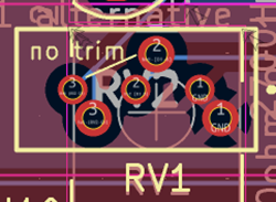
-
Buzzer enable can be a 2-pin 2.54mm pin header with a jumper cap OR if you do not want the ability to disconnect the buzzer, can just be a jumper wire.
-
Buzzer pads can accept buzzer with 6mm or 5mm connector spacing. Other pitch sizes may fit with some bending.
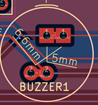
-
D1/D2 is no longer recommended, leave empty.
-
On-board reset button is optional but convenient to have, if you don't have an externally wired reset button. Either one of them may be necessary in order to initiate firmware upload. Sometimes this gets locked, and a double tap on reset fixes that. I suggest an external reset button for conveniance.
-
TCA9548A (I2C mux) cards are available with two different pin strip spacings. That is why there is a double row of pin pads on one side of the footprint. Use the set that fit your board if you are using the module instead of the SMD chip. If using the module version, it is recommended, but not mandatory, that you use a pin socket strip on the board instead of soldering the module directly to the board.
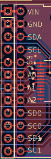
-
It is recommended, but not mandatory, that you solder a pin socket strip to the board to plug in the Pro Micro rather than solder the Pro Micro directly to the board.
A number of different connectors can been used. Pin headers, screw terminals or JST XH headers that has a keyed orientation and is reliable (recommended). Any type of header with a pin pitch of 2.54 can be used. You can even solder directly to the board but it is not recommend since wires can sometimes break from repeated bendings and being able to easily replace them is nice. The drawback of using screw terminals is that wires can become loose. And keeping track of which wires goes in what terminal can be challenging.
The panel header connects to the following:
- Power on LED (5V)
- An "error" LED. It is connected in parallel to the buzzer and has the same signalling as the buzzer. The buzzer is used for signalling both positive and negative feedback with the pitch (frequency) of the sound and the LED cannot fully convey that, so it is recommended that a buzzer is used.
- Calibration button
- Reset button. The boot loader in the Arduino Pro Micro has been a bit iffy at times when uploading the firmware. This might be because the processor is busy sending data on the USB serial port all the time. However, if the microcontroller is resetted 2 times within 8 seconds the bootloader will initialize and the upload works every time.
Note
Minus pin to the "flat side" of the LED.
The buzzer must have the correct leg to ground (The positive terminal of the buzzer is normally marked with a '+'). There are many options as long as it is 5V and a passive model. If you use a buzzer rated for higher than 5V the volume may be too low.
While the selection of a passive buzzer should be easy, we have tried many that did not perform well. The buzzer should be a passive one (requiring a square wave input) and not an active one (which normally just uses a DC voltage). One that does work well is the Jiangsu Huaneng Elec QMB-09B-03 which is available from JLCPCB/LCSC as part number C96256 or from Aliexpress (in bag of 50 pieces) https://www.aliexpress.us/item/3256807037647478.html.
Another option is to use an Arduino "buzzer module", which has been used in the build in pictures. It fits the specs perfectly, but you need to bend the legs to get it to fit on the PCB, but it works well despite. E.g AZDelivery KY-006
The buzzer's volume can be adjusted using RV1 and muted by removing the BUZ ENABLE jumper. Depending on which RV1 you use, and the direction you mount it, increasing the volume may require a counter-clockwise or clockwise turn of the screw.
The Pro Micro Processor Module is used on this board. You can use the Sparkfun Pro Micro or some of the Generics. Take care to use only the 5V 16MHz version.
The microcontroller module can be soldered to the board directly, but it is recommended to use female pin headers or a socket so it can be removed if faulty.
The PCB has two options for the TCA9548 I2C multiplexer chip:
- Using a commonly available TCA9548 I2C module and soldering the module directly on the board
- Soldering the surface mounted TCA9548 IC to the U1 position on the board. This option is to be used also if the board is orderered with components placed and mounted by the factory.
The modules are available with the pin rows at two different distances apart depending on the source of the module. The pinouts are the same. The PCB can accomodate either width of module.
Important
Please note that the R1 resistor needs to be removed (desoldered) in order for the module to work with 5V!

The roll patch panel serves to centrally connect all the wiring from the Left and Right IR sensors and the roll encoder of the frame. A common cable is then routed via the cable chain to the main PCB.

This is documented further in the Wiring section
If soldering yourself, place the 16 pcs of 0603 size 10K resistors on their positions. The two 74HC165D smd type ICs are placed accordingly.


Note
Take note of the orientation of the ICs (the dot).
I soldered the wires from the yoke buttons directly, but consider using connectors here as well for a better result.

For the main cable through the yoke tube I would recommend using a connector. A standard pin header (dupont) variant works fine here, JST XH is another option.
Tip
Make the slotted hole in the yoke tube where the cable exits just large enough so you can slide this connector through for easy maintenance when needed.

Please refer to the Yoke Controller section for wiring instructions.
The two BTS7960 modules has their own 24 V feed from the power supply. Two things about that feed are worth knowing.
The IBT-2 module already carries a 330 uF 50 V electrolytic, but that part is there to steady the rail against PWM switching ripple, and it is far too small to swallow a whole winding's worth of stored energy. Add an electrolytic across the driver's 24 V input, right at the B+ / B- screw terminals and with short leads: a few thousand uF (2200-4700 uF), low ESR, rated 35 V or more. It sits in parallel with the on-board one and does the heavy lifting.
The reason is what happens when the H-bridge lets go. If the firmware releases the bridge while the motor is still carrying current - which it does the moment a strong effect stops - that current cannot stop instantly, because the winding is an inductor. Its only path is backwards through the transistors' built-in diodes and into the 24 V rail. A switch-mode power supply cannot absorb current arriving at its output, so the rail climbs until the supply trips on over-voltage and shuts down. The capacitor gives that energy somewhere to go.
Note
This was measured, not theorised. On a 20 A supply, stopping a strong effect shut the PSU down every single time. A 10 A supply had hidden the same fault for months by limiting the current - the energy involved grows with the square of the current, so twice the current is four times the kick.
How far the rail rises depends on how much capacitance is there to catch the energy
(V = sqrt(V0^2 + 2E/C)), and 330 uF is roughly a fifteenth of what is needed:
| capacitance | 10 A in the winding | 15 A | 20 A |
|---|---|---|---|
| 330 uF, on-board only | 27 V | 30 V | 34 V |
| 330 + 2200 uF | 24.4 V | 24.9 V | 25.6 V |
| 330 + 4700 uF | 24.2 V | 24.5 V | 24.8 V |
Note
Those figures assume a winding inductance of about 0.5 mH, which is typical for this class of motor but was not measured on these, so read them as orders of magnitude rather than predictions. They do line up with what happened: with the on-board capacitor alone the rail reaches the 29-34 V where a 24 V supply trips on over-voltage, and passes the BTS7960's own ~27 V rating on the way. A few thousand uF keeps the rise under a volt.
The firmware now brakes the motor for 10 ms before releasing the bridge (COAST_BRAKE_MS in
defines.h), which lets the current die away inside the motor and cured the shutdowns on its
own. The capacitor is belt and braces on top of that - and it is what protects you if you
ever run a build without that fix, or disable COAST_AT_IDLE.
Caution
A few thousand uF draws a heavy inrush current at switch-on. Expect a spark at the connector if you attach the power cable to a running PSU. Use a switch rated for it - repeated arcing pits switch contacts.
Gagagu has made a detailed documentation of the ordering process of PCBs and mounted components in the legacy version of the Electronics guide. This can be used as a guideline as how to order, but keep in mind that the new boards has different BOMs.