Firmware
The 775 DC motors do not respond smoothly to small commands. Everything in the drivetrain - brushes, bearings, the belt, and the planetary gear if the pitch axis still has one - has stiction: it takes noticeably more push to get the axis moving than it does to keep it moving. Below a certain motor power nothing happens at all, and the instant that threshold is crossed the resistance drops away and the axis breaks loose with a lurch.
That matters because most of what you actually feel in a flight sim lives at the bottom of the force range: the centre of a spring, a light trim offset, gentle turbulence, the first hint of aerodynamic load. A motor that ignores the first 10 % of the range and then jumps is exactly wrong for that.
Three settings shape the low end. They are all in src/defines.h and take
effect when you compile, plus one slider in the Settings Tool. You do not have
to touch any of them - the defaults are a reasonable starting point - but if the
yoke feels dead around centre, or grabby, or hums when you let go, this is where
to look.
Note
These settings arrived in firmware 1.0. Older builds only have the Motor Start PWM slider described below.
In the Settings Tool, each axis has a Motor Start PWM slider. It is the motor power at which that axis just overcomes its own friction - its breakaway point. Set it too low and the axis ignores small forces; too high and it oscillates around the centre of a spring.
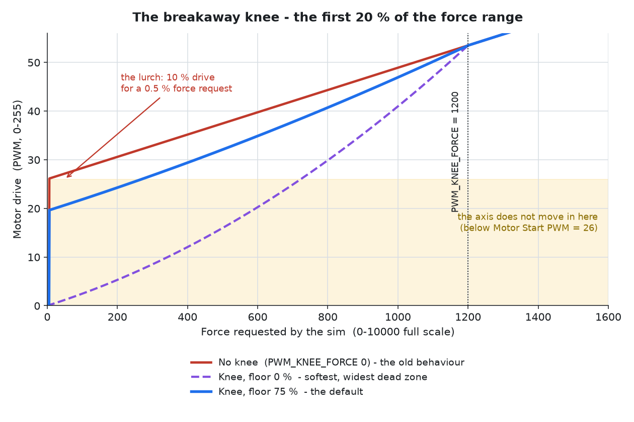
Originally the firmware jumped straight to this value the moment any force was requested, however small. A 0.5 % force request produced about 10 % motor drive. That is the lurch, and it is the red line below.
Motor Start PWM is a Settings Tool slider, so it applies immediately - you can sweep it while the yoke is running, with no recompiling.
The catch is that the two settings described further down deliberately change how much drive a small force produces, so you cannot measure breakaway while they are active. Turn them off for the measurement, then put them back:
#define PWM_KNEE_FORCE 0      // temporarily, for this measurement only
// #define ENABLE_FRICTION_FF // temporarily commented out
With those out of the way, use the FFB Test Tool
(bundled at tool/other/FFBTestTool.exe), disable the Spring force
and send a Constant Force at magnitude 100, duration infinite - direction 90
or 270 for roll, 0 or 180 for pitch. That is small enough that almost all of the
drive is Motor Start PWM itself, which is exactly what you want to be measuring:
| Requested magnitude | Motor drive, knee and assist off |
|---|---|
| 50 | Motor Start PWM + 1 |
| 100 | Motor Start PWM + 2 |
| 300 | Motor Start PWM + 6 |
| 500 | Motor Start PWM + 10 |
Now raise the slider a count at a time, hands off the yoke, until the axis just begins to creep. That is breakaway for that axis. Nudging the yoke may be necessary to get a fell for which count the axis starts to move at. Find a sweet spot per axis and direction (use both forward and reverse on each axis) where the axis just starts to move, not where it is moving all by itself.
Tip
Friction is not the same all the way along the travel. Check at a few positions across the range and in both directions, and use the highest value you find, or the axis will stall in the stiff spots.
For comparison, that same magnitude-100 request with the knee and the assist at their defaults produces a drive of about 39 on roll and 42 on pitch, against 41 and 45 with both switched off. The knee holds the small stuff back and the assist gives some of it back, so measuring with them enabled would set Motor Start PWM a couple of counts high - less misleading than it used to be, but still worth turning them off for the measurement.
Instead of stepping straight to Motor Start PWM, the firmware now eases into it
along a curve, over the first PWM_KNEE_FORCE units of requested force. Weak
effects get weak drive. Above the knee nothing changes at all - the mapping is
exactly what it always was, so full-strength effects feel identical.
#define PWM_KNEE_FORCE 1200 // units of DirectInput force, 0-10000- Larger - the ease-in is spread over more of the range. Use this if the low end still grabs.
- Smaller - sharper, closer to the old behaviour. Use this if the centre feels dead or vague.
-
0- disables the knee entirely and restores the original hard step.
The knee has a side effect. If the drive ramps up all the way from zero, the smallest commands now sit below breakaway - so instead of a hard grab you get a small dead zone where nothing moves at all. Look at the purple line in the diagram above: it stays inside the shaded band for the first 700-odd units of the force range, moving nothing at all.
PWM_KNEE_FLOOR_PCT sets where that ramp starts, as a percentage of Motor Start
PWM. It is the dial between the two problems:
| Value | Behaviour |
|---|---|
0 |
Full soft ramp from zero. Widest dead zone, but no pop at all. |
80 |
Default. Most of the dead zone removed; a small pop as the axis frees. |
100 |
Hard step. No dead zone, full grab. |
#define PWM_KNEE_FLOOR_PCT 80The "pop" is the axis crossing from standing still to moving, where the friction suddenly drops. The knee and the floor can only trade one artefact against the other, because neither of them knows whether the axis is already moving. Which brings us to the third setting.
The friction holding a stationary axis is much higher than the friction acting on one already in motion. So rather than carry a large standing offset for every command, the firmware can add a small extra push that is strongest at a standstill and fades away as the axis picks up speed. It uses the axis speed the force loop already measures - no extra sensors, no extra wiring.
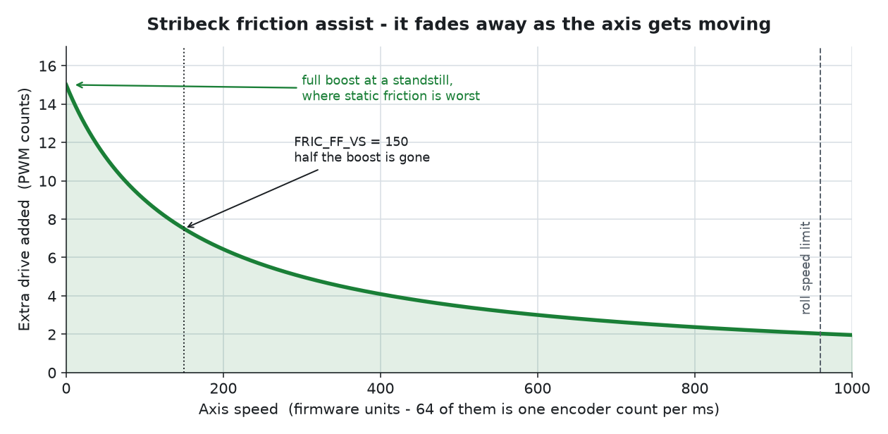
This is what lets the low end be both tight and linear. Weak effects break the axis loose, and once it is moving the assist gets out of the way.
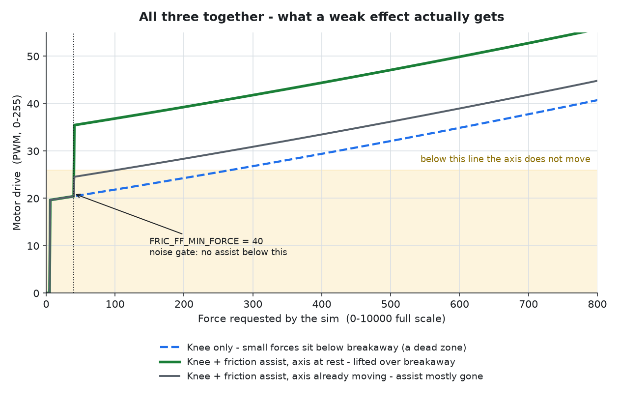
The green line is a weak effect with the assist helping at a standstill - it clears breakaway as soon as it is past the noise gate, at a requested force of 40. The blue dashed line is the same effect without the assist: it sits in the dead zone doing nothing until the sim asks for 270, nearly seven times as much.
#define ENABLE_FRICTION_FF              // comment out to disable
#define FRIC_FF_STATIC_ROLL     6       // peak boost, PWM counts
#define FRIC_FF_VS_ROLL         200     // speed at which the boost has halved
#define FRIC_FF_MIN_FORCE_ROLL  40      // noise gate - no boost below this force
These are the roll values. The pitch trio (FRIC_FF_STATIC_PITCH and friends) lives
in the pitch drivetrain block, because both of them depend on the pulleys and gearing:
the speed is in encoder counts and the boost in PWM counts.
-
FRIC_FF_STATIC_*is the size of the assist. Raise it until small forces feel alive. -
FRIC_FF_VS_*is how quickly it fades. The default keeps it close to a standstill; raise it (up to about 256) if the axis chatters as it breaks free. -
FRIC_FF_MIN_FORCE_*stops rounding noise from producing any assist at all.
Warning
FRIC_FF_STATIC_* must stay below the real breakaway point - that is, below
your Motor Start PWM. If it does not, the assist on its own is enough to move
the axis, and the yoke can creep or hum with your hands off it. Tune this one
hands-off and stop as soon as you see or hear any movement with no effect
playing.
One more thing affects how the low end feels. With no force commanded at all, the motor driver used to leave both of its inputs low, which shorts the motor terminals and brakes it electrically. That drag fights every one of the settings above, and you feel it as a heaviness when moving the yoke by hand.
#define COAST_AT_IDLE // comment out for the old always-braked behaviourWith this enabled the driver is released when nothing is being asked of it, and the axis coasts freely. Commenting it out gives a yoke that settles more firmly when you let go, at the cost of dragging on every hand input.
Use the bundled tool/other/FFBTestTool.exe, with the Spring force disabled so you
are feeling one effect at a time.
The settings interact, so change one thing at a time and in this order:
- Motor Start PWM first, in the Settings Tool, per axis - see Measuring it above. Briefly disable the knee and the friction assist, send a Constant Force at magnitude 100, and find the lowest slider value that reliably moves the axis. Everything else is expressed relative to this, so it is worth getting right before touching anything else.
-
PWM_KNEE_FORCEnext. Fly with a light spring and gentle turbulence. If small inputs still arrive as a jolt, increase it; if the centre feels vague, decrease it. -
PWM_KNEE_FLOOR_PCTto taste - lower for smoothness, higher for immediacy. -
FRIC_FF_STATIC_*last, and hands off the yoke. Raise it a couple of counts at a time and stop before anything creeps or buzzes on its own.
Note
These four are compile-time settings rather than Settings Tool sliders, so changing them means recompiling and uploading. That is deliberate: they describe the mechanical build - motors, belt, gearbox condition - rather than a per-flight preference, and they are not expected to change once a yoke is tuned.
| Setting | Default | Where | What it does |
|---|---|---|---|
| Motor Start PWM | 39 roll / 43 pitch | Settings Tool | Motor power at which the axis breaks free |
| Total gain | 100 roll / 70 pitch | Settings Tool | Overall strength of that axis |
PWM_KNEE_FORCE |
1200 |
defines.h |
How much of the force range the ease-in covers |
PWM_KNEE_FLOOR_PCT |
80 |
defines.h |
Where the ease-in starts, as % of Motor Start PWM |
ENABLE_FRICTION_FF |
enabled | defines.h |
Speed-aware breakaway assist |
FRIC_FF_STATIC_* |
6 |
defines.h |
Size of that assist, in PWM counts |
FRIC_FF_VS_* |
200 |
defines.h |
How quickly the assist fades with speed |
FRIC_FF_MIN_FORCE_* |
40 |
defines.h |
Below this requested force, no assist |
COAST_AT_IDLE |
enabled | defines.h |
Release the motor driver when idle |
COAST_BRAKE_MS |
10 |
defines.h |
Brake the winding briefly before releasing it |
NEW_PITCH_CONF_14T |
true |
defines.h |
Which pitch drivetrain is fitted |
PHYSICS_SAMPLE_MS |
10 |
defines.h |
Window the axis speed is measured over |
ENCODER_SLOW_FILTER |
3 |
defines.h |
AS5600 output filter; 3 = fastest, 0.286 ms |
DAMPER_LPF_HZ / FRICTION_LPF_HZ
|
12 |
defines.h |
Smoothing of those two effects |
INERTIA_LPF_HZ |
8 |
defines.h |
Smoothing of inertia |
The pitch axis exists in two builds, and the firmware has to know which one it is
driving. One line in src/defines.h selects it:
#define NEW_PITCH_CONF_14T true   // true  = 14T pulleys, no planetary gear (current)
                                  // false = two 30T pulleys + 1:3.7 planetary (previous)
Everything that differs between them sits in the block directly below that line, so there is nothing else to change. Two things drive all of it:
- Counts per millimetre. The encoder magnet rides the idler pulley, so one turn of that pulley is one belt circumference: 70 mm on a 14T HTD-5M pulley against 150 mm on a 30T. The 30T build therefore reports about half the encoder counts for the same hand movement, and every setting measured in counts - velocity, acceleration, the friction delta, the speed limiter - is scaled to match.
- Force at the carriage. Force is motor torque times gear ratio divided by pulley radius. The 30T build with its 1:3.7 planetary produces roughly 1.7x the force for the same motor drive, so Motor Start PWM, gain and the calibration limits are scaled down.
Important
After switching, re-run calibration - the stored travel is in encoder counts and
those change scale - and reset the Settings Tool to defaults, because Motor Start PWM
and gain live in EEPROM and the values in defines.h only seed a yoke that has none.
The 30T figures are calculated from the measured 14T ones rather than measured on that hardware, so treat them as a starting point and check Motor Start PWM by feel first.
These three effects are not driven by the sim's force directly - they are derived from how the axis is moving, which the firmware works out from the encoder. Each has a reference value that says how much movement counts as "full effect":
#define default_damperMaxVelocity_ROLL   ( 5 << VEL_SHIFT)  // speed for full damper
#define default_frictionMaxPositionChange_ROLL 50           // travel per window
#define default_inertiaMaxAcceleration_ROLL   140           // acceleration for full inertia
Lower means heavier: the effect reaches full force at a gentler movement. The pitch equivalents live in the pitch drivetrain block described above.
Two things are worth knowing before touching them:
-
The units are encoder counts, measured over a fixed window of
PHYSICS_SAMPLE_MS(10 ms). Velocity is counts per millisecond multiplied by 64; acceleration is the change in that per millisecond, times 10. Changing the window rescales all three references. - Inertia is not damper. Inertia resists changes of speed, so it bites as a movement starts and pushes back as it stops, and does nothing at a steady speed. Sustained weight through a sweep is damper's job.
Build with FFB_SERIAL_TRACE (uncomment the line in platformio.ini) and watch the
serial port at 115200 baud. Four times a second the firmware prints:
F<nPlaying>,<rxReports>,<loops>,<fxPeak>,<fyPeak>,<vxPeak>,<vyPeak>
vxPeak and vyPeak are the fastest the axis moved since the last line, in exactly the
units the references use, and fxPeak/fyPeak are the strongest force the firmware
actually produced. Sweep the yoke the way you fly, read vxPeak, and set the damper
reference to a fraction of it - a quarter to a half is a sensible starting range, since
most flying happens well below your fastest sweep. Then watch fxPeak: if it sits at
its ceiling through ordinary movement, the effect is saturating too early.
For inertia, the rule of thumb is reference = velocity change x 10 / build-up in ms.
A sweep that reaches a peak velocity of 768 in 60 ms wants about 128.
Note
loops x 4 is the force-loop rate in Hz, which is also how often the effects are
updated. It falls as more effects play, so it is worth a glance while tuning - roughly
250 Hz with ten effects and 200 Hz with fifteen on the current firmware.
Each of the three is smoothed before it reaches the motor, and the cutoffs are set per effect:
#define DAMPER_LPF_HZ   12    // damper and friction should track the hand
#define FRICTION_LPF_HZ 12
#define INERTIA_LPF_HZ   8    // acceleration is noisier, so it gets more smoothing
Lower values feel smoother but lag; higher values feel immediate but can buzz, because acceleration in particular is derived from small differences of a quantised position. The firmware re-derives the filter from the measured loop rate, so these stay honest whatever the effect count.
The microcontroller has to be a SparkFun Micro Pro or a clone which works just as well. It has to be the 5V, 16 MHz version! The firmware is compiled and uploaded by using a programming IDE (Integrated Development Environment). There are two options:
-
Microsoft Visual Studio Code with the PlatformIO extension. VS Code can be downloaded and used free of charge. Visual Studio Code with PlatformIO extension has been used under the development of this fork and provides a much more helpful interface and functionality than Arduino IDE. However, VS Code has a steep learning curve and if the intention is to just compile the firmware code and upload to the yoke, then I would suggest using Arduino IDE.
There are numerous videos on how to get started in VS Code, but here is a good YT video on the subject. -
ArduinoIDE can be used by simply renaming the topmost "src" folder to "Arduino_FFB_Yoke".
This is a more advanced option with better functionality and also integration with Git and Github.
- Download VS Code
- Download PlatformIO extension
- Get started with PlatformIO
- Download the latest release source code from the GitHub Repo found in the Release section, or use the git clone functionality in VS Code.
- Compile and Upload to the microcontroller.
- Optionally use the Serial Monitor for debugging
Arduino IDE is recommended for simplicity. It does not have all the bells and whistles of VS Code though.
Download https://www.arduino.cc/en/software/
Start the Arduino IDE and open the Library Manager.
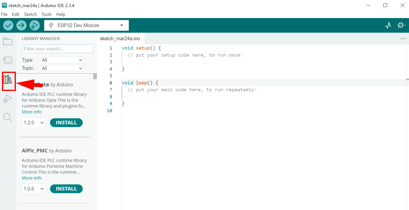
In "Filter your search", search for and install:
- AS5600 by Rob Tillaart
- TCA9548 by Rob Tillaart
- digitalWriteFast by Watterott
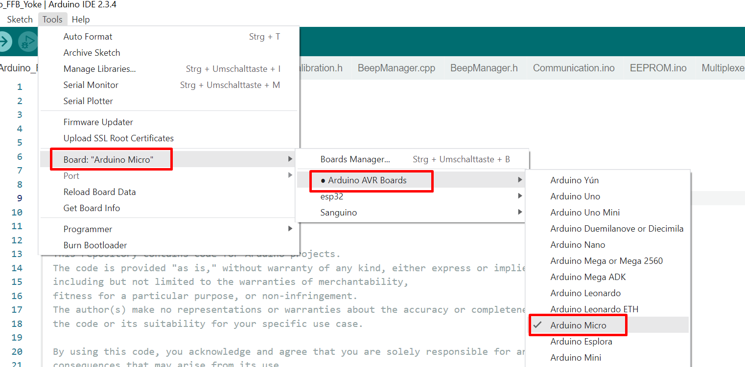
It is optional to download the SparkFun board files, the compiling will work just fine either way. But if you want to have the "proper" board configuration then follow this guide.
Important
Make sure you select the correct version of the board in the last step, i.e the 5V, 16 Mhz version!
Otherwise it is fine to use the Arduino Micro board in Board Manager, which comes preinstalled in the IDE.
Note! The screenshots used here are from an older version of the source code.
Download the latest release source code from the GitHub Repo found in the Release section. Extract the Zip file.
The Arduino_FFB_Yoke.ino is the main project file and must be in a directory with the same name (without .ino). This is very important, otherwise the compiling will not work! All other files in this directory and src directory are also needed. Simply renaming the topmost "src" folder to "Arduino_FFB_Yoke" will make the src directory compatible with Arduino IDE.

Open this file with Arduino IDE and choose the Arduino Micro Board (doesn't matter if you're using micro pro or not)
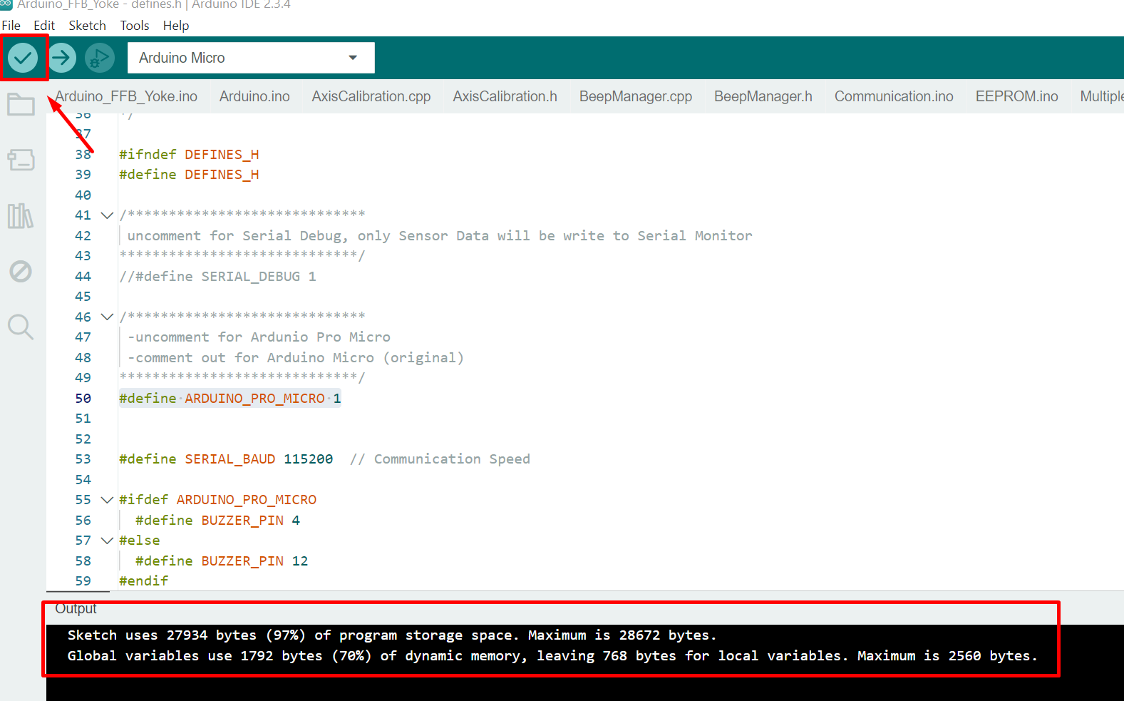
Click Verify to test if everything is all right.
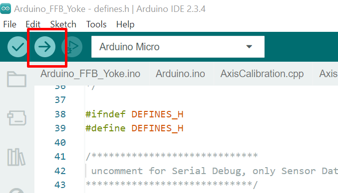
Connect the Arduino Micro Pro to the computer and choose the right COM Port.

Upload the code to the Arduino.
If you want to use multiple devices then you can change the Joystick ID in the Joystick.h file.
define JOYSTICK_DEFAULT_REPORT_ID 0x04
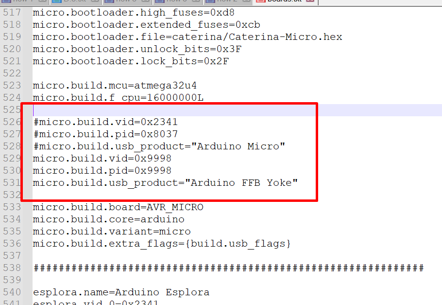
If you want to change the name of the device in the Gamecontroller list open the boards.txt file with a text editor (like Notepad++)
C:\Users<your username>\AppData\Local\Arduino15\packages\arduino\hardware\avr\1.8.5\boards.txt
find:
micro.build.vid=0x2341
micro.build.pid=0x8037
micro.build.usb_product="Arduino Micro"
and change it to (use at your own risk), you can comment out the old value by using a hash symbol
micro.build.vid=0x9998
micro.build.pid=0x9998
micro.build.usb_product="Arduino FFB Yoke"