2. Hardware
This document is meant to serve as documentation to what hardware is present in the lab, including all custom cabling.
The lab network uses the 10.0.0.x IP-range. The switch is located inside the fence to avoid tampering.
TODO: Better placement of the switch
| 10.0.0.1-99 | Everything on the gantry robot |
| 10.0.0.101-199 | Everything on the floor robot |
| 10.0.0.200-255 | Everything in the "control station" |
IP address in use 2017-12-04.
| IP | Device |
| 10.0.0.200 | Control computer |
| 10.0.0.101 | Floor robot |
| 10.0.0.103 | Floor robot RSI |
| 10.0.0.20 | Gantry robot RSI |
| 10.0.0.1 | Gantry robot |
| 10.0.0.6 | Gantry Camera |
| Gantry robot | Floor robot | |
|---|---|---|
| Controller | KRC2 Edition 2005 | KRC2 Edition 2005 |
| + expansion cabinet | ||
| KSS | 5.4.11 | 5.4.11 |
| RSI | 2.2 | 2.2 |
| Robot | KUKA KR 16 | KUKA KR 16 |
| External axes | Güdel 3 axis gantry | None |
| Force-Torque sensor | Schunk FTC-50-80 | Schunk FTC-50-80 |
| Tool change | Schunk SWS-020-K19-000 | Schunk SWS-020-K19-000 |
| Pneumatic controller | SMC EX250 | SMC EX250 |
| DC-DC SMPS | 24V, 12V & 5V, unknown model | 24V, 12V & 5V, unknown model |
| Camera | Sony SNC-RZ25P pan-tilt | None |
The pneumatic controller is currently only used for the tool-change system. There is a unused 2-way valve on both robots.
| Power supply unit 1 | GW Instek GPS-3030dd |
| Power supply unit 2 | Thandar TS3021S |
| Model | Dell Precision Tower 5810 825W Chassis |
| CPU | Intel Xeon Processor E5-1650 v3 |
| RAM | 128GB (8x16GB) 2133MHz DDR4 RDIMM ECC |
| DISK1 | Intel 360GB 2.5 inch Serial-ATA Solid State Drive |
| DISK2 | 500GB 3.5inch Serial ATA (7,200 Rpm) Hard Drive |
Please refer to https://github.com/itk-thrivaldi/Documentation/blob/master/Cables.csv for an overview of cabling in the lab
Max 50V pr pin
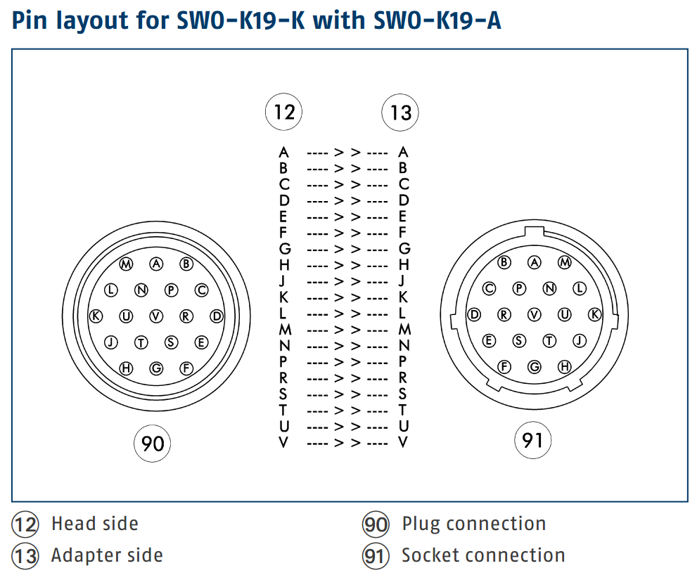
| Pin | Description | Robot side wire | Cable | From | |
|---|---|---|---|---|---|
| B | –N/C– | –N/C– | –N/C– | ||
| A | PROFIBUS | Data positive | Red | PROFI | Terminal box at Axsis 3 |
| M | PROFIBUS | Data negative | Green | ||
| C | Unused | Brown dashed | 4 TP | USB box at robot base | |
| P | Unused | Blue dashed | |||
| N | Unused | Green dashed | |||
| L | Unused | Orange dashed | |||
| D | Unused | Orange | |||
| R | 5 V | Power from robot base | Grey | 4 wire | Terminal box at base |
| V | Signal GND | Power from robot base | Yellow/green | ||
| U | 12 V | Power from robot base | Black | ||
| K | 24 V (sensor) | Power from robot base | Brown | ||
| E | Power GND | Power from controlstation | 1 | 2 wire | Terminal box at axsis 3 |
| S | Power GND | Power from controlstation | 1 | ||
| T | 24 V (tool) | Power from controlstation | 2 | ||
| J | 24 V (tool) | Power from controlstation | 2 | ||
| F | –N/C– | –N/C– | –N/C– | ||
| G | –N/C– | –N/C– | –N/C– | ||
| H | –N/C– | –N/C– | –N/C– |
| Pin | Description | Robot side wire | Cable | From | |
|---|---|---|---|---|---|
| B | Gigabit Ethernet | White/orange | TP | Control station | |
| A | PROFIBUS | Data positive | Red | PROFI | Terminal box at Axsis 3 |
| M | PROFIBUS | Data negative | Green | ||
| C | –N/C– | –N/C– | –N/C– | ||
| P | Gigabit Ethernet | Orange | TP | Control station | |
| N | Gigabit Ethernet | White/green | |||
| L | Gigabit Ethernet | Green | |||
| D | Gigabit Ethernet | White/blue | |||
| R | 5 V | Power from robot base | Grey | 4 wire braid shield | Terminal box at base |
| V | Signal GND | Power from robot base | Yellow/green | ||
| U | 12 V | Power from robot base | Black | ||
| K | 24 V (sensor) | Power from robot base | Brown | ||
| E | Power GND | Power from controlstation | Brown (split) | 2 wire braid shield | Terminal box at axsis 3 |
| S | Power GND | Power from controlstation | |||
| T | 24 V (tool) | Power from controlstation | Blue (split) | ||
| J | 24 V (tool) | Power from controlstation | |||
| F | Gigabit Ethernet | Blue | TP | Control station | |
| G | Gigabit Ethernet | White/brown | |||
| H | Gigabit Ethernet | Brown |
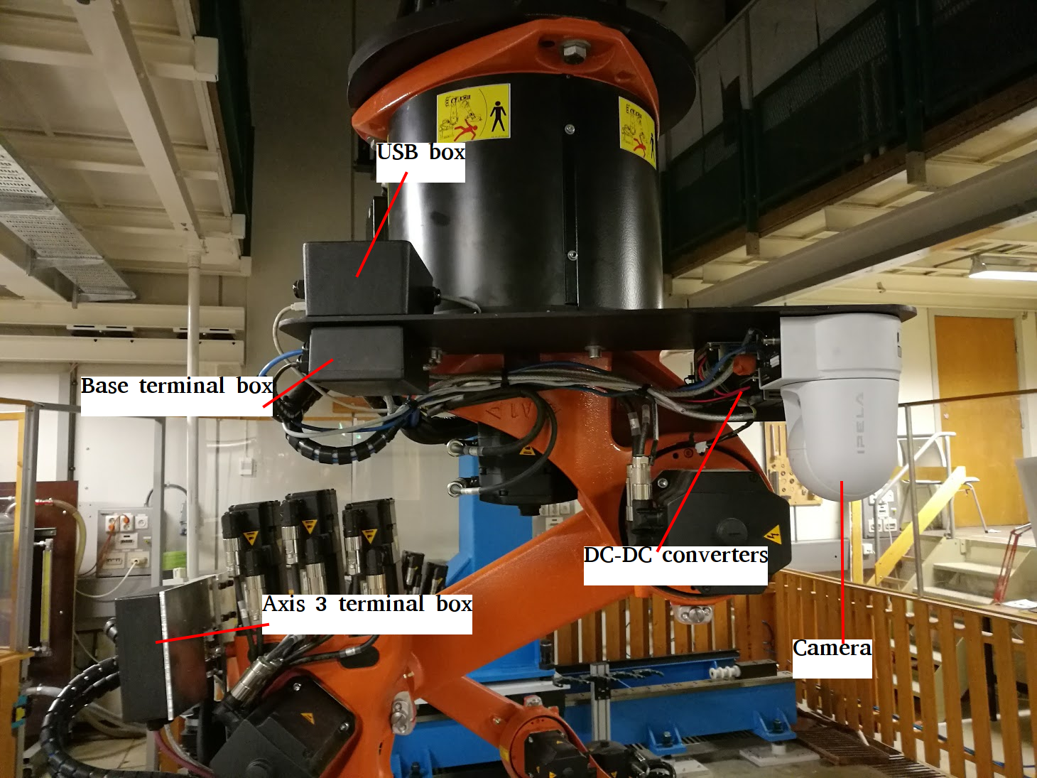
Placement of boxes are identical for both robots, apart from the USB box, which is only present on the gantry robot. Terminal box diagrams are updated to reflect the lab as of fall 2016.
Have a look in https://github.com/itk-thrivaldi/Documentation/tree/master/terminal_boxes for connection diagrams