EN‐2. Quick Start
Note
This manual is currently under development and may contain errors or incomplete information.
This section explains how to create a new ER diagram in ERD Designer.
-
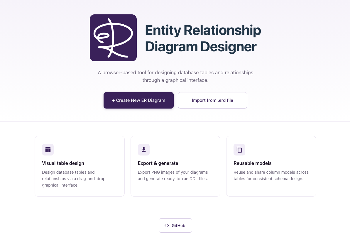
Access the Tool: Open your web browser and access kajitiluna.github.io/erd-designer.
[!NOTE] ERD Designer uses the browser's IndexedDB to save documents locally, so you may see a notification about allowing IndexedDB usage.
-
Start Creating: Click the "Create New ER Diagram" button displayed on the start screen.
-
Project Settings: Configure the following items in the displayed dialog:
- Diagram name: Enter an easily identifiable name, such as a project name or system name (e.g., "E-commerce_User_Management")
- Database: Select the target database management system (PostgreSQL, MySQL, MS SQL Server)
-
Complete Creation: Click the "Start design ER Diagram." button to display a new ER diagram canvas and begin design work.
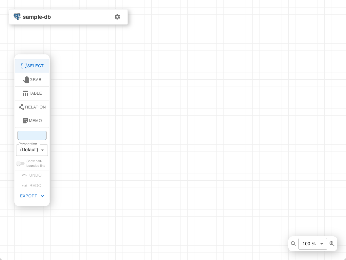
Let's learn the basic operations by actually creating a sample ER diagram. This section uses a simple blog system database design as an example.
Step 1: Create User Table (1 Minute)
-
Select "TABLE" from the left operation menu.
-
Click on an empty space on the canvas.
-
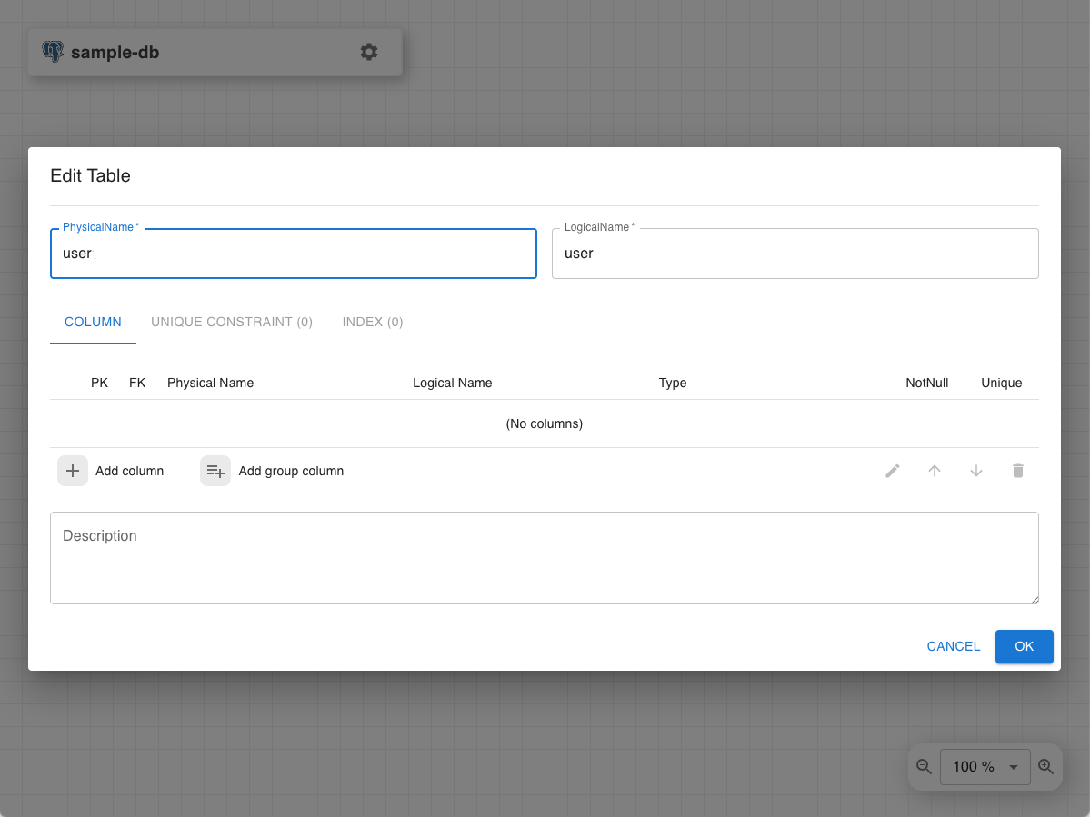
Enter "user" in the table name input field.
-
Click "OK" to confirm table creation. Alternatively, you can press Enter while the text field is focused.
Step 2: Define User Table Columns (2 Minutes)
-
Select "SELECT" from the left operation menu, or press the ESC key.
-
Double-click the created "user" table to open the table editing dialog.
-
Click the "Add Column" button to add the following columns sequentially:
user_id: Data type INTEGER, Primary Key, NOT NULL
username: Data type VARCHAR(50), NOT NULL, UNIQUE
email: Data type VARCHAR(255), NOT NULL, UNIQUE
password_hash: Data type TEXT, NOT NULL
created_at: Data type TIMESTAMP, NOT NULL, DEFAULT CURRENT_TIMESTAMP
updated_at: Data type TIMESTAMP, NOT NULL, DEFAULT CURRENT_TIMESTAMP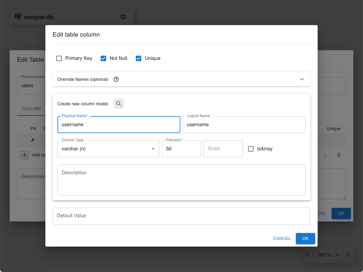
-
After configuring each column, click the "OK" button to save the changes.
Step 3: Create Post Table and Set Relationship (2 Minutes)
-
Create Related Table: Select "TABLE" from the left operation menu.
-
Click on an empty space on the canvas again.
-
Enter "post" in the table name input field.
-
Add the following columns to the post table:
post_id: Data type INTEGER, Primary Key, NOT NULL
user_id: Data type INTEGER, NOT NULL (for foreign key)
title: Data type VARCHAR(200), NOT NULL
content: Data type TEXT
published: Data type BOOLEAN, NOT NULL, DEFAULT FALSE
created_at: Data type TIMESTAMP, DEFAULT CURRENT_TIMESTAMP
updated_at: Data type TIMESTAMP, DEFAULT CURRENT_TIMESTAMP
Note that user_id has the same definition as the user_id column defined when creating the user table, so you can reuse the previous definition.
-
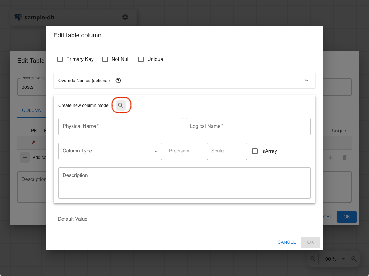
Click the "Add Column" button to display the Edit table column dialog, then click the search button located to the right of the "Create new column model." text.
-
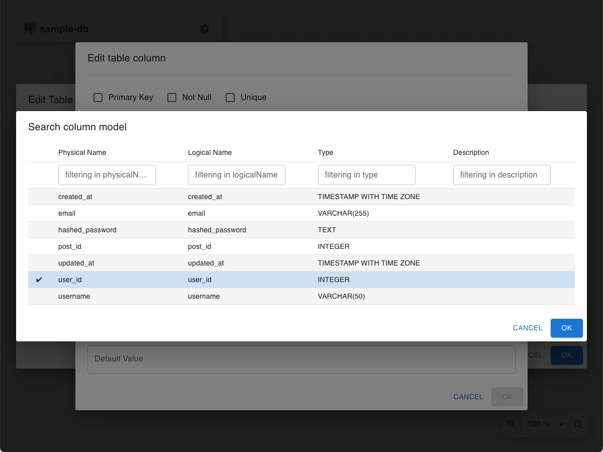
In the Search column model dialog, click to select the user_id you want to reuse, then click the "OK" button.
-
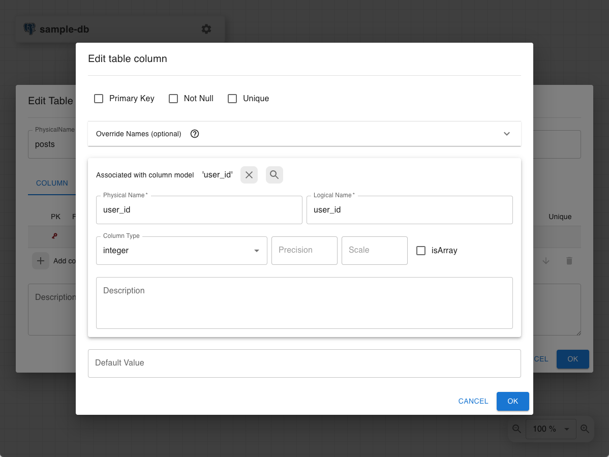
The user_id content is reflected in the Edit table column dialog. Note that Primary Key, Not Null, and Unique settings are not reused and are managed per table, so define them individually as needed.
[!NOTE] The reused column definition references the same definition as the source. In other words, if you change the user_id column definition on the post table side, the same changes will be reflected in the user_id of the user table.
-
-
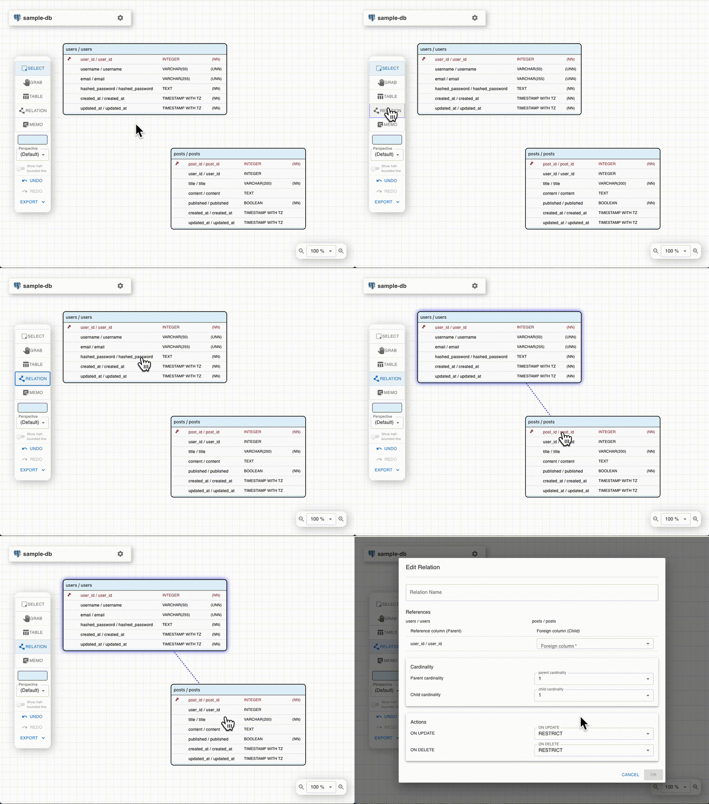
Create Relationship: Select "RELATION" from the left operation menu.
-
Press the mouse button on the user table and drag (while holding the mouse button) to the post table. Alternatively, click the user table and then click the post table.
-
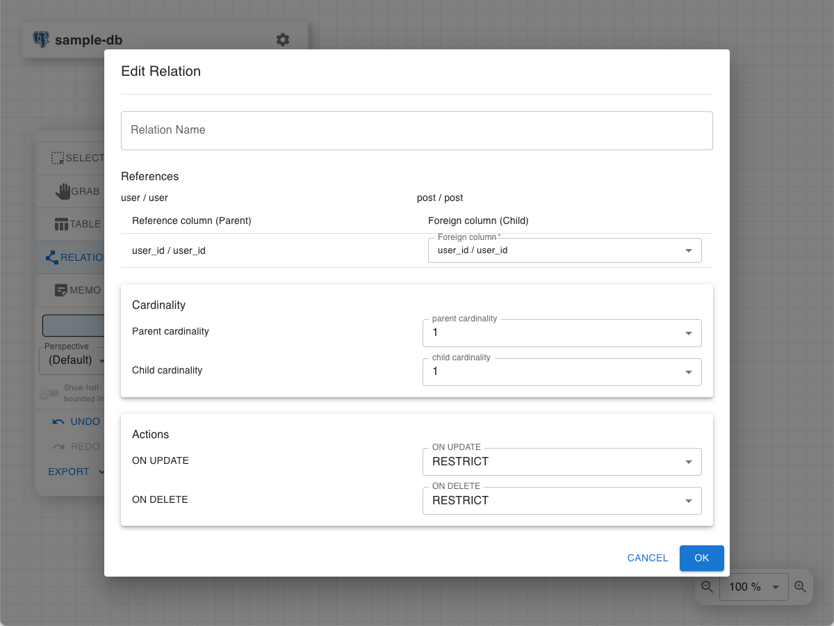
The relation settings dialog will appear, so confirm the association between "user.user_id" and "post.user_id" and click "OK".
ERD Designer has five edit modes for different purposes. You can switch modes using the panel on the left side of the screen.
- SELECT Mode: Used to select, move, and edit tables and relations (the most frequently used mode)
- GRAB Mode: Mode for freely moving the entire canvas (panning only)
- TABLE Mode: Mode for adding new tables. Clicking on the canvas creates a table
- RELATION Mode: Mode for creating relations (foreign key relationships) between tables. Create by dragging from parent table to child table
- MEMO Mode: Mode for placing memos (sticky notes) on the ER diagram. Useful for design annotations and grouping
Tip
You can work efficiently by switching modes according to your workflow. For example, when creating multiple tables consecutively, stay in TABLE mode, and switch to SELECT mode when editing or moving.
Canvas Operations
- Moving Tables: Click and drag anywhere on a table to freely change its position
- Zoom Function: Adjust using the zoom controls at the bottom right of the screen
- Pan (Screen Movement): Press and hold right-click while dragging to move the viewing area
Detailed Table Operations
- Adding Tables: Click on the canvas while in Table creation mode
- Selecting Tables: Click on a table to select it, displaying operation icons at the bottom right of the table
- Editing Tables: Double-click on a table to open the editing dialog for table name and column definitions
- Deleting Tables: Select the table to delete (click) and then press the Delete key. Related relationships are automatically deleted
Detailed Relationship Operations
- Creating Relationships: In relation creation mode, drag from the parent table (referenced side) to the child table (referencing side) to create
- Selecting Relationships: Click on the line representing the relationship to select it, displaying operation icons near the mouse cursor
- Editing Relationships: Double-click on the relationship line to change cardinality and referential integrity settings
- Deleting Relationships: Select the relationship line and press the Delete key to delete it
This section explains how to generate SQL scripts for building actual databases from designed ER diagrams.
Basic DDL Generation Procedure
-
Access Export Function: Select "Export DDL" from the "Export" menu in the menu bar.
-
Configure DDL Generation Options: Select the following options in the displayed dialog:
- Tables: Include CREATE TABLE statements (usually ON)
- Indexes: Include index creation statements (recommended for performance improvement: ON)
- Foreign Keys: Include ALTER TABLE statements to add foreign key constraints (recommended: ON)
- Comments: Include comment statements for tables and columns (recommended for documentation: ON)
- Schemas: Include schema names (valid only for PostgreSQL and MS SQL Server)
-
Set File Name: Specify the name of the SQL file to be output (e.g.,
database_schema.sql) -
Execute DDL Generation: Click the "EXPORT DDL" button to generate SQL scripts according to the settings, and file download will begin.
Tip
Generated DDL files can be executed with command-line tools such as psql, mysql, sqlcmd, or database management tools to build actual databases.
You can save designed ER diagrams as files and load them later. This is convenient for backup or migration to other environments.
Exporting (Saving) ERD Files
- Select "Save to ERD File" from the "Export" menu in the menu bar.
- Specify a file name, and it will be downloaded as an
.erdfile. - This file contains all design information including table definitions, relations, and placement information.
Importing (Loading) ERD Files
Important
ERD file import is only supported in the online tool.
- On the online tool top screen, select "Import from .erd file".
- Select the saved
.erdfile. - The ER diagram will be restored, and you can continue editing.
You can import DDL generated from existing databases to automatically create ER diagrams.
Basic Usage
- Select "Import from DDL" from the "Import" menu in the menu bar.
- Paste the DDL text.
- Set "Comment Separator" if needed (when extracting logical names from column comments).
- Click the "IMPORT" button to parse the DDL and generate an ER diagram.
Note
The DDL import feature is experimental. It may not support complex DDL syntax or some advanced features. After importing, check the generated ER diagram and manually adjust as necessary.