EN‐3. Manual
Note
This manual is currently under development and may contain errors or incomplete information.
In ERD Designer, ER diagrams are managed on a project basis. Effective project management allows you to work on multiple database designs in parallel.
Detailed New Project Creation Procedure
When creating a new project, it's important to configure settings with future extensibility and maintainability in mind.
-
Start Project Creation: Click the "CREATE NEW ER DIAGRAM" button on the start screen
-
Decide Project Name: Choose a project name that allows team members to understand the project content at a glance (e.g., "E-commerce_Member_Management_System_v1.0", "Internal_Attendance_Management_DB_Design")
-
Select Database Type: Accurately selecting the target database management system ensures that DBMS-specific data types and constraints are properly reflected
Project Saving and Auto-save Feature
ERD Designer has a powerful auto-save feature built in to prevent data loss during work.
-
Auto-save: Changes to tables and relationships are automatically saved to the browser's local storage (or the corresponding file on Google Drive for Google Drive App) upon operation completion
-
Save Location: For the online tool, data is saved in the browser's IndexedDB and is not sent online
Loading Projects and History Management
- Recent Projects: The start screen displays a list of recently edited projects. Click to quickly resume
- Loading from File: Select "IMPORT FROM ERD FILE" to restore a project from a previously exported erd file
The canvas interface is the main workspace for designing entity relationship diagrams. This section provides a detailed overview of each menu and control available in the interface.

The title panel is displayed at the top left of the interface and includes:
- Database Logo: Displays the database icon used in the currently edited file
- Diagram Name Field: Displays and allows editing of the current ER diagram name
-
Settings Button (⚙️): Access to application settings
- Perspective: Opens the perspective management screen. Allows grouping tables and memos by function or purpose and switching displays
- Column Group: Opens the column group management screen. Allows defining multiple columns together and adding them to tables in bulk
- DB Schema: Opens the database schema management screen (PostgreSQL, MS SQL Server only)
- Import from DDL: Imports ER diagrams from DDL scripts (experimental feature)

The edit mode panel is positioned on the left side and contains five primary tools:
- Purpose: Default mode for selecting and manipulating existing elements
- Usage: Click tables, relations, and memos on the canvas to select
-
Functions:
- Single click to select individual elements
- Drag to move selected elements
- Double-click to edit element properties
- Purpose: Pan and move the canvas
- Usage: Drag to move the entire canvas display
- Use Case: Useful when working with large diagrams that extend beyond the viewing area
- Purpose: Create new database tables
- Usage: Click the canvas to place a new table
- Process: Opens a table creation dialog to define table properties
- Purpose: Create relationships between tables
- Usage: Click the parent table, then click another child table to create a relationship (also possible to drag from parent table to child table)
- Functions: Supports various relation types (one-to-one, one-to-many, many-to-many)
- Purpose: Add text notes to the diagram or use as grouping boundaries
- Usage: Click the canvas to place a new memo
- Functions: Customizable text, font, color, size, foreground/background position
-
Use Cases:
- Adding design annotations and comments
- Recording important design constraints and notes
-
Foreground/Background Control:
- Foreground: Place memo in front, displayed on top of tables and relation lines
- Background: Place memo in back, used for grouping tables or dividing areas
Located below the edit mode panel, providing additional functions:
- Function: Set background color for newly created tables and memos
- Purpose: Improve work efficiency by deciding default colors for tables and memos in advance
- Function: Select created Perspectives to switch displayed tables and memos
- Purpose: Focus on specific functions or modules in large ER diagrams
- Details: See 11. Perspective section
- Undo: Revert the last action (Ctrl+Z, Cmd+Z)
- Redo: Reapply a previously undone action (Ctrl+Y, Cmd+Shift+Z)
- Visual Indicator: Buttons are disabled when no actions are available
The export button provides access to multiple export options:
-
Export DDL: Generate SQL Data Definition Language scripts
- Supported databases: PostgreSQL, MySQL, MS SQL Server
- Options: Tables, Indexes, Foreign Keys, Comments, Schemas
-
Save as Image: Export diagram as PNG image
- Use in documents and presentation materials
-
Export Specification: Generate table specification documents
- Online tool: Excel file format (
.xlsx) - Google Drive App: Google Spreadsheet format
- Contents: Table list, column definitions, indexes, foreign key constraints, etc.
- Online tool: Excel file format (
-
Save to ERD File: Output ERD Designer's native format (
.erdfile)- Used for backup or migration to other environments
ERD Designer provides rich customization options to improve work efficiency and visibility.
Detailed Display Settings Customization
-
Display Style Settings: Select display style for table names and column names
- Physical: Display physical names of tables and columns
- Logical: Display logical names of tables and columns
-
Both: Display logical and physical names of tables and columns separated by
/
-
Column Information Display:
- Key Icons: Display icons for primary keys and foreign keys
- Data Type Display: Display data type information such as INT, VARCHAR
- Constraint Display: Display constraint conditions such as NOT NULL, UNIQUE
-
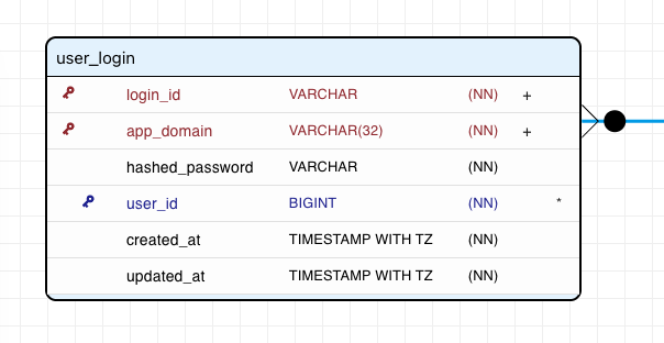
Composite Unique Key Constraint Display: Display
+on columns with composite unique key constraints -
Index Setting Display: Display
*on columns with indexes - Description Display: Hovering the mouse cursor over columns with descriptions shows a tooltip
-
Relation Line Style Settings:
- Color Settings: Improve visibility by color-coding different types of relations
- Thickness Adjustment: Set line thickness from 3 levels
- Line Type Selection: Choose from straight lines, horizontal/vertical lines
Database-Specific Settings
- Database Type-Specific Settings: Supported data types and constraints are automatically adjusted according to the selected DBMS
Themes and Coloring
- Table Color Coding: Set table background colors by function or priority
For efficient design work, you can execute main operations using keyboard shortcuts.
Editing Operation Shortcuts
| Operation | Windows/Linux | Mac | Description |
|---|---|---|---|
| Undo | Ctrl+Z | Cmd+Z | Cancel the previous operation |
| Redo | Ctrl+Y | Cmd+Y, Cmd+Shift+Z | Re-execute a cancelled operation |
| Delete | Delete, Backspace | Delete, Backspace | Delete selected elements |
In database design, tables are the basic units for storing information. ERD Designer allows you to create tables intuitively and arrange them logically.
Detailed Table Creation Procedure
-
Mode Selection: When creating a new table, press "TABLE" in the left menu to enter Create Table mode.
-
Decide Placement Position: Decide where to place the table on the canvas. Placing related table groups close together visually represents relationships.
-
Execute Table Creation: Move the mouse cursor to the placement position and click.
-
Enter Table Name:
- Physical Name: Enter the table name actually used in the database (e.g., user_accounts, product_categories)
- Logical Name: Enter names used in design documents (e.g., User Accounts, Product Categories)
-
Confirm Creation: Click the "OK" button to complete table creation. You can also press Enter while the text field is focused.
Effective Table Placement Strategies
- Grouping by Function: Place tables of related functions in close proximity (e.g., user management, product management, order management)
- Expressing Hierarchical Structure: Place parent tables higher and child tables lower to clarify dependency relationships
- Central Placement of Main Entities: Place core tables referenced by many tables (e.g., users table) near the center of the diagram
- Maintaining Adequate Spacing: Provide appropriate spacing between tables to improve visibility when drawing relation lines later
Advanced Placement Adjustment Techniques
- Multiple Selection Movement: Select multiple tables by box selection or while holding Ctrl (Cmd) key and move them together to improve placement adjustment efficiency
Setting table properties is important work that directly affects database quality and maintainability.
Detailed Basic Property Settings
Physical Name Setting Policy
- Unified Naming Convention: Adopt consistent naming conventions throughout the project (e.g., snake_case, singular form)
- Avoid Reserved Words: Avoid database-specific reserved words in names when possible
- Consider Future Extensibility: Use naming that considers the possibility of future feature additions
Utilizing Logical Names
- Setting Japanese Names: Set easy-to-understand Japanese names to facilitate communication with business personnel and non-technical staff
- Expanding Abbreviations: When using abbreviations in physical names, provide logical names that clarify their meaning
Effective Use of Description
- Table Role Description: Describe what the table manages and in what business context it's used
- Specify Constraints: Document special constraints or business rules in comments
- Record Change History: Record the background of important design changes
Schema Settings
ERD Designer supports management of schemas (namespaces) used in PostgreSQL and MS SQL Server.
Important
When setting schemas, you need to create the schema in advance. If the schema is not created, the schema edit field will not be displayed in the table edit dialog. See "Schema Management" for how to create schemas.
- Schema Role: Namespace for logically grouping tables and other objects within a database
- Setting Method: Specify schema name in the "Schema" field of the table edit dialog
-
Schema Usage Examples:
-
Functional Separation:
user_management,product_catalog,order_processing, etc. -
Environmental Separation:
development,staging,production, etc. - Permission Management: Control access permissions on a per-schema basis
-
Functional Separation:
-
DDL Output Behavior: When Schemas option is enabled, schema names are included in CREATE TABLE statements (e.g.,
CREATE TABLE user_management.users (...))
Note
MySQL treats schema and database as synonymous, so ERD Designer does not apply schema settings to MySQL.
Editing and deleting existing tables are frequent operations as designs evolve. This section explains how to perform them safely and efficiently.
Detailed Table Editing Process
How to Open Edit Dialog
- Double-click: Double-click the target table to open the edit dialog
- Operation Icon: After selecting the table, press the edit icon at the bottom right
Editable Items and Precautions
- Changing Table Name: Confirm consistency with related tables so as not to affect existing relationships
- Changing Column Structure: Changing primary keys has a major impact on foreign key relationships, so execute carefully
- Changing Constraint Conditions: Changes to indexes and constraints may affect performance
Safe Table Deletion Procedure
Confirmation Items Before Deletion
- Check Dependencies: Confirm there are no foreign keys referencing the table to be deleted
- Understand Data Impact Scope: Confirm the scope of information lost by deletion
- Confirm Backup: For important tables, confirm design data backup
Deletion Execution Method
- Select Table: Click the table to be deleted to select it
- Execute Delete Command: Click the delete icon at the bottom right
- Confirmation Dialog: Reconfirm deletion intention in the displayed confirmation dialog
- Confirm Related Deletion: Confirm that related relationships are also deleted simultaneously
After selecting a table, you can delete it without a confirmation dialog by pressing Delete key or Backspace key.
Automatic Processing During Deletion
- Automatic Relationship Deletion: All relationships related to the deleted table are automatically deleted
- Column Shared Model Processing: Column definitions exclusive to the deleted table are automatically deleted if not used elsewhere
ERD Designer allows flexible customization of table display methods according to project scale and purpose.
Color Customization
Table Header Color Setting Examples
- Color by Function: Unify colors by function such as blue for user management, green for product management
- Color by Priority: Use dark colors for core tables, light colors for auxiliary tables
Column design in database tables is important work that directly affects application quality and performance. ERD Designer supports accurate and efficient column definition through an intuitive interface.
Detailed Column Addition Process
Detailed Explanation of Addition Procedure
-
Start Table Edit Mode: Double-click the target table to open the table edit dialog
-
Execute Column Add Command: Click the "Add Column" button in the dialog
-
Enter Basic Information:
- Physical Name: Actual column name used in the database (e.g., user_id, created_at)
- Logical Name: Descriptive name used in design documents and business specifications (e.g., User ID, Creation Date/Time)
- Description: Explanation of column's business meaning and constraint conditions
-
Set Data Type and Constraints: Perform detailed settings described later
-
Confirm Settings: Click the "OK" button to add the new column to the table
How to Edit Existing Columns
Edit Access Method
- Direct Edit: Double-click the target column name in the column list
Precautions When Editing
- Impact on Existing Data: In production environments, column changes may cause data loss
- Impact on Relationships: Changes to primary keys or foreign keys also affect related tables
- Impact on Performance: Changes to data types or indexes may affect query performance
Managing Column Order
- Drag & Drop: Drag within the column list to change column display order
- Logical Order: Recommended order is primary key → foreign key → business columns → system columns (creation date/time, etc.)
- Frequency Order: Placing frequently searched columns higher improves development efficiency
Appropriate data type selection greatly affects database performance, storage efficiency, and data integrity.
Primary keys and foreign keys are important elements that form the foundation of database integrity and relationships.
Primary Key Design Principles and Setting Method
Basic Policy for Primary Key Design
- Ensure Uniqueness: Values that can uniquely identify each row in the table
- Ensure Immutability: Once set, primary key values should not be changed in principle
- Emphasize Simplicity: Adopt the simplest possible structure
- Consider Efficiency: Balance index efficiency and storage efficiency
Setting Single Column Primary Key
- Select Target Column: Select the column to set as primary key
- Primary Key Checkbox: Check "Primary Key" in the column edit dialog
- Auto-increment Setting: Auto-increment can be set when specifying numeric types (only for database engines that provide it)
How to Set Composite Primary Key
- Select Multiple Columns: Edit each column that constitutes the primary key
- Set Primary Key: Check "Primary Key" for each column
- Confirm Order: Consider that primary key composition order affects search performance
Effective Foreign Key Settings
Foreign Key Constraint Design Principles
- Ensure Referential Integrity: Reference only values that exist in the parent table
- Consider Performance: Set indexes on foreign key columns
- Define Cascade Behavior: Clarify how to handle child records when parent record is deleted
Foreign Key Setting Details
Foreign key settings are done by creating relationships between tables. For how to create relationships, see the 8. Defining Relationships section.
This section explains constraint conditions to maintain data quality and integrity, and default value settings to support efficient data entry.
Detailed Constraint Condition Settings
Using NOT NULL Constraint
- Setting Purpose: Define required items, ensure data completeness
- Setting Method: Enable "NOT NULL" checkbox in column edit
- Application Examples: Username, email address, creation date/time, etc.
- Design Considerations: Set carefully considering the possibility of future requirement changes
Ensuring Uniqueness with UNIQUE Constraint
- Single Column UNIQUE: Email address, nickname, etc.
- Setting Method: Enable "UNIQUE" checkbox
- Index Effect: Depending on DBMS functionality, UNIQUE constraint automatically creates an index
Setting Default Values with DEFAULT Value
Setting Static Default Values
- Fixed Values: Fixed values such as 'Active', 0, false
- Setting Method: Enter value in "Default Value" field
- Data Type Correspondence: Enter in format appropriate for each data type
This section explains how to set composite unique constraints that ensure uniqueness for combinations of multiple columns.
What is a Composite Unique Constraint
A composite unique constraint ensures that combinations of multiple columns are unique. Duplicates are allowed for individual columns, but combinations of specified columns cannot be duplicated.
Usage Examples
- User and Product Combination: Prevent the same user from adding the same product to favorites multiple times
- Period Overlap Prevention: Prevent reservation periods for the same resource from overlapping
- Composite Key: When composing a natural key with multiple columns
Composite Unique Constraint Creation Procedure
-
Open Table Edit Dialog: Double-click the target table
-
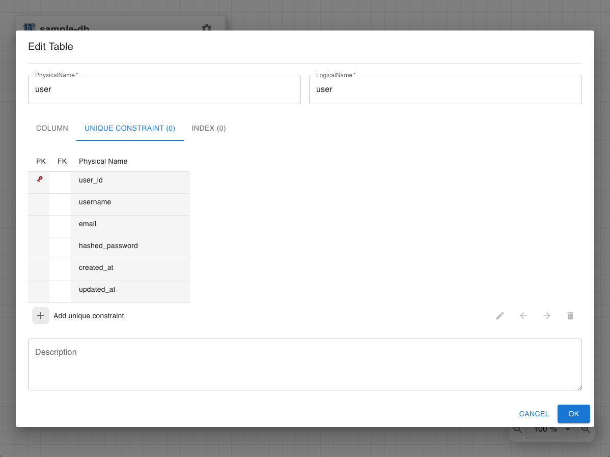
Select UNIQUE CONSTRAINT Tab: Click the "UNIQUE CONSTRAINT" tab in the dialog
-
Add New Constraint: Click the "Add Unique Constraint" button
-
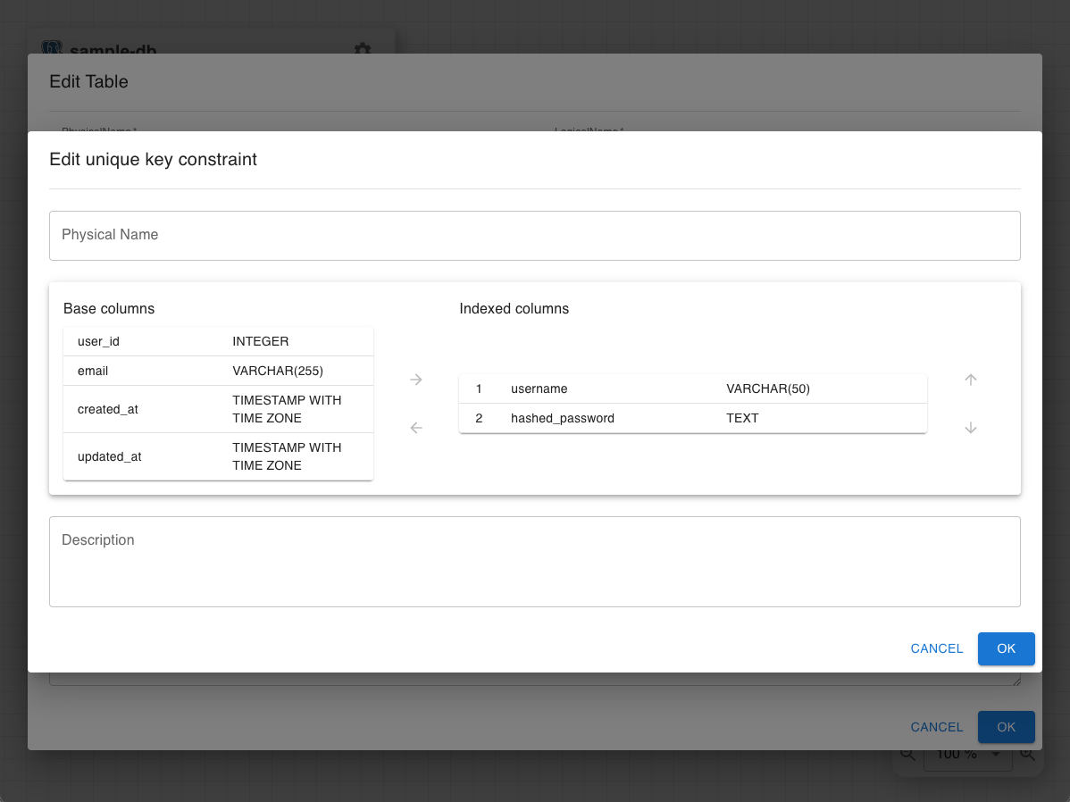
Configure Constraint:
- Constraint Name: Enter constraint name (e.g., uq_user_product, uq_room_datetime)
-
Select Columns: Select columns to include in the constraint
- Select target columns from the left list
- Create composite unique constraint by selecting multiple columns
- Column Order: Adjust the order of selected columns
-
Save Constraint: Click the "OK" button to save the constraint
Design Considerations
Constraint Name Naming Convention
-
Use Prefix: Recommend naming convention starting with
uq_(e.g., uq_email, uq_username_email) - Include Column Names: Reflect column names included in the constraint in the name
- Ensure Uniqueness: Ensure constraint names don't duplicate within the table
Composite Unique Constraint Design Principles
- Minimum Columns: Compose with minimum columns necessary to ensure uniqueness
- Handling NULL Values: Note that behavior differs by database when columns contain NULL values
- Automatic Index Creation: In many DBMS, indexes are automatically created for unique constraints
Practical Examples
Example 1: Prevent Duplicate Favorite Registration
Table name: user_favorites
Composite unique constraint: uq_user_product
Target columns: user_id + product_id
Purpose: Prevent the same user from adding the same product to favorites multiple times
Example 2: Prevent Period Overlap
Table name: room_reservations
Composite unique constraint: uq_room_datetime
Target columns: room_id + start_datetime
Purpose: Prevent multiple reservations in the same time period for the same room
Example 3: Composite Natural Key
Table name: product_prices
Composite unique constraint: uq_product_date
Target columns: product_id + effective_date
Purpose: Prevent multiple price records for the same product on the same effective date
Editing and Deleting Composite Unique Constraints
How to Edit
- Open UNIQUE CONSTRAINT tab
- Double-click the target constraint or click the edit button
- Add/remove columns or change order
- Save with "OK"
How to Delete
- Open UNIQUE CONSTRAINT tab
- Select the target constraint
- Click the delete button or press Delete key
Warning
Deleting a composite unique constraint removes the data uniqueness guaranteed by that constraint. Thoroughly confirm the impact scope before deletion.
In database performance optimization, indexes are extremely important elements. Proper index design can dramatically improve search performance.
Detailed Index Creation Process
Basic Index Creation Procedure
- Display Table Edit Dialog: Open the table edit screen for the target column
- Select Index Tab: Click the "INDEX" tab in the dialog
- Add New Index: Create a new index with the "Add Index" button
-
Detail Index Settings:
- Index Name: Set an easily identifiable name (e.g., idx_user_email, idx_order_date)
- Index Type: Select type according to usage
- Column Order: Set column order for composite indexes
Composite Index Design Principles
Importance of Column Order
- High Selectivity Columns First: Place columns that can filter more rows first
- Consider Search Frequency: Place frequently searched columns forward
- Utilize Leftmost Prefix Match: Enable index use with columns consecutive from the beginning
Index Performance Optimization
Utilizing Covering Indexes
- Concept: Include all columns needed for search in the index
- Benefit: Completely avoid table access for dramatic performance improvement
- Design Example: Index together column groups frequently used in SELECT statements
Index Maintenance Considerations
Impact on Update Performance
- Tradeoff: INSERT/UPDATE/DELETE performance decreases in exchange for search performance improvement
- Appropriate Balance: Index design considering application's read/write ratio
- Regular Review: Index adjustment according to application usage pattern changes
Impact on Storage Capacity
- Capacity Calculation: Index size estimation and capacity planning
- Eliminate Duplicate Indexes: Consolidate similar indexes
- Regular Maintenance: Index defragmentation resolution and optimization
Column Model is a feature that centrally manages column definition information (physical name, logical name, data type, precision, description, etc.). In ERD Designer, when you create a column, it's automatically registered as a column model and the same column definition can be reused across multiple tables.
Benefits of Column Model
- Design Consistency: Uniformly define columns with the same meaning (e.g., user_id) across multiple tables
- Improved Work Efficiency: Reduce input work by reusing once-defined columns
- Batch Updates: When you update a column model, changes are reflected in all tables using it
- Maintainability: When data type changes are needed, apply across the board with a single modification
When you create a new column, its definition is automatically registered as a column model.
Information Automatically Registered
- Physical Name
- Logical Name
- Column Type and its attributes (precision, scale, unsigned, etc.)
- Description
Registration Timing
- When you click "OK" in the column edit dialog
- When you change column definition (existing column model is updated)
Note
Constraint conditions such as Primary Key, NOT NULL, UNIQUE, Auto Increment, Default Value are not included in the column model. These are managed individually for each table.
You can search for already defined column models and apply them to new columns.
Basic Reuse Procedure
- Start Column Addition: Click "Add Column" in the table edit dialog
- Display Search Dialog: Click the search icon (🔍) to the right of "Create new column model."
-
Search Column Model: The Search column model dialog is displayed
- Physical Name: Filter by physical name
- Logical Name: Filter by logical name
- Type: Filter by data type
- Description: Filter by description text
- Select Model: Click to select the column model you want to reuse
- Apply: Click the "OK" button or double-click the column model
Filtering Function
In the search dialog, you can filter results in real-time by entering text in each field. You can also combine multiple conditions.
Checking Column Model Association Status
When you open the column edit dialog, the current column model association status is displayed:
- New Column Model: Displays "Create new column model."
- Associated with Existing Model: Displays "Associated with column model ''"
Switching to Another Column Model
- Click the search icon in the column edit dialog
- Select the column model you want to newly associate
- Existing association is replaced with the new model
Unlinking Column Model Association
Unlinking the association creates that column as an independent new column model.
- In the column edit dialog, click the "×" icon to the right of the column model name
- A confirmation dialog is displayed, so click "UNLINK"
- Association is unlinked and returns to "Create new column model." state
Important
Unlinking a column model association retains information such as column data type and name. It's just treated as a new independent column model.
When you update a column model, changes are automatically reflected in all columns referencing that model.
Batch Update Procedure
- Edit Target Column: Edit the column you want to update in any table
- Change Column Definition: Change data type, precision, logical name, description, etc.
- Save: Click the "OK" button
- Automatic Reflection: Changes are reflected in all other columns using the same column model
Items Subject to Batch Update
- Physical Name
- Logical Name
- Column Type
- Precision and Scale
- Unsigned attribute
- Array attribute
- Description
Items Not Subject to Batch Update
- Primary Key
- NOT NULL
- UNIQUE
- Auto Increment
- Default Value
Warning
Data type changes may affect existing relationships. When changing data types of columns referenced by foreign keys, be careful to maintain referential integrity.
When reusing a column model, you can override physical names and logical names for individual tables.
Override Method
-
Open the column edit dialog with a column model associated
-
Enter a new name in the Physical Name or Logical Name field
-
Click "OK" to save

Override Behavior
- The entered name is used as the column name for that table
- The column model itself is not changed
- No impact if the same column model is used in other tables
- If the field is empty, the column model's name is used
Usage Example
When you're using a column model called user_id in a table but want to use the name author_id in a specific table.
Columns with foreign key constraints must have the same data type as the referenced column.
Constraints When Setting Foreign Keys
- Data Type Fixed: Columns used in relationships cannot change data type
- Column Model Change Restriction: When changing association of foreign key columns, only column models with data types compatible with the referenced column can be selected
- Type Match: Precision, scale, unsigned attributes must also match
Automatic Processing When Creating Relations
When creating a relationship, if adding a new column to the child table:
- Parent table's column model is automatically referenced
- Data type, precision, etc. become the same as parent column
- Primary Key, NOT NULL, UNIQUE are not inherited (individual setting required)
Column models are automatically deleted when the following conditions are met:
Automatic Deletion Conditions
- Not referenced by any table's columns
- User intentionally unlinked all references
Deletion Timing
- When deleting a table
- When deleting a column
- When unlinking a column model association and switching to another model
Note
Column model deletion is done automatically, so manual deletion operations are unnecessary. Unused column models do not accumulate.
Example 1: Unifying Common ID Columns
Uniformly manage user_id used across multiple tables:
- Create
user_idasINTEGERtype inusertable - Reuse the same
user_idas foreign key inposttable - Reuse the same
user_idincommenttable - Later changing
user_idtoBIGINTreflects in all tables
Example 2: Reusing Timestamp Columns
Unify common columns like created_at and updated_at:
- Create
created_atcolumn asTIMESTAMPtype - Reuse the same column model in all tables
- If date-time format changes are needed, apply across the board with one modification
Example 3: Unifying Amount Columns
Unify amount-representing columns with DECIMAL(10, 2):
- Create
pricecolumn asDECIMAL(10, 2) - Reuse for all amount columns such as product price, order amount, payment amount
- If precision changes are needed, can change in bulk
Column Group is a feature that allows defining multiple columns together as one group and adding them to tables in bulk. You can efficiently manage standard column sets that are used repeatedly.
Benefits of Column Group
- Improved Work Efficiency: Add frequently used column sets at once, greatly reducing input work
- Ensure Consistency: Use the same column set uniformly across multiple tables
- Maintainability: When you update a group definition, it's reflected in all tables using it
- Design Standardization: Standardize common column sets (audit columns, address information, etc.) within teams
Difference from Column Model
-
Column Model: Manages individual column definitions (e.g.,
user_id,created_at) -
Column Group: Manages multiple columns as a set (e.g., Address Information Group =
postal_code+prefecture+city+address)
Note
Columns included in Column Groups are managed as independent column models. Groups are just a feature to express "collections" of columns.
This section explains the procedure for creating new Column Groups.
Creation Procedure
-
Open Column Group Management Screen: Click the settings button (⚙️) in the title panel and select "Column Group"
-
Add New Group: Click the "Add" button in the displayed dialog
-
Enter Group Name:
- GroupName: Enter group name (e.g., Address Information, Audit Columns, Price Information)
- Description: Document group description and purpose (optional)
-
Add Columns: Click the "Add column" button to add columns to include in the group
- When creating new column: Define details in column edit dialog
- When reusing existing column model: Select column model from search icon
-
Adjust Column Order: Adjust column display order by drag & drop or arrow buttons
-
Save Group: Click the "OK" button to save the Column Group
Creation Example: Audit Columns Group
GroupName: Audit Columns
Description: Column set for managing record creation and update information

Column composition:
- created_at (TIMESTAMP): Record creation date/time
- created_by (INTEGER): Creator ID
- updated_at (TIMESTAMP): Last update date/time
- updated_by (INTEGER): Updater ID
This section explains how to edit or delete existing Column Groups.
Editing Column Groups
-
Open Column Group Management Screen: Select "Column Group" from settings button (⚙️)
-
Select Group: Click the group you want to edit from the left list
-
Start Editing:
- Double-click the group, or
- Select the group and click the "Edit" button
-
Edit Content:
- Change group name or description
- Add, delete, reorder columns
- Change individual column definitions
-
Save Changes: Click the "OK" button
Precautions When Editing
- Changing column models included in a group affects all tables using that column model
Deleting Column Groups
-
Open Column Group Management Screen: Settings button (⚙️) → Select "Column Group"
-
Select Group: Click the group you want to delete
-
Execute Deletion: Click the "Delete" button
-
Confirm: Confirm deletion in the confirmation dialog
Important
When you delete a Column Group, the corresponding definitions are deleted from tables that used it.
This section explains how to add created Column Groups to tables.
Addition Procedure
-
Open Table Edit Dialog: Double-click the target table
-
Click Column Group Add Button: Click the "Add group column" button (icon: ≡+) at the bottom of the column list
-
Select Column Group:
- Column Group management dialog is displayed
- Select the group you want to add from the left list
- Column list within the group is displayed on the right
-
Confirm Group: Click the "OK" button
-
Reflect in Table: All columns within the selected Column Group are added to the table in bulk
Operations After Addition
- Adjust Column Order: Added column groups can be reordered by drag & drop like other columns
- Set Constraints: Primary Key, NOT NULL, UNIQUE, etc. from the column group definition are reflected
Example 1: Address Information Group
Uniformly manage address information across multiple tables such as customer table, shipping address table, store table:
GroupName: Address Information
Column composition:
- postal_code (VARCHAR(7)): Postal code
- prefecture (VARCHAR(50)): Prefecture
- city (VARCHAR(100)): City/Town/Village
- address (VARCHAR(200)): Street address/Building name
Example 2: Audit Columns Group
Record creation and update information in all tables:
GroupName: Audit Columns
Column composition:
- created_at (TIMESTAMP, NOT NULL, DEFAULT CURRENT_TIMESTAMP): Creation date/time
- created_by (INTEGER): Creator ID
- updated_at (TIMESTAMP): Update date/time
- updated_by (INTEGER): Updater ID
Example 3: Price Information Group
Unify price-related information for products, services, pricing plans:
GroupName: Price Information
Column composition:
- price (DECIMAL(10, 2), NOT NULL): Price
- tax_rate (DECIMAL(5, 2), DEFAULT 0.10): Tax rate
- currency_code (VARCHAR(3), DEFAULT 'JPY'): Currency code
Example 4: Period Management Group
Manage validity periods for campaigns, contracts, reservations:
GroupName: Period Management
Column composition:
- start_date (DATE, NOT NULL): Start date
- end_date (DATE): End date
- is_active (BOOLEAN, DEFAULT true): Active flag
Benefits of Usage
- When Creating New Tables: Add necessary column sets in bulk by just selecting a group
- Design Standardization: Share common column set definitions across the entire team
- Prevent Input Errors: Reduce typos and definition mistakes from repeated input
- Future Extensions: When adding items to standard column sets, just update the group definition
In database design, relationships between tables form the foundation for information integrity and efficient data management. ERD Designer allows you to accurately represent and manage various types of relationships.
Detailed Basic Relationship Patterns
1:1 (One-to-One) Relationship
-
Characteristics: One record in parent table relates to at most one record in child table
-
Implementation Method: Add UNIQUE constraint to foreign key in child table
-
Usage Examples:
- User table ↔ User profile table
- Product table ↔ Product details table
- Employee table ↔ Employee personal information table
-
Design Considerations:
- Consider whether separation is truly necessary (validity of normalization)
- Separation by access frequency difference (frequently accessed basic information vs. rarely accessed detailed information)
- Separation by security requirements (general information vs. confidential information)
1:N (One-to-Many) Relationship
- Characteristics: One record in parent table relates to multiple records in child table
- Implementation Method: Add parent table's primary key as foreign key to child table
- Most Common Pattern: Occupies most of database design
-
Usage Examples:
- Customer table ← Order table (one customer has multiple orders)
- Category table ← Product table (one category has multiple products)
- Department table ← Employee table (one department has multiple employees)
N:M (Many-to-Many) Relationship
- Characteristics: Records in both tables relate to multiple records mutually
- Implementation Method: Use intermediate table (junction table) to decompose into two 1:N relationships
-
Usage Examples:
- Student table ↔ Class table (students take multiple classes, classes have multiple students)
- Product table ↔ Tag table (products have multiple tags, tags apply to multiple products)
- User table ↔ Role table (users have multiple roles, roles are assigned to multiple users)
Intermediate Table Design Principles
- Naming Convention: Combine two related table names (e.g., student_courses, product_tags)
- Primary Key Design: Composite primary key of two related foreign keys, or independent surrogate key
- Additional Attributes: Attributes of the relationship itself (e.g., registration date/time, expiration date)
Using the Memo feature, you can place free text notes on ER diagrams. This is useful for recording design annotations, future expansion plans, important constraints, etc.
Basic Memo Creation Procedure
- Select MEMO Mode: Select "MEMO" from the edit mode panel on the left side of the screen
- Decide Placement Position: Click on the canvas where you want to place the memo
- Enter Text: Enter memo content in the displayed dialog
- Confirm Creation: Click the "OK" button to create the memo
Editing and Deleting Memos
- Edit: Double-click a memo to edit it directly. After editing, click outside the memo to save
- Move: Drag and move memos in SELECT mode
- Delete: Select memo and click delete icon, or press Delete or Backspace key
By customizing memo appearance, you can organize visually according to purpose.
Configurable Items
- Text Content: Text to display in memo (multi-line supported)
- Font Size: Adjust text size
- Color: Change memo background color
- Size: Adjust width and height of memo box
By controlling memo foreground/background relationship (Z-order), you can use them for different purposes.
Foreground Mode
- Placement: Memo is displayed in front, overlapping on top of tables and relation lines
-
Usage:
- Displaying important notes and alerts
- Comments on specific tables or relations
- Explicitly showing TODOs and issues
Background Mode
- Placement: Memo is displayed in back, placed under tables and relation lines
-
Usage:
- Grouping related table groups (area division)
- Section headings and classifications
- Visual organization by functional module
Schema is a namespace for logically grouping tables and other objects (views, functions, etc.) within a database.
Main Uses of Schema
- Functional Separation: Separate schemas by function such as user management, product management, order management
- Environmental Management: Separate development, test, production environments within the same database
- Permission Management: Control access permissions on a per-schema basis
- Avoid Name Collisions: Same table names can be used within different schemas
Supported Databases
-
PostgreSQL: Full schema support (default is
publicschema) -
MS SQL Server: Full schema support (default is
dboschema) - MySQL: Treats schema and database as synonymous, so unsupported in ERD Designer
ERD Designer makes Schema management easy.
How to Create Schema
- Access Settings Screen: Click the settings button (⚙️) and click "DB Schema" from the displayed menu.
- Add New Schema: Click the "Add Schema" button and enter the schema name
- Save: Click the "OK" button to create the Schema
Editing Schema
To change the name of a created Schema, select the target Schema from the Schema list and click the edit icon.
Deleting Schema
To delete an unused Schema, select the target Schema from the Schema list and click the delete icon.
Important
Deleting a Schema does not delete tables assigned to that Schema. Only the table's Schema setting becomes empty.
Setting Default Schema
Setting a default Schema in the Schema list causes tables without schema settings to have the default Schema output as their schema definition during DDL export.
By assigning created Schemas to tables, logical grouping becomes possible.
Assignment Procedure
- Open Table Edit Dialog: Double-click the target table
- Set Schema Field: In the table properties "Schema" field, select the schema you want to assign
- Save: Click the "OK" button to save changes
Confirming Schema Assignment
- When displaying table names, schema names may be included (e.g.,
user_management.users) - When exporting DDL with Schemas option enabled, schema names are included in DDL
When exporting DDL from tables with Schema set, enabling the Schemas option generates DDL including schema names.
For PostgreSQL
CREATE SCHEMA IF NOT EXISTS user_management;

CREATE TABLE user_management.users (
    user_id INT PRIMARY KEY,
    username VARCHAR(50) NOT NULL,
    ...
);
For MS SQL Server
CREATE SCHEMA user_management;

CREATE TABLE user_management.users (
    user_id INT PRIMARY KEY,
    username VARCHAR(50) NOT NULL,
    ...
);
Tip
Using schemas can maintain an organized state even in large-scale databases, greatly improving manageability.
Perspective is a feature that logically groups tables and memos in ER diagrams by function, purpose, etc., and allows switching displays. In large-scale ER diagrams, it improves work efficiency by displaying only necessary information.
Benefits of Perspective
- Information Organization: Display large-scale ER diagrams classified by function or module
- Improved Work Efficiency: Display only the currently working part to improve screen clarity
- Phase Management: Switch necessary table sets for each development phase
- Presentation: Display only the parts you want to explain for clear presentation
- Multiple View Management: Create multiple viewpoints from the same ER diagram and switch flexibly
Usage Scenarios
- Functional Views: Display by function such as user management, product management, order management
- Phase Views: Display by development stage such as Phase 1, Phase 2
- Assignee Views: Display each team member's area of responsibility
- Layer Views: Display by data characteristics such as master data, transaction data
Note
Perspective is a display switching feature handled by ERD Designer and does not affect table or relationship definitions themselves.
This section explains the procedure for creating new Perspectives.
Creation Procedure
-
Open Perspective Management Screen: Click the settings button (⚙️) in the title panel and select "Perspective"
-
Add New Perspective: Click the "Add perspective" button (+ icon)
-
Enter Perspective Information:
- Name: Enter Perspective name (e.g., User Management, Product Management, Phase 1)
- Description: Document Perspective description and purpose (optional)
-
Select Tables and Memos:
- Left column lists all tables and memos in the ER diagram
- Click checkboxes in each Perspective column to select elements to include
- One table can be included in multiple Perspectives
-
Save Perspective: Click the "OK" button to save
Creation Example
Name: User Management
Description: Tables related to user authentication and permission management

Included tables:
- users
- roles
- permissions
- user_roles (User role relations)
This section explains how to edit or delete existing Perspectives.
Editing Perspectives
-
Open Perspective Management Screen: Settings button (⚙️) → Select "Perspective"
-
Select Perspective: Click the column of the Perspective you want to edit to select it
-
Start Editing: Click the "Edit perspective" button (pencil icon)
-
Edit Content:
- Change Perspective name or description
- Change checks for included tables and memos
-
Save Changes: Click the "OK" button
Reordering Perspectives
- Drag and drop Perspective columns to change display order
- Or adjust order with arrow buttons (← →)
Deleting Perspectives
-
Open Perspective Management Screen: Settings button (⚙️) → Select "Perspective"
-
Select Perspective: Click the Perspective you want to delete
-
Execute Deletion: Click the "Remove" button (trash icon)
Important
Deleting a Perspective does not delete tables or memos in the ER diagram. Only the display settings are deleted.
This section explains how to switch ER diagram display using created Perspectives.
How to Switch Display
A list of Perspectives is displayed in the left panel.
-
Select Perspective: Select the Perspective name you want to display from the list in the left panel
-
Reflect on Screen: Only tables and memos included in the selected Perspective are displayed on the canvas
Return to Show All
- Selecting "(Default)" in the list displays all tables and memos
Show half-bounded line Option
The Perspective display switching panel has a "Show half-bounded line" checkbox.
- When enabled: Relation lines between tables included in Perspective and tables not included (lines only half included) are also displayed
- When disabled: Only relation lines between tables included in Perspective are displayed
- Purpose: Useful to enable when you want to confirm relationships with other functions
Confirmation in Perspective Management Screen
Settings button (⚙️) → Selecting "Perspective" opens the Perspective management screen. Here you can compare multiple Perspectives side by side:
Table/Memo       | User Management | Product Management | Order Management
----------------|-----------------|-------------------|------------------
users           |        ✓        |                   |        ✓
products        |                 |         ✓         |        ✓
orders          |                 |                   |        ✓
...
Example 1: Functional Perspectives
Divide large-scale system by functional module:
Perspective 1: User Management
- users, roles, permissions, user_roles

Perspective 2: Product Management
- products, categories, product_images, inventory

Perspective 3: Order Management
- orders, order_items, payments, shipments
Example 2: Development Phase Perspectives
Switch display according to staged development plan:
Perspective 1: Phase 1 (MVP)
- Only tables needed for minimum functionality
- users, products, orders

Perspective 2: Phase 2 (Extended Features)
- Phase 1 + additional feature tables
- users, products, orders, reviews, wishlists

Perspective 3: Phase 3 (Complete Version)
- Includes all tables
Example 3: Data Type Perspectives
Classify by data nature:
Perspective 1: Master Data
- categories, brands, users, stores

Perspective 2: Transaction Data
- orders, order_items, payments, shipments

Perspective 3: Analytics Data
- sales_summary, user_analytics, product_metrics
Example 4: Team Assignment Perspectives
Display by development team's area of responsibility:
Perspective 1: Frontend Team
- Only tables directly related to UI

Perspective 2: Backend Team
- All tables used in API

Perspective 3: Data Team
- Analysis and report-related tables
Example 5: Review and Presentation
Focused display for specific explanations and reviews:
Perspective: User Flow Explanation
- Display only tables related to flow from user registration to purchase
- users, authentication, cart, orders, payments
Benefits of Usage
- Improved Visibility: Display only necessary information to improve screen clarity
- Work Efficiency: Maintain concentration by hiding elements unrelated to current work
- Communication: Present clearly when explaining to team members or stakeholders
- Staged Development: Clearly visualize implementation scope for each phase
- Documentation: Export functional ER diagram images to include in design documents
Export features allow you to output DDL, ER diagram images, and table specification documents.
Detailed Option Explanations
- Tables: Generate CREATE TABLE statements. Usually always enable
- Indexes: Generate CREATE INDEX statements. Recommended for performance optimization
- Foreign Keys: Generate ALTER TABLE statements for foreign key constraints. Recommended for ensuring referential integrity
- Comments: Generate COMMENT statements. Useful for database-level documentation
- Schemas: Generate DDL including schema names (PostgreSQL, MS SQL Server only)
You can save ER diagrams as PNG format image files.
Usage
- Embedding in documents (Word, Markdown, etc.)
- Sharing in design reviews
- Uploading to project management tools
Table specification documents are documents that summarize design content in tabular format.
Output Format
-
For Online Tool: Excel file (
.xlsx) - For Google Drive App: Google Spreadsheet
Contents
- Table list (table name, logical name, description)
- Column definitions (column name, logical name, data type, constraints, description)
- Index list
- Foreign key constraint list
Save files in ERD Designer's native format (.erd).
Important
ERD file export is only supported in the online tool.
When using Google Drive App, use .erd files saved on Google Drive.
Usage
- Regular backups
- Migration to another environment (another browser, another machine)
- Management with version control systems (Git, etc.)
- File sharing with team members
You can load previously exported .erd files to restore ER diagrams.
Important
ERD file import is only supported in the online tool.
Procedure
- On the online tool top screen, select "IMPORT FROM ERD FILE".
- Select the saved
.erdfile. - The ER diagram is restored and you can continue editing.
Usage
- Restoring from backup
- Project migration from another environment
- Loading files received from team members
This feature imports DDL generated from existing databases to automatically create ER diagrams.
Feature Overview
This feature is useful in the following situations:
- Visualizing and documenting existing databases
- Reverse engineering legacy systems
- Migrating from DDL created with other tools
- Analyzing database structure
Basic Usage
- Click the settings button (⚙️) and select "Import from DDL" from the displayed menu
- Enter DDL text
- Set "Comment Separator" if necessary
- Click the "CHECK DDL" button to parse DDL
- If parsing is successful without issues, click the "IMPORT" button
Comment Separator Feature
If column comments include logical names and descriptions, you can automatically separate them by specifying a separator.
Example:
COMMENT ON COLUMN users.username IS 'Username | Unique identifier used during login';In this case, specifying | as Comment Separator:
- Logical name:
Username - Description:
Unique identifier used during login
are automatically separated.
Limitations
Warning
The DDL import feature is experimental and has the following limitations:
- Does not support complex DDL syntax (views, triggers, stored procedures, etc.)
- Some advanced data types and constraints may not be parsed correctly
- Does not support special features like partition definitions, inheritance
- May not support DDL dialects and proprietary extensions
Troubleshooting
If Import Fails
- Confirm that DDL conforms to standard syntax of the supported database
- Try again after removing unnecessary statements (USE, SET, etc.)
- Check error messages to identify problematic parts
If Some Tables Are Not Generated
- Confirm that CREATE TABLE statements have correct syntax
- Tables without column definitions are not generated
If Foreign Keys Are Not Set Correctly
- When adding foreign keys with ALTER TABLE statements, confirm that referenced tables are defined first
- Confirm that foreign key constraint syntax is correct