Qc render fix #3186
Qc render fix #3186
Conversation
 balopat
left a comment
balopat
left a comment
There was a problem hiding this comment.
Thank you for working on this!
I will have to look at the algo itself, but first it needs a test - I recommend reproducing the issue with the smallest possible example with a test that would fail without your fix. Then add in your fix. That should also remove the need for ignoring the coverage tool!
| if row_has_item: | ||
| diagram2.write(2 * w - 1, y, r'&\qw\\') | ||
| else: | ||
| diagram2.write(2 * w - 1, y, r'& \\') # coverage: ignore |
There was a problem hiding this comment.
We should only ignore coverage in very exceptional scenarios where it's impossible/very expensive to test. I don't think this is that case.
There was a problem hiding this comment.
Thanks for the help! Sorry about the mistake here, I did not understand what the coverage tool was for fully. I suppose I would add the appropriate test into qcircuit_test.py? On a side note, I had some problems with not passing the formatting test. Is there a formatting tool everyone else is using for this project? I ran mypy and pylint with the appropriate configuration file. Neither of them complained about my coding style. Yet the formatting test gave me a hard time.
There was a problem hiding this comment.
Yes, you should write a new test method in qcircuit_test.py. It will contain a test circuit and the expected output similar to this:
Cirq/cirq/contrib/qcircuit/qcircuit_test.py
Lines 110 to 123 in d848611
Regarding formatting - you can just run check/format-incremental --apply and that will reformat your files properly.
There was a problem hiding this comment.
btw feel free to jump on https://gitter.im/cirqdev/community if you want to chat
There was a problem hiding this comment.
Thanks a lot for the help! 👍 I ended up using yapf directly. The ./format-incremental --apply did not really work for me. Perhaps it would be nice for me to mention that by the end of CONTRIBUTING.md? I felt really bad spamming these commits that fail the format testing. Perhaps it would help future newbie's like me who wants to contribute?
balopat
left a comment
There was a problem hiding this comment.
Thanks for the test! I added my comments, I think an alternative design can make this significantly simpler: we should just skip moment group generation for qcircuit. Unless there is a way to draw those brackets with qcircuit - which would be even cooler.
| expected_diagram = r""" | ||
| \Qcircuit @R=1em @C=0.75em { | ||
| \\ | ||
| & & & & & & \\ |
There was a problem hiding this comment.
we shouldn't need to have an empty line here
| &\lstick{\text{1}}& \qw& \qw& \qw\qwx&\control \qw & \qw&\qw\\ | ||
| &\lstick{\text{2}}& \qw& \qw&\targ \qw\qwx& \qw\qwx& \qw&\qw\\ | ||
| &\lstick{\text{3}}& \qw& \qw& \qw &\targ \qw\qwx& \qw&\qw\\ | ||
| & & & & & & \\ |
There was a problem hiding this comment.
we shouldn't need to have an empty line here either
| # if has none wire before, should draw wire | ||
| post1 = r'\qw' if key in qw and row_has_item else '' | ||
| post2 = '' | ||
| if key in qwx: |
There was a problem hiding this comment.
This solution is interesting, but it is very hard to read and reason about.
The key issue is that the moment groups character is not handled well by qcircuit. So, I would rather introduce a by default True parameter to to_text_diagram_drawer, something like draw_moment_groups - and then the qcircuit drawer could set that to false.
There was a problem hiding this comment.
Got it! I will get back to this ASAP but I just lost power here a couole hours ago. The storm hit us hard. Just a heads up that I might not be able to work at all in the next day or two
There was a problem hiding this comment.
No worries, no rush - good luck with the storm, stay safe!
There was a problem hiding this comment.
Hello @balopat, as I looked at your suggestion, I realized how silly my method is. I tried to keep the angle bracket to indicate the moment as I thought it is a really good reminder for viewers that these gates can be run simultaneously. But I hit a wall and got no good results. So, I basically did what you said, and added a test in qcircuit_test.py to account for the circuit that caused our initial problem #3183.
I have been trying to battle with the doc build error from CI but I did not even change the file it was mentioning. Then I went to change the file itself by just calling yapf on the mentioned code, it is still giving me an error. If you got time, could you please take a look at it? Thanks in advance for your time and help.
|
Hi @exAClior - I suggest fixing somehow your branch - you seemed to pull in some commits from master incorrectly - the 3 files that you changed look good, but Github shows 26 files changed somehow. The doc failures are unrelated, other PRs are breaking on it too - I'll fix them soon. |
### Related Issue Fixes quantumlib#3183. ### Source of Error In the original code, we added \qw and \qwx too aggressively. Whenever there is a line in the original diagram, we will try to insert \qw or \qwx accordingly. This causes the program to try to add the angle bracket thing above and below the two cnots mentioned in the issue to be recognized as wires. ### Summary of Fix Add the pruning process for adding \qw and \qwx. Need none wire item to be on the same row or previous row needs to be connected to the current one. ### Output After Fix Rerunning code outputs the following. \Qcircuit @r=1em @C=0.75em { \\ & & & & & & \\ &\lstick{\text{0}}& \qw& \qw&\control \qw & \qw & \qw&\qw\\ &\lstick{\text{1}}& \qw& \qw& \qw\qwx&\control \qw & \qw&\qw\\ &\lstick{\text{2}}& \qw& \qw&\targ \qw\qwx& \qw\qwx& \qw&\qw\\ &\lstick{\text{3}}& \qw& \qw& \qw &\targ \qw\qwx& \qw&\qw\\ & & & & & & \\ \\ } ### Latex Compiled Output Following are the Latex compiled output for the above code and one extra to show we don't over connect using \qwx 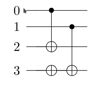 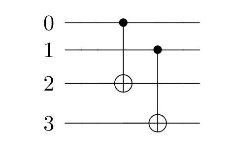 ### Misc Seems to pass the qcircuit_test.py. But I fear that we might need other tests in the future? Please let me know if I did something wrong.
Related Issue
Fixes #3183.
Source of Error
In the original code, we added \qw and \qwx too aggressively. Whenever there is a line in the original diagram, we will try to insert \qw or \qwx accordingly. This causes the program to try to add the angle bracket thing above and below the two cnots mentioned in the issue to be recognized as wires.
Summary of Fix
Add the pruning process for adding \qw and \qwx. Need none wire item to be on the same row or previous row needs to be connected to the current one.
Output After Fix
Rerunning code outputs the following.
Latex Compiled Output
Following are the Latex compiled output for the above code and one extra to show we don't over connect using \qwx


Misc
Seems to pass the qcircuit_test.py. But I fear that we might need other tests in the future? Please let me know if I did something wrong.