Repository navigation
Assembly Guide
| STL part | Qty | Repo link |
|---|---|---|
| Supported Ball Bearing | 24 | Supported Ball Bearing.stl |
| Omni Wheel Core | 2 | Omni Wheel Core.stl |
| Bearing Inner Ring | 4 | Bearing Inner Ring.stl |
| Ball Retainer | 4 | Ball Retainer.stl |
| Roller | 20 | Roller.stl |
| Omni Wheel Frame | 8 | Omni Wheel Frame.stl |
| Hub Retaining Ring | 4 | Hub Retaining Ring.stl |
| Rear Base | 1 | Rear Base.stl |
| Main Base Bolt | 4 | Main Base Bolt.stl |
| Rear Drive Bolt | 2 | Rear Drive Bolt.stl |
| Rear Deadwheel Bracket | 2 | Rear Deadwheel Bracket.stl |
| Rear Wheel Nut | 2 | Rear Wheel Nut.stl |
| Servo Coupler | 2 | Servo Coupler.stl |
| Servo Clamp | 2 | Servo Clamp.stl |
| Servo Bracket Left | 1 | Servo Bracket Left.stl |
| Servo Bracket Right | 1 | Servo Bracket Right.stl |
| Arm Base | 1 | Arm Base.stl |
| Wheel Bearing Bracket Left | 1 | Wheel Bearing Bracket Left.stl |
| Wheel Bearing Bracket Right | 1 | Wheel Bearing Bracket Right.stl |
| Front Axle Halve | 4 | Front Axle Halve.stl |
| Front Drive Bolt | 2 | Front Drive Bolt v2.stl |
| Arm Retainer Pin Halve | 8 | Arm Retainer Pin Halve.stl |
| Arm Pin Half Bracket | 4 | Arm Pin Half Bracket.stl |
| Arm Pin Mini Bracket | 4 | Arm Pin Mini Bracket.stl |
| Arm Pin Bolt | 4 | Arm Pin Bolt.stl |
| ESP32 Mount | 1 | ESP32 Mount.stl |
| ESP32 Bolt | 1 | ESP32 Bolt.stl |
| Bus Adapter Bracket | 1 | Bus Adapter Bracket.stl |
| Bus Adapter Clamping Foot | 2 | Bus Adapter Clamping Foot.stl |
| Bus Adapter Clamp Bolt | 1 | Bus Adapter Clamp Bolt.stl |
| Bus Adapter Bracket Top | 1 | Bus Adapter Bracket Top.stl |
| Bus Adapter Bracket Bottom | 1 | Bus Adapter Bracket Bottom.stl |
| Bus Adapter Bracket Retainer | 1 | Bus Adapter Bracket Retainer.stl |
| Bus Adapter Retainer Bolt | 1 | Bus Adapter Retainer Bolt.stl |
| Battery Lock | 1 | Battery Lock.stl |
Purchase the electronics in the sourcing table, then print the 3D parts from STL/ and follow the steps below.
| Part | Qty | Notes |
|---|---|---|
| Ball bearing | 12 | Supported Ball Bearing.stl |
| Omniwheel core | 2 | Omni Wheel Core.stl |
| Bearing inner ring | 2 | Bearing Inner Ring.stl |
| Ball retainer | 2 | Ball Retainer.stl |
Assembly
-
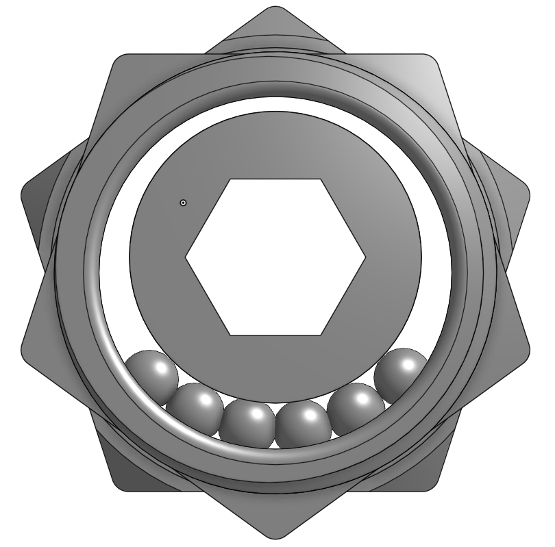
Insert all six ball bearings onto the omniwheel core, then slide in the bearing inner ring.
-
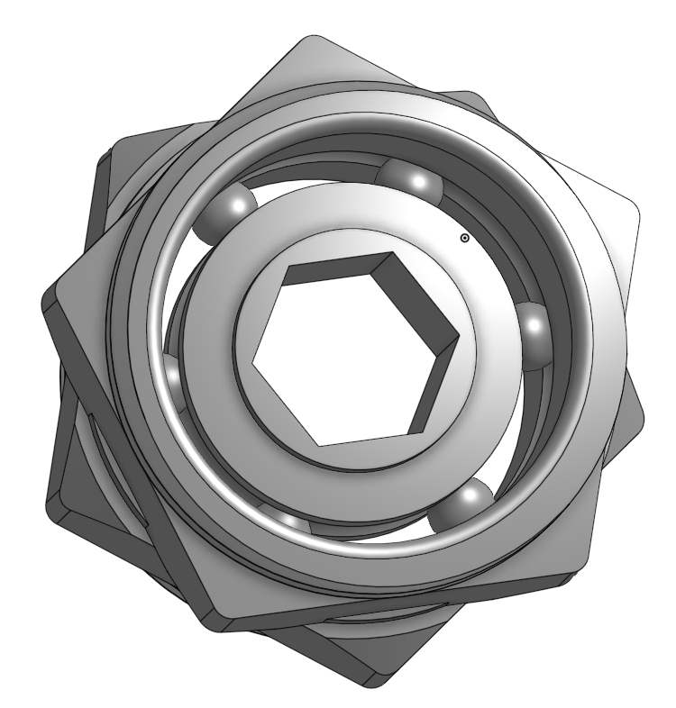
Push the bearing inner ring against the balls while turning it so that the protruding circle faces up. Align the balls so they are spaced evenly at 60°.
-
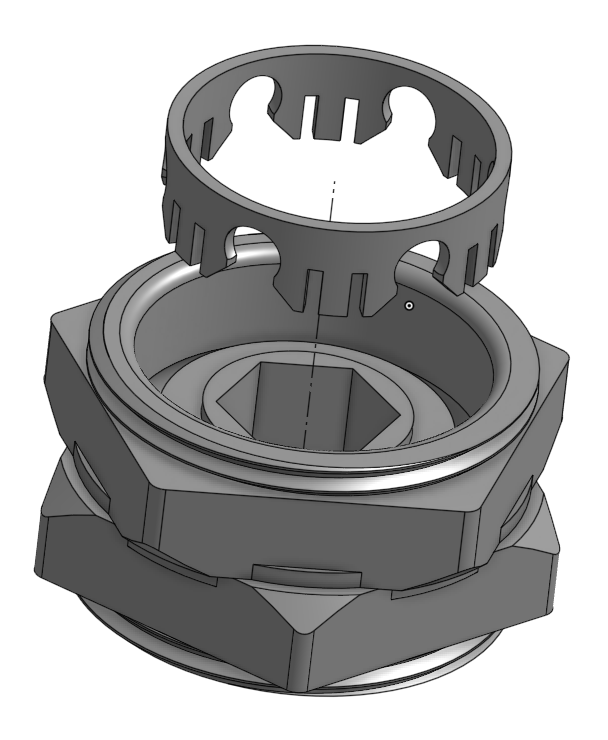
Push the ball retainer into the balls until it snaps into place.
-
Repeat for the other side.
| Part | Qty | Notes |
|---|---|---|
| Filament cut to 29 cm | 4 | Roller axle "shaft" |
| Roller | 20 | Roller.stl |
| Omniwheel frame side | 8 | Omni Wheel Frame.stl |
| Hub retaining ring | 4 | Hub Retaining Ring.stl |
Assembly
-
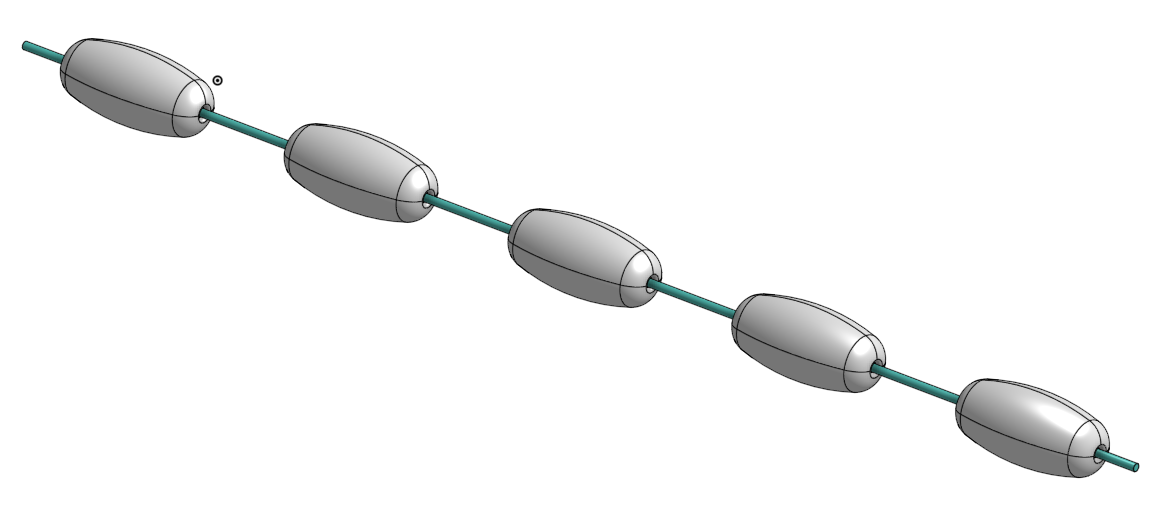
Slide five rollers onto a 29 cm filament, spacing them evenly.
-
Clamp the filament between two of the omniwheel frame sides.
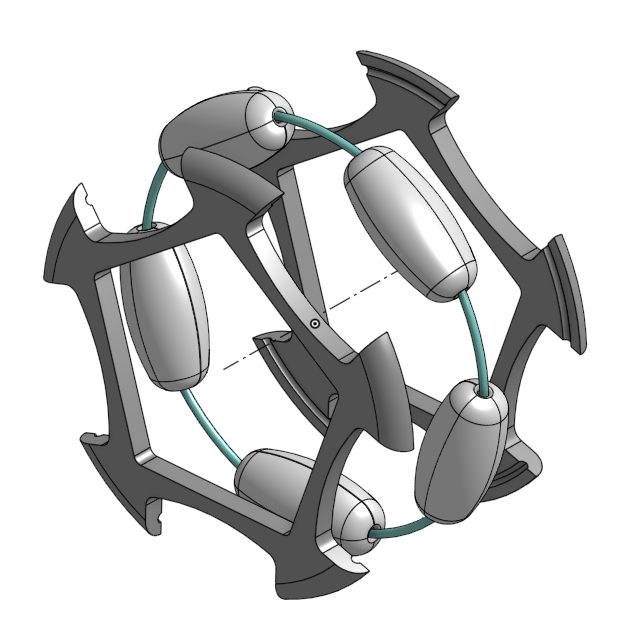
It may be helpful to place bits of CA (super glue) on each of the shafts so that the filament can stick to the omniwheel frame. You can also put a drop of CA right below the shaft so that the two frame halves stick together.
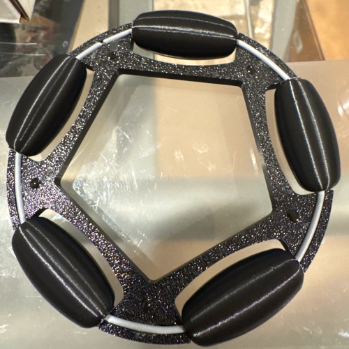
Image attributed to @kitchencamaro
-
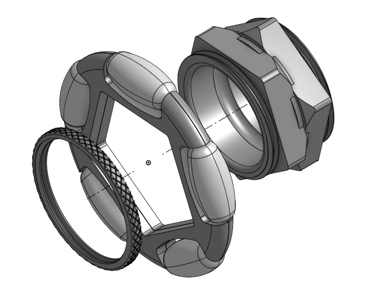
Place the clamped frame onto the omniwheel core and secure it with the hub retaining ring.
-
Repeat Steps 2.1–2.3 for the other side of the omniwheel.
-
Repeat for the other side of the robot.
| Part | Qty | Notes |
|---|---|---|
| Rear base | 1 | Rear Base.stl |
| Rear drive bolt | 2 | Rear Drive Bolt.stl |
| Rear deadwheel bracket | 2 | Rear Deadwheel Bracket.stl |
| Rear wheel nut | 2 | Rear Wheel Nut.stl |
| Omni wheel | 2 | From Steps 1–2 |
Assembly
-
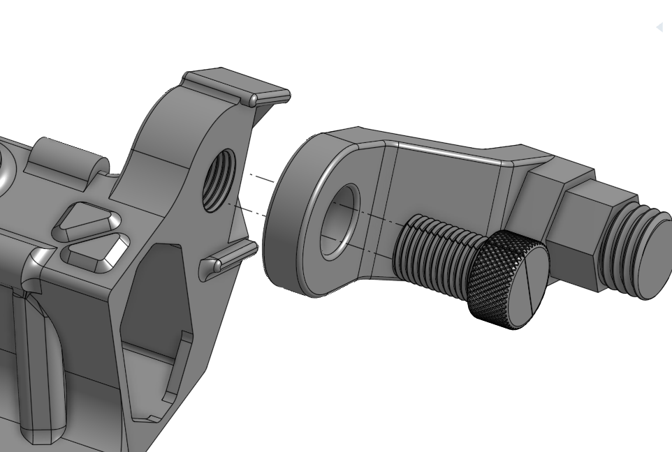
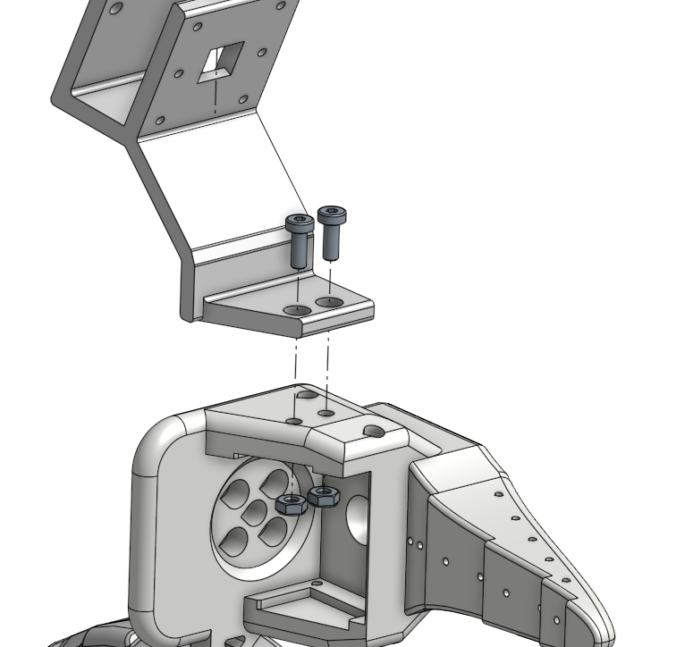
Connect the rear deadwheel bracket to the rear base with the rear drive bolt.
-
Slide the omni wheel onto the rear axle and tighten the rear wheel nut. Note that the pointy bits of the ball retainer should be facing outside, and the flat circular face of the ball retainer should be facing inside.
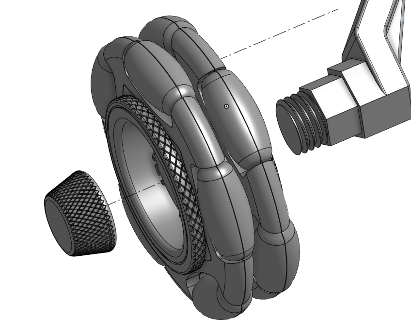
-
Repeat for the other side.
| Part | Qty | Notes |
|---|---|---|
| Feetech STS3215 servo (1/345) | 2 | From sourcing table |
| STS drive plate | 2 | |
| Phillips screw | 2 | |
| M3 × 5 mm screw | 8 | |
| Servo coupler | 2 | Servo Coupler.stl |
| Servo clamp | 2 | Servo Clamp.stl |
| Servo bracket | 1 each | Left · Right |
| Arm base | 1 | Arm Base.stl |
| Main base bolt | 2 | Main Base Bolt v2.stl |
Assembly
-
Attach the STS drive plate to the Feetech STS3215 servo with the Phillips screw, then use the four M3 × 5 mm screws to bolt on the servo coupler.
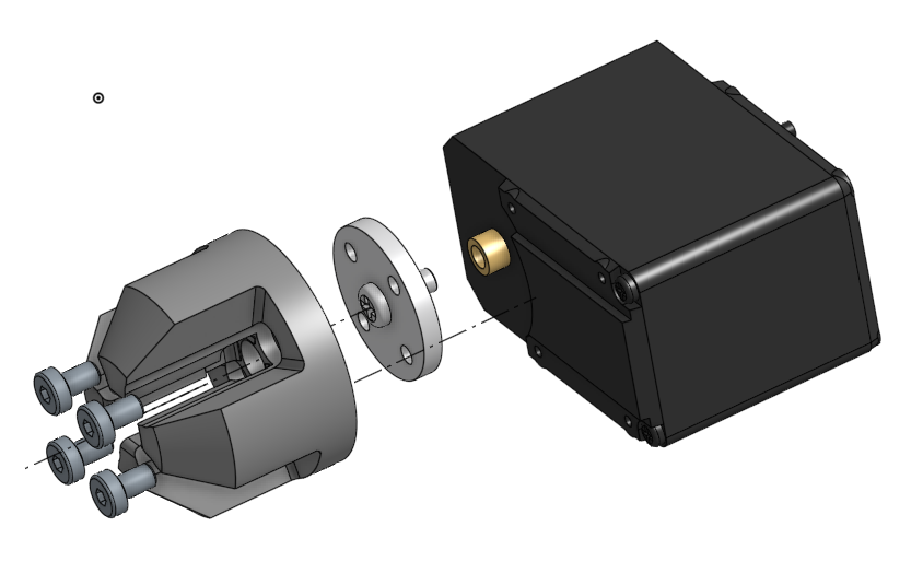
-
Insert the Feetech servo assembly into the servo bracket.
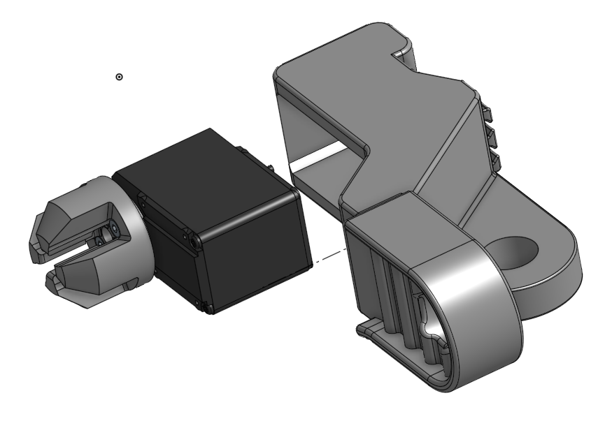
-
Attach the servo clamp to the back of the servo using two of the servo's screws.
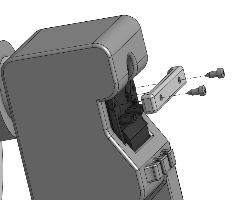
-
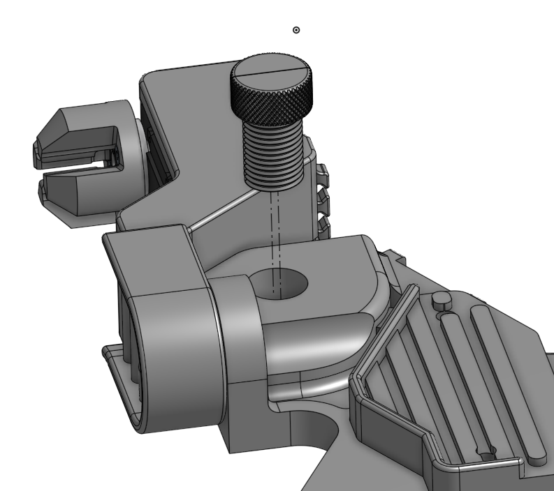
Place the arm base on top of the servo bracket. Run the main base bolt through the arm base and tighten it on the servo bracket.
-
Repeat for the other side.
| Part | Qty | Notes |
|---|---|---|
| Ball bearing | 12 | Supported Ball Bearing.stl |
| Bearing inner ring | 2 | Bearing Inner Ring.stl |
| Wheel bearing bracket | 1 each | Left · Right |
| Ball retainer | 2 | Ball Retainer.stl |
Assembly
-
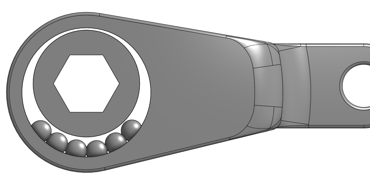
Insert all six ball bearings into the wheel bearing bracket, then slide in the bearing inner ring.
-
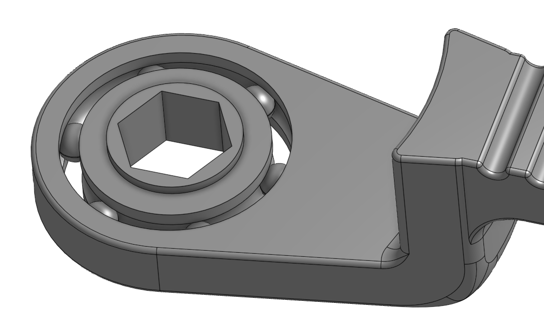
Push the bearing inner ring against the balls while turning it. Align the balls so they are spaced evenly at 60°.
-
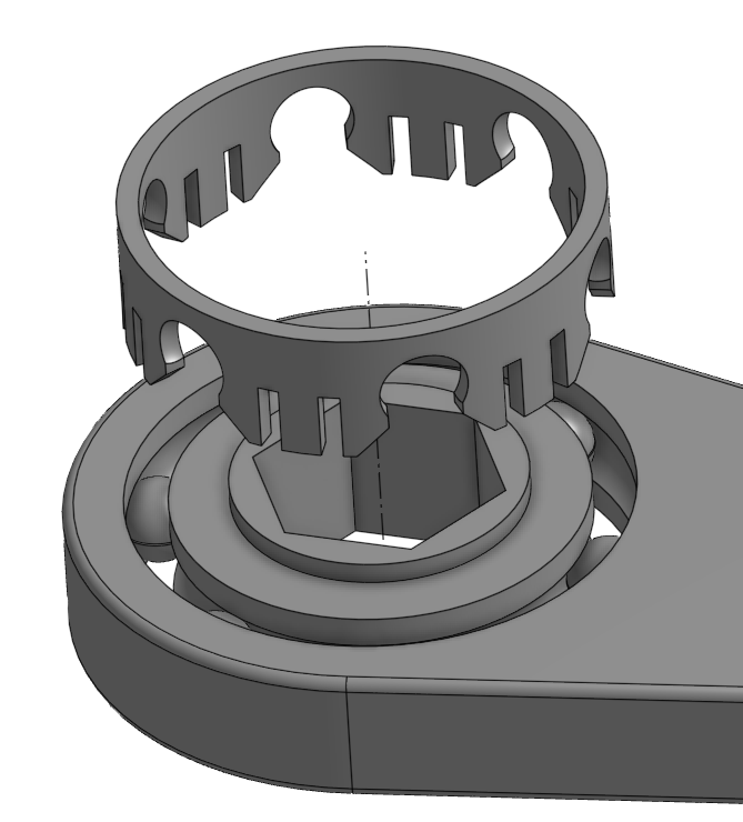
Push the ball retainer into the balls until it snaps into place.
-
Repeat for the other side.
| Part | Qty | Notes |
|---|---|---|
| Traction servo assembly | 2 | From Step 4 |
| Traction wheel bearing | 2 | From Step 5 |
| VEX shaft half | 4 | Front Axle Halve.stl |
| VEX Traction Wheel | 2 | VEX item 276-1497 |
| Front drive bolt | 2 | Front Drive Bolt v2.stl |
| Main base bolt | 2 | Main Base Bolt v2.stl |
Assembly
-
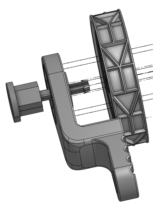
Insert the VEX shaft half into the VEX Traction Wheel, then into the traction wheel bearing. Note that the pointy bits of the ball retainer should be facing outside, and the flat circular face of the ball retainer should be facing inside.
-
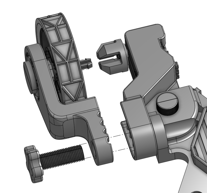
Align the axle end to face the servo coupler, then push the axle into the servo coupler until it clicks in place. Secure by locking the front drive bolt into the arm base side thread.
-
Repeat for the other side.
-
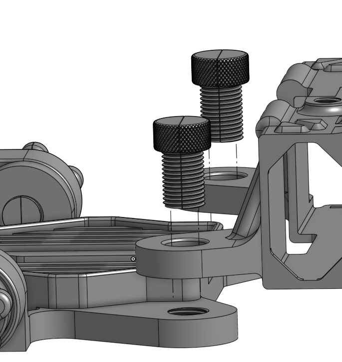
Use two main base bolts to attach the rear base to the arm base.
Build the follower arm per the official LeRobot SO-101 assembly guide (motor setup, joints, gripper).
| Part | Qty | Notes |
|---|---|---|
| Arm retainer pin | 8 | Arm Retainer Pin Halve.stl |
| Arm pin half bracket | 4 | Arm Pin Half Bracket.stl |
| Arm pin mini bracket | 4 | Arm Pin Mini Bracket.stl |
| Arm pin bolt | 4 | Arm Pin Bolt.stl |
Assembly
-
For each joint that needs a mid-travel pose, connect that servo, select its ID in settings, and press Center Servo to drive it to position 2048 (no EEPROM write).
-
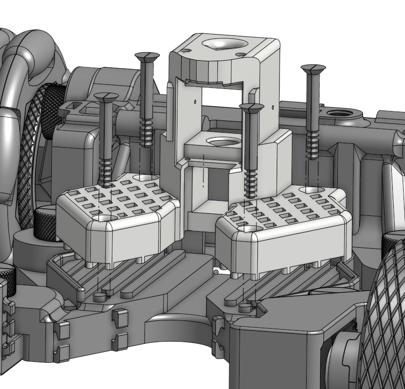
Mount the base of the SO101 follower arm to the chassis. Insert all four arm retainer pins all the way into the holes.
-
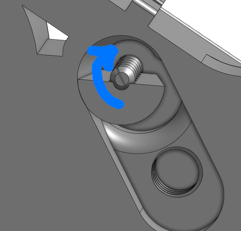
Insert the arm pin half bracket on one of the pins on the bottom of the chassis and rotate it until it reaches the back.
-
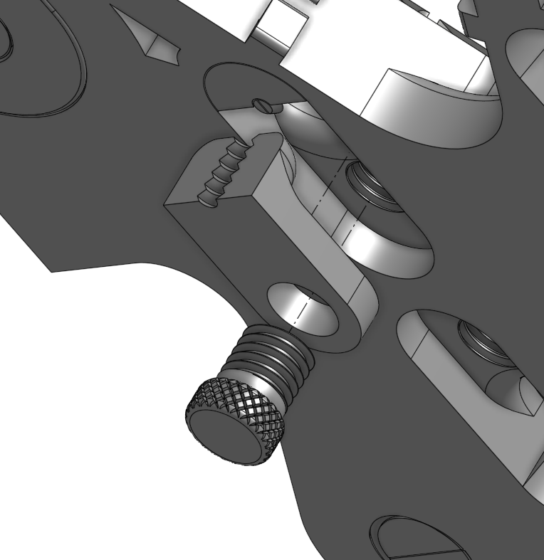
Push the arm pin mini bracket into place and fasten using the arm pin bolt.
-
Repeat 7.3 and 7.4 for all pins.
The two Feetech STS3215 traction-wheel servos ship with the factory ID. Each must be set to ID 7 (left) and ID 8 (right) before the robot is wired up. Use the SO101 Driver board (not the LCD board) and keep the two jumpers on B until the end of this section.
- Plug a USB-C cable from your computer into the SO101 Driver board.
- Plug in the barrel jack (battery / bench power) to the Driver Board.
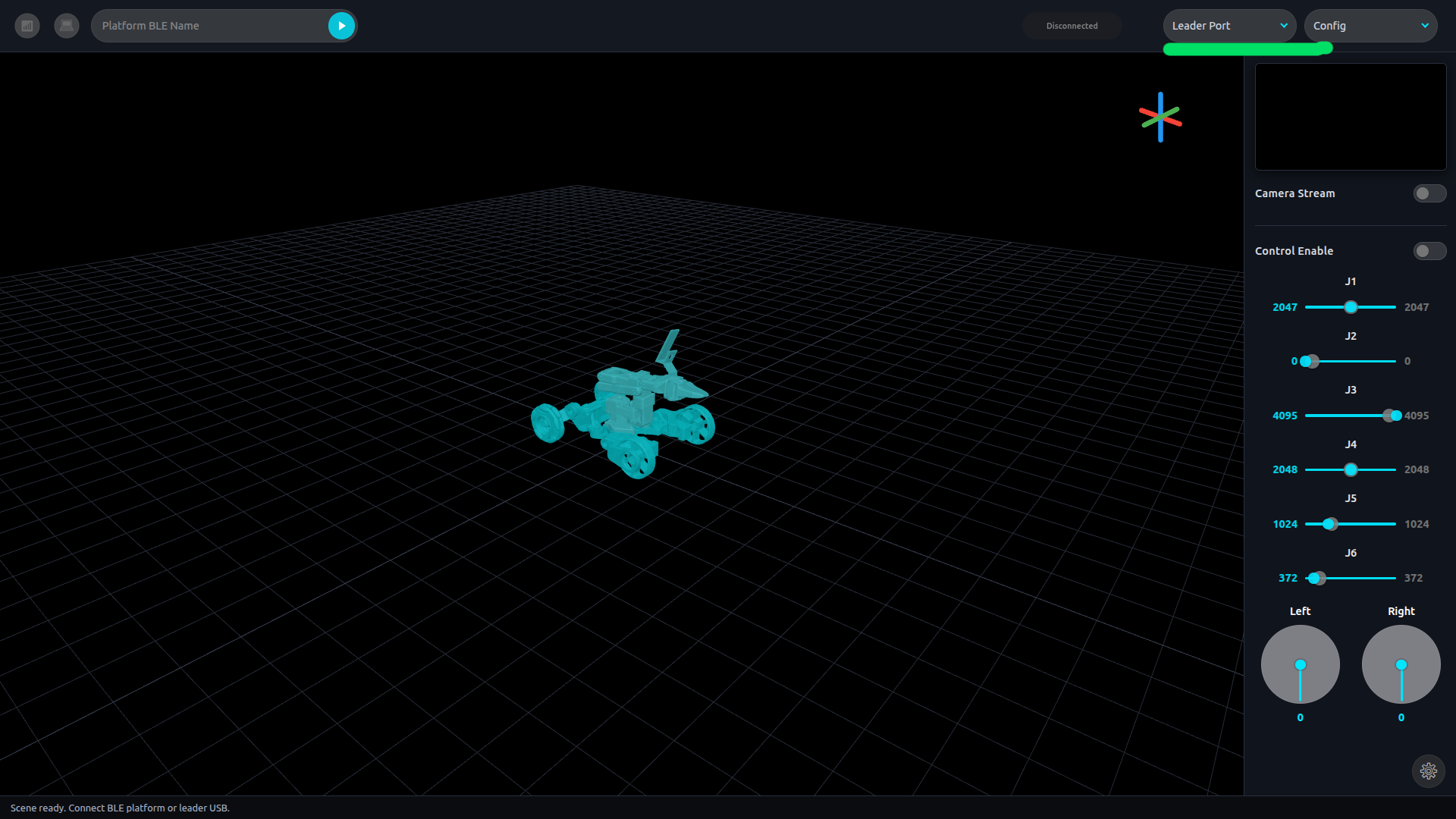
- Go to https://timrobot.github.io/SOBle/ on Google Chrome. Accept all permissions.
- Connect to the Driver board's port on the upper right hand corner by clicking on the Leader Port dropdown and selecting the proper port.
- Click on the settings button on the lower right hand corner.
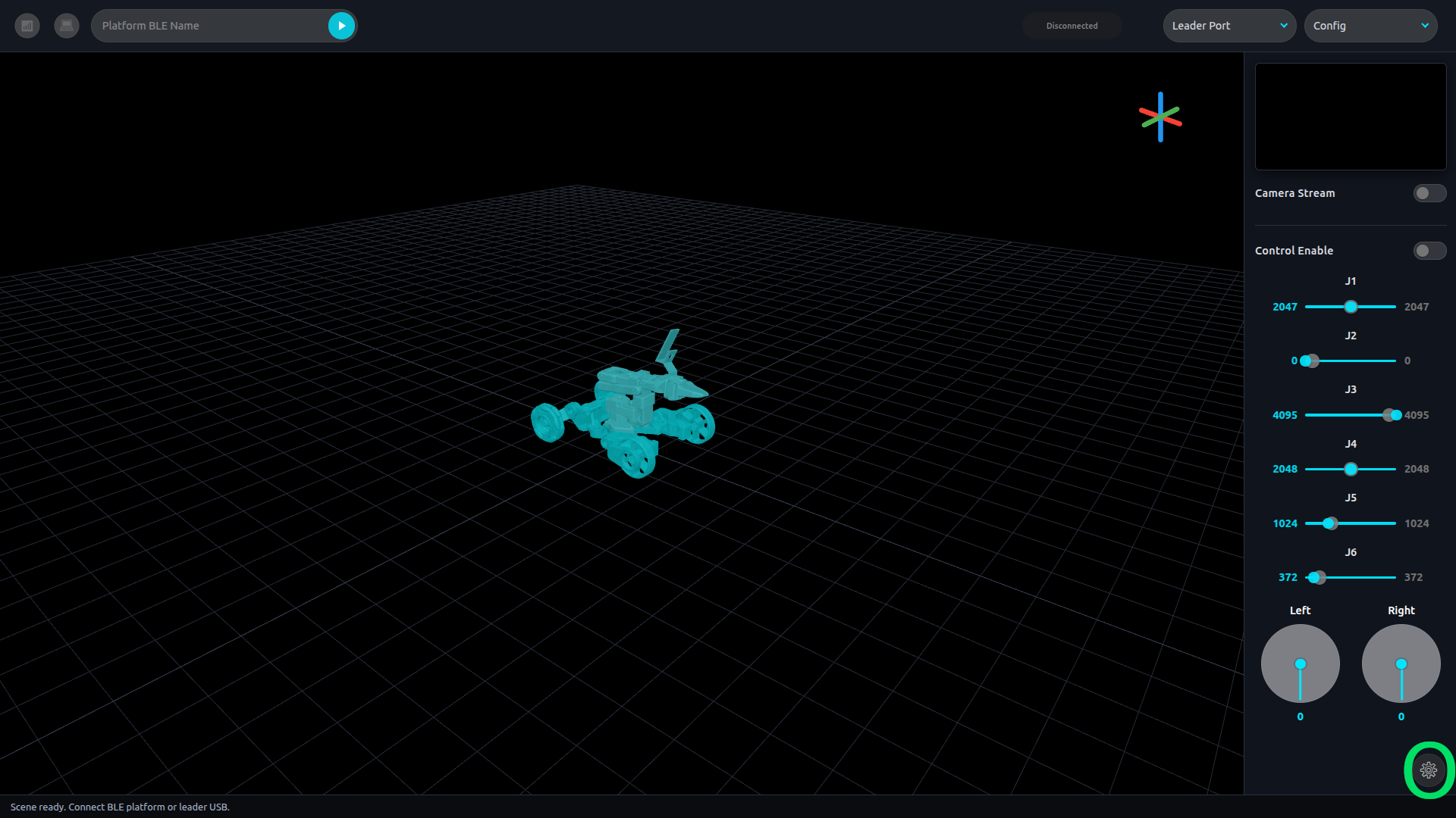
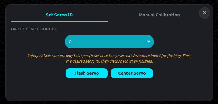
- Left motor only — plug the left servo into the driver bus, select 7 on the dropdown, Flash Servo, then unplug the left motor when the script says it succeeded.
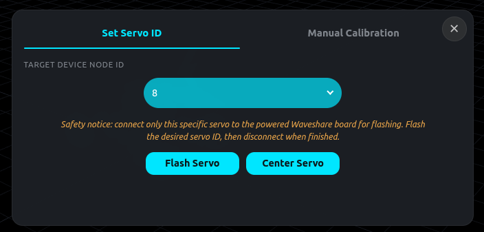
- Right motor only — plug the right servo into the driver bus, select 8 on the dropdown, Flash Servo, then unplug the left motor when the script says it succeeded.
- Unplug all power — disconnect the barrel jack and the USB-C cable from the SO101 Driver board.
- Wire J2 (servo 2) to the left traction motor.
- Wire the left traction motor to the right traction motor.
- Wire the right traction motor to J1 (servo 1).
If the board is already on the robot, do not power the robot. The SO101 Driver board may be damaged if the robot is powered without a shared ground.
-
Clone the SOBle repository on your laptop:
git clone https://github.com/timrobot/SOBle.git
-
Plug a USB-C cable from your computer to the LCD board.
-
Flash firmware — Open
esp32/So101-Platform/in the Arduino IDE (or your usual ESP32 toolchain). Add the esp32 boards library from the boards manager and GFX_Library_for_Arduino from the Library Manager. -
Apply the patch — before uploading, run from the repo (required for the Waveshare LCD on ESP32 core 4.x):
cd SOBle/esp32 ./patches/apply.sh -
On the port, select the ESP32-S3 Dev Module board type, click on the connected serial port, and upload the sketch. It should take around one minute.
-
Unplug the USB-C cable from the LCD board.
-
Insert the barrel connector and UBEC power wires into the XT60 female screw terminal, as shown in the diagram.
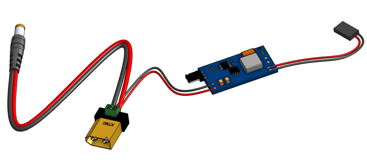
-
Optional. If you are planning to use the Raspi camera or you have hooked jumpers, you will have to do this. Be warned that this step is irreversible:
- Remove the header from the end of the UBEC.
- Insert the power wires into the USB-C female screw terminal, as shown in the diagram.
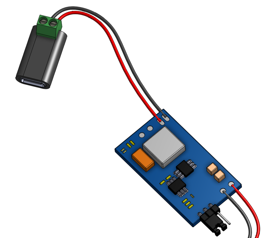
-
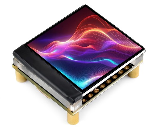
Solder the header pins onto the LCD board's right side. (You may skip this step if you are using hooked jumpers.)
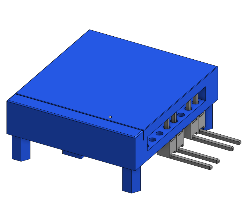
| Part | Qty | Notes |
|---|---|---|
| LCD (ESP32-S3) | 1 | From Step 9 |
| ESP32 Mount | 1 | ESP32 Mount.stl |
| M2 × 6 mm screw | 4 | From sourcing table |
| Rear base | 1 | From Step 3 |
| ESP32 bolt | 1 | ESP32 Bolt.stl |
| Bus adapter | 1 | Bus Adapter Bracket.stl |
| Bus adapter clamping foot | 2 | Bus Adapter Clamping Foot.stl |
| Bus adapter clamp bolt | 1 | Bus Adapter Clamp Bolt.stl |
| Bus adapter bracket top | 1 | Bus Adapter Bracket Top.stl |
| Bus adapter bracket bottom | 1 | Bus Adapter Bracket Bottom.stl |
| SO101 Driver board | 1 | From SO101 follower arm |
| Bus adapter bracket retainer | 1 | Bus Adapter Bracket Retainer.stl |
| Bus adapter retainer bolt | 1 | Bus Adapter Retainer Bolt.stl |
Assembly
-
Place the LCD onto the ESP32 Mount and insert four M2×6 mm screws.
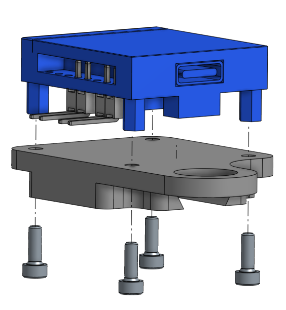
-
Slide the ESP32 Mount onto the rear base and secure with the ESP32 bolt.
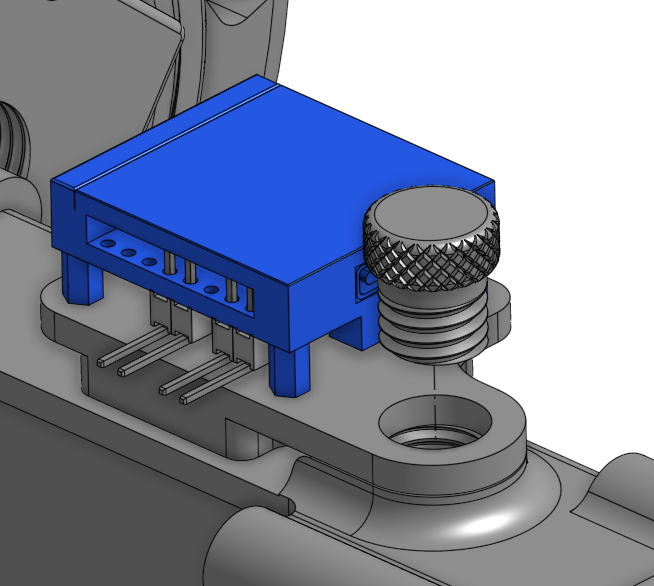
-
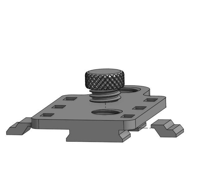
Secure the clamp feet to the bus adapter with the bus adapter clamp bolt.
-
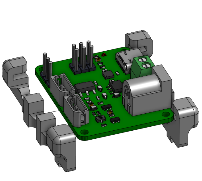
Clamp the top and bottom bus adapter brackets onto the SO101 Driver board.
-
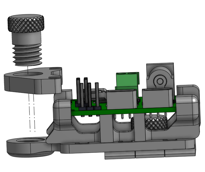
Insert the top and bottom bus adapter brackets into the bus adapter, slide on the bus adapter bracket retainer, and secure with the bus adapter retainer bolt.
-
Slide the bus adapter into the back of the SO101 arm.
-
Move the two jumpers on the SO101 Driver board from B to A.
-
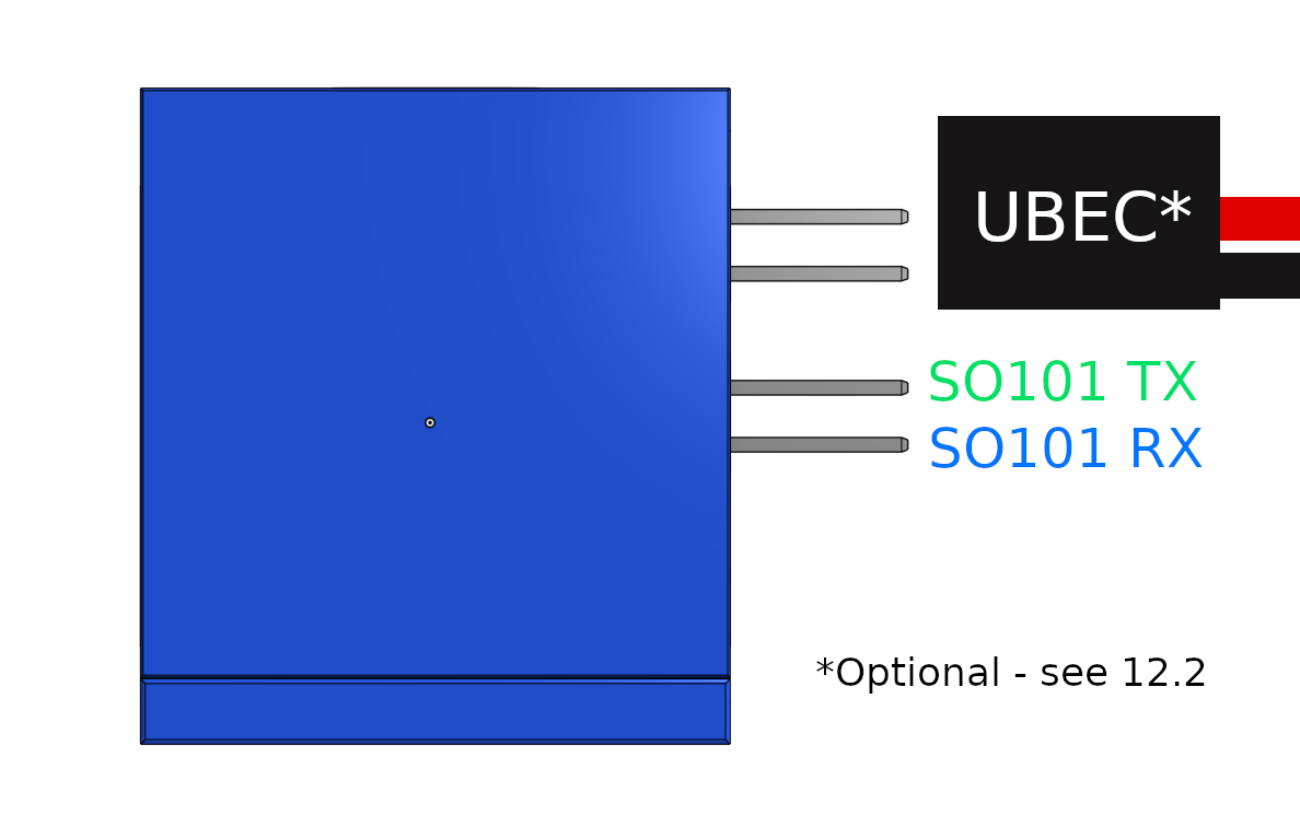
Attach the TX/RX jumper headers (or hooks) to the LCB board's right side (Diagram A), and then wire them to the SO101 Driver board (Diagram B).
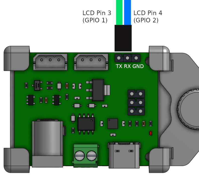
-
LCD connection options:
Configuration Instructions No Raspi camera, UBEC header Plug the header into the right side of the LCD board (as shown). No Raspi camera, UBEC USB-C Use a USB-C to USB-C cable from the UBEC to the LCD board. With Raspi camera Use a USB-C → µ-USB cable from the UBEC to the Raspi PWR. Use a µ-USB → USB-C cable from Raspi USB to the LCD board. (See Raspi camera attachment (optional) for camera assembly.) -
Plug the barrel connector into the SO101 Driver board.
-
Insert the 7.4 V battery into the battery cage and secure it with the battery lock (Battery Lock.stl).
- Plug the leader arm into your PC or Mac.
- Plug the XT60 male connector into the battery's XT60 female socket. This will power the robot.
- Go to Google Chrome and enable all Bluetooth/BLE flags.
- Go to https://timrobot.github.io/SOBle/. Read the robot name on the OLED. Type it in the search bar and press Connect.
- Control the robot using WASD and the leader arm.
WARNING: When you start the example below, the follower arm on the robot will immediately engage to match the joint mapping in your config file. Keep hands clear of the arm and make sure it has room to move before running.
-
Pip install the library if you have not already:
pip install "soble @ git+https://github.com/timrobot/SOBle.git@master" -
Read the robot name on the OLED. Then, on your PC or Mac:
cd examples python soble-app.py -p /dev/tty.usbmodem575E0032081 -n Capybara -c config.json-
-p— Leader port (Linux e.g./dev/ttyACM0, Windows e.g.COM3, macOS e.g./dev/tty.usbmodem575E0032081) -
-n— Robot name (e.g.Capybara) -
-c— Config file — leader/follower joint limits (see config.json)
-
-
Control the robot using WASD and the leader arm.
If you plan to add the Raspi camera attachment, print SO-ARM101_IMX708_wrist_mount.stl and mount it on the gripper as shown:
-
Camera to Pi — Connect the Arducam IMX708 camera module to the Raspberry Pi Zero 2 W camera port.
-
Mount Pi + camera — Secure the camera and Pi Zero 2 W to the cam mount.
-
SD card — Flash an SD card with Raspberry Pi OS. Setup the WiFi if you require video streaming.
-
AprilTag service — Boot the Pi, copy the
SOBle/raspitree onto it, and run:bash install-detect-atags-service.sh
(from
SOBle/raspi/). Then shut the Pi down.
Optional: Display an AprilTag such as this tag16h5 example on your phone — with the Raspi camera attached, you should see the tag detected in the UI.