EWCv3.3 Universal Web Kit
[TOC]
This document outlines the steps to configure the Universal Web Kit (U-Web kit) based on ESPEC Web Controller (EWC), Version 3, to connect to your existing chamber for control and instrumentation. EWC V3 is capable of communicating and controlling the following controllers: ESPEC P300, SCP220, ES102, Watlow F4 and F4T, Allen Bradley CompactLogix, ControlLogix and Micro8xx series.
Communication between EWC V3 and the existing chamber is accomplished via TCP/IP or USB-to-Serial interface. TCP/IP is the default communication protocol for Watlow F4T and HALT/HASS T-series chambers. Setup procedure for HALT/HASS T-series chambers is discussed in a separate document. The USB-to-Serial interface is for any chamber with ESPEC P300, SCP220, ES102 or Watlow F4.
The U-Web kit consists of the embedded computer in a black box, a DC power adapter, and an Ethernet cable and/or USB-to-Serial converter, as depicted in the following figure. In the setup process, the U-Web kit will be connected to your chamber using the TCP/IP or USB-to-Serial interface and the control PC via a DHCP or static network. The control PC will be used to access EWC via a Web browser to control and operate your chamber.

This section outlines the necessary steps to connect the U-Web kit to your chamber (equipped with P300, SCP220, ES102 or Watlow F4) using the USB-to-Serial adapter provided in the kit.
The setup involves four separate stages: (1) connecting the U-Web hardware (black box) to the chamber, (2) configuring the RS-232 communication protocol on the controller (Section 1.2), (3) configuring network connection (Section 3), (4) completing the Setup Wizard in the EWC software (Section 4).
-
Remove power to the chamber before servicing.
-
Ensure that the U-Web box is also disconnected from the DC power.
-
Connect the serial cable from the chamber to the USB-to-Serial interface, as depicted in the following figure.
-
Plug the USB cable into an open USB port on the U-Web box (marked USB0), as depicted in the following diagram.
-
Proceed to Section 1.2, 1.3, 1.4 or 1.5 that applies to the controller in your chamber.


To establish communication between EWC and P300, the RS-232 interface must have the correct settings. Complete the following steps to configure the RS-232 communication on the P300 controller.
-
Apply power to the chamber
-
Press Chamber Setup
-
Press Configuration
-
Press Set Communication
-
Press Set RS-232C Interface (option 2). Note: It may require enabling the RS-232C port via the Service menu option, if RS-232C communication port option does not appear on the Set Communication menu as depicted in Figure [fig:p300a].
-
Press Chamber Setup
-
Press Configuration
-
Press Service, enter the password 335, twice. Note: The first attempt results in “invalid password” or “entered password is incorrect.” Ignore the message and enter 335 again.
-
Press System Configuration
-
Press Menu (at the bottom)
-
Select the “OP 3” option.
-
Select the “RS-232C” button.
-
Set the “LAN” option to ON.
-
Press Close at the bottom of the screen; cycle power to the chamber.
-
-
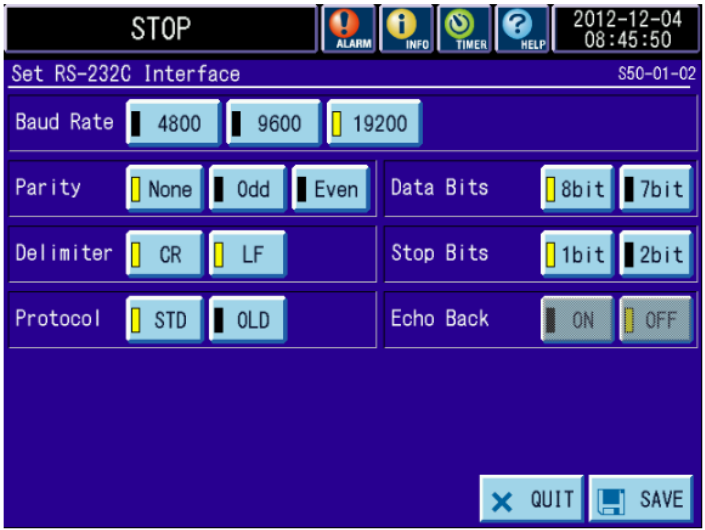
Confirm that the RS-232C settings are exactly as depicted in Figure [fig:p300b].
-
Press Save
-
Proceed to Section 3 to complete a network setup.

To establish communication between EWC and SCP220, the RS-232 interface must have the correct settings. Complete the following steps to configure the RS-232 communication and Time Signals on the SCP220 controller.
-
Apply power to the chamber
-
Press Chamber Setup
-
Press Configuration
-
Press Communication Setup (option 1)
-
Press RS-232C Setup
-
Set Delimiters CR and LF to On; Transmission rate to 9600; Parity to none; Data bits to 8bit; Stop bits to 1bit; Protocol to STND. Refer to the following figure for detail.
-
Press Prev. Screen to save setting and return to the Main Menu.

-
Apply power to the chamber
-
Press Chamber Setup
-
Press Configuration
-
Press Service (option 11)
-
Enter password: 3132
-
Press System Configuration (option 1)
-
Press Time Signals (option 7)
-
Confirm that all Time Signals are turned on as depicted in the following figure. If number 9, 11 and 12 are not assigned to Time Signal #, leave settings on to keep current chamber operation.
-
Press Prev. Screen to save setting and return to the Main Menu.
-
Proceed to Section 3 to complete a network setup.

The RS-232 communication setting on ES102 uses the same baud rate as that in SCP220 controller, which is 9600. Refer to the ES102 Operations manual for detail. Proceed with the following steps to confirm the settings:
-
Apply power to the chamber
-
Press SET on the panel repeatedly until SYSTEM is lid in green and USEr Con is displayed on the HMI panel.
-
Press NEXT twice to confirm the display: SPEd 96.
-
Press NEXT again to confirm the display: STop 1.
-
Press NEXT again to confirm the display: dAtA 8.
-
Press NEXT again to confirm the display: PrtY non.
-
Press NEXT again to confirm the display: dEL CL.
-
Press NEXTagain to return to the SYSTEM menu.
-
Press SET several times until it returns to the MONITOR menu.
-
Proceed to Section 3 to complete a network setup.
The RS-232 communication setting on F4 uses the same baud rate as that in SCP220 controller, which 9600. Refer to Watlow F4 Operations manual for detail on the serial communication setting.
Proceed to Section 3 to complete a network setup.
TCP/IP is the default communication interface between EWC and your chamber with F4T. The setup involves four separate stages: (1) connecting the U-Web hardware (black box) to the chamber (Section 2.1), (2) configuring the TCP/IP static network on the F4T (Section 2.2), (3) configuring network connection (Section 3), (4) completing the Setup Wizard in the EWC software (Section 4).
Complete the following steps to connect the EWC U-Web hardware (black box) to your chamber/F4T.
-
Remove power to the chamber before servicing.
-
Ensure that the EWC U-Web box is disconnected from the DC power.
-
Plug the Ethernet cable (supplied with the kit) into the Ethernet port on your chamber (marked ETH-1), as depicted in the following figure.
-
Plug the other end of the Ethernet cable into the Ethernet port on the EWC U-Web box (marked ETH-1), as depicted in the following diagram by matching the marked ports depicted in the above figure.
-
Proceed to Section 2.2 to configure the internal network on the F4T.


Apply the following procedure to configure the F4T to use a static IP address to set up a special internal network between EWC U-Web and the chamber/F4T.
-
Apply power to the chamber/F4T
-
Press the Menu button on F4T to access its Main Menu.
-
From the Main Menu, press Settings
-
Press Network
-
Press Ethernet to access IP Address Block, as depicted in the following figure.
-
Press DHCP in the IP Address Mode (depicted the above figure).
-
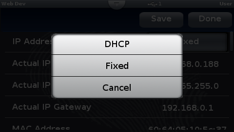
On the pop-up window, as depicted in the following figure, press Fixed to set the IP Address Mode from DHCP to Fixed.
-
Swipe the screen upward to get to the IP Fixed Address block and enter the following numbers in Part 1-4, as depicted in the following figure.
- Part 1: 10
- Part 2: 30
- Part 3: 200
- Part 4: 242
-
Swipe the screen upward to get to the IP Fixed Subnet block and enter the following numbers in Part 1-4, as depicted in the following figure.
- Part 1: 255
- Part 2: 255
- Part 3: 255
- Part 4: 240
-
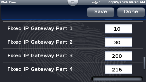
Swipe the screen upward to get to the IP Fixed Gateway block and enter the following numbers in Part 1-4, as depicted in the following figure.
- Part 1: 10
- Part 2: 30
- Part 3: 200
- Part 4: 216
-
Swipe the screen upward to the Modbus configuration section and set parameters as shown in the following figure.
-
Press Save to save the settings.
-
Press Done to exit the network configuration and return to the Main Menu.
-
Reboot the F4T to ensure the new settings are applied. This power cycling allows the F4T to broadcast its new IP address to be picked up by EWC V3.
-
Proceed to Section 3 to complete a network setup.


EWC U-Web can be set up to operate on a DHCP or static network. Apply one of the following procedures to configure your system.
This section outlines the steps to set up a Class C static network between EWC and your PC. This setup affords the benefit that EWC does not have to be part of a network. A PC directly connected to the EWC U-web can access EWC directly to control and operate the chamber.
Complete the following steps to set up a static network between the EWC U-Web and your PC.
-
Chamber/controller may still remain on from Section 1 or Section 2. Ensure that power is applied to the chamber/controller.
-
Plug the Ethernet cable (supplied in the kit) to the Ethernet port on the EWC U-Web box (marked ETH-0), as depicted in the following diagram.
-
Plug the other end of the Ethernet cable (from ETH-0) directly into the Ethernet port on your PC (marked ETH-A). This connection establishes a direct communication between EWC and your PC. Note: Modern devices can connect directly to each other with a standard CAT 5/6 cable without the need for a cross-over cable.
- USB-to-Serial: The complete setup with static network and serial communication is depicted in the following diagram.
- TCP/IP: The complete setup with static network and TCP/IP communication is depicted in the following diagram.
-
Plug the barrel jack from the DC power adapter (supplied with the EWC kit) into the EWC black box labeled Power to boot EWC. Boot process will complete within 2-3 minutes.
-
Proceed to Section 3.1.2 to configure a static IP address on your PC.


EWC is preconfigured to use a Class C static network protocol with the following settings:
     IP Address:  192.168.0.83     (called fallback static IP)
     Subnet Mask: 255.255.255.0
     Gateway:     192.168.0.1
This protocol occurs when EWC is connected directly to a computer or a network hub without DHCP service.
In order for the PC to communicate with EWC, it must also use a Class C static network protocol configured as follows:
     IP Address:           192.168.0.84  (recommended IP)
     Subnet Mask:          255.255.255.0
     Gateway:              192.168.0.1
     Preferred DNS server: 8.8.8.8
     Alternate DNS server: 8.8.4.4
Complete the following steps on MS Windows 8/10/11:
-
Hold down the Windows key and press R to launch the Run Command dialog box.
-
Enter ncpa.cpl into the Open box field and press Enter or click .
-
Point and Right-Click the “Local Area Connection” icon, then click Properties from the drop-down menu (see the following figure). Verify that the correct Ethernet port is selected, if your PC has multiple ports.
-
In the “Local Area Connection Properties” window, confirm or place the check mark in front of “Internet Protocol Version 4 (TCP/IPv4)”(see Figure below).
-
Click to highlight “Internet Protocol Version 4 (TCP/IPv4)” and then click Properties in the lower-right corner.
-
In the “Internet Protocol Version (TCP/IPv4) Properties” window, turn on the radio button for “Use the following IP address:” and enter these settings (see Figure below for detail):
IP Address: 192.168.0.84 Subnet Mask: 255.255.255.0 Gateway: 192.168.0.1 -
In the “Use the following DNS server addresses:” section, enter the following settings (see Figure below):
Preferred DNS server: 8.8.8.8 Alternate DNS server: 8.8.4.4 -
Turn on “Validate settings upon exit” with a check mark and click OK.
-
Click OK to close “Local Area Connection Properties” window.
-
Close out the Network Connections window.
-
Open a Web browser and navigate to: http://192.168.0.83/ to access EWC.
-
The user interface of EWC appears in the Web browser as depicted in the following figure.
-
Proceed to Section 4 to complete the initial setup of EWC and begin operating your chamber.


This setup affords the benefit that EWC U-Web can be accessed from any computer on the network to control and operate the chamber. Complete the following steps to connect EWC U-Web to your DHCP network.
-
Chamber/controller may still remain on from Section 1 or Section 2. Ensure that power is applied to the chamber/controller.
-
Plug the Ethernet cable (supplied in the kit) to the Ethernet port on the EWC U-Web box (marked ETH-0), as depicted in the following diagram.
-
Plug the other end of the Ethernet cable (from ETH-0) into an open port on the main network router, as depicted in the following figure. This Ethernet cable can be plugged directly into the Ethernet port on a PC (marked ETH-A) for a direct communication via a static network protocol.
- USB-to-Serial: The complete setup with DHCP network and serial communication is depicted in the following diagram.
- TCP/IP: The complete setup with DHCP network and TCP/IP communication is depicted in the following diagram.
-
Plug the barrel jack from the DC power adapter (supplied with the EWC kit) into the EWC black box labeled Power to boot EWC. Boot process will complete within 2-3 minutes.
-
Launch a Web browser on the control PC (or any PC on the network) and navigate to http://especSN#.local/ to access EWC, where SN# is the chamber serial number (see the following figure).
Example: http://espec1700015835.local/
If access fails, try the default hostname: http://espec-default.local//
-
The user interface of EWC appears in the Web browser, as depicted in the following figure.
-
Proceed to Section 4 to complete the initial setup of EWC and begin operating your chamber.


When EWC is powered on for the first time, it presents a Setup Wizard for post installation that includes e-mail alert and/or password recovery, password reset and network settings.
IMPORTANT NOTE: If you click SKIP on any of the following Setup Wizard pages, they will reappear every time you restart and log into EWC.
A log-in screen is depicted in the following figure. If an error in red appears in the background, chamber interface has not been set up properly. Section 4.3 on Chamber Configuration and Confirmation will go over the setup procedure.
Enter username and password:
   username: admin
   password: admin
and click to log in.
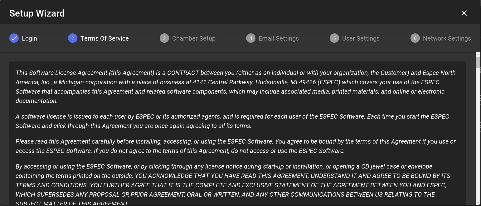
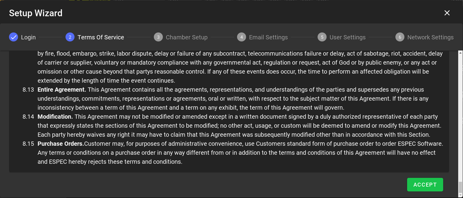
Apply the scroll bar to read through the Terms of Service, then click to accept the terms.
Chamber configuration status may display communication error in the Email settings page as shown in the following figure. If the Email settings page displays the chamber status without any errors, proceed to the next section. Otherwise, click the button to return to the Chamber Setup page to confirm or reconnect the chamber with the correct model, type and options. Proceed to configure the chamber interface with the following steps using the following figure as a reference. Example is shown for a Mechanical HALT chamber with P300.

-
Confirm or select EQ: Mechanical HALT Chamber under the Chamber Category.
-
Select Model/Type as shown. Refer to your chamber operation manual for this information.
-
Verify and confirm that the interface type is Serial with baud rate 19200. Serial port should be .
-
Under the Optional Features column, check any box that applies to your chamber.
-
Click ACCEPT to apply the settings.
-
Click APPLY DEFAULTS in the pop-up window.

Once chamber connection has been established, the Setup Wizard returns (i.e., forwards) to the Email Setting page as depicted in following figure.
For a standalone system, this setup page can be left with its default setting. Click in Figure [email-setting] to continue.
For a networked system, and if this system has access to the Internet, alert e-mail and account recovery e-mail can be configured at this time. However, these settings can be configured later using the Settings menu. This setup page can be left with its default setting. Click ACCEPT in the Figure to continue.

It is imperative that the admin password be changed to something secure to protect both your chamber and EWC. The following figure presents a first chance to reset the admin password.
-
Enter current password: admin
-
Enter new password twice.
-
Click ACCEPT.

NOTE: An error message, as depicted in Figure below, will be displayed if the admin password has not been reset. You can still use the factory password but you will put your system at high risks of security breach. This admin password can be reset later via the Settings menu.

The Network Settings page displays hostname and network protocol (DHCP or static) and fallback static IP settings assigned to the ETH-0 port of EWC (called eth0), as depicted in the following figure.

The DHCP box is checked by default such that EWC is ready to use DHCP when it detects one. The IP address leased by a DHCP server to EWC can be found under the Network Settings submenu (under Settings in the menu bar). If DHCP is not detected (or not available), EWC uses its fallback static IP address (192.168.0.83) as shown in [network-info]. The DHCP box is still checked when EWC uses its fallback static IP settings.
-
Click to continue.
-
The Setup Wizard is complete. EWC now displays its home page in Overview mode and is ready for chamber operation. Single-User or Multi-User:
-
If multiple operators need to control and operate the chamber, they each should have a separate account on the system. Consult our ESPEC Web Controller User’s Manual which can be found in Section 5 for detail on how to create different accounts and privileges for these operators.
Users may begin to log into EWC to operate the chamber as soon as their account has been created.
-
If this is a single-user system, EWC is now ready for operation. Refer to Section 5 for detail on how to access the online wiki manual or the embedded PDF manual under the About menu.
A static network other than a Class C type can be set on EWC. The configuration of such static network can be done by using either static or DHCP in Section 3 as a starting point. If your IT requires that each device on the main network must use a static IP address (even on DHCP network), the best approach would be to start from Section 3.
Complete the following steps:
-
Obtain the complete IP information from your IT. Refer to following figure as a example.
-
Log in as admin.
-
Click Settings (in the menu bar).
-
Click Network Settings (in the submenu bar).
-
Uncheck the DHCP box.
-
Edit the IP address field (replacing 192.168.0.83 with a new value). Refer to Figure below as an example.
-
Enter the appropriate values for Net Mask, Gateway, DNS1 and DNS2.
-
Click Save in upper-right corner.
-
Open a new Web browser and navigate to EWC with the new IP address.

Warning! To revert EWC to use DHCP protocol and its preconfigured static network setting, you must check the DHCP box and also enter 192.168.0.83 in the IP address field (and save the settings) before you reboot and connect EWC back to a DHCP or Class C static network. If you failed to apply these settings, EWC will still be using the custom static IP address as its fallback static network protocol.
The Operation Manual for ESPEC Web Controller is available in two formats, embedded PDF and online wiki.
-
Embedded PDF: The embedded PDF is accessible from the MANUAL tab under the About menu, as depicted in the following figure. To view the PDF manual, access the buttons according to the numbered labels in the figure.
-
Online Wiki: The EWC User Manual for the specific controller can be view online here:
