Minimal‐Example‐Wago750‐501
The WAGO 750-501 Digital Output Example is a minimal demonstration showing how to set the digital outputs on a WAGO 750-501 EtherCAT terminal using the QiTech machine framework. It represents one of the simplest possible hardware interactions in the system: Controlling 2 Digital Outputs using the QiTech Control Dashboard. Each output state is also reflected by the built-in LED on the terminal — no additional wiring is required to observe the output.
- WAGO 2787-2144 EtherCAT
- WAGO 750-354 EtherCAT Coupler
- WAGO 750-602 EtherCAT Power Terminal
- WAGO 750-501 EtherCAT Terminal (2-Channel Digital Output)
- WAGO 750-600 EtherCAT Endmodule
- WAGO 852-1322 Ethernet-Switch
- 24V DC Lab power supply (AC/DC adapter)
- A Linux PC (Ubuntu/Debian recommended)
- Standard Ethernet cable
See Device Example Basics for software prerequisites.
⚠️ Always disconnect power before wiring. See Device Example Basics for the safe wiring procedure.
We supply power to the other devices by using the 750-602 EtherCAT Power Terminal
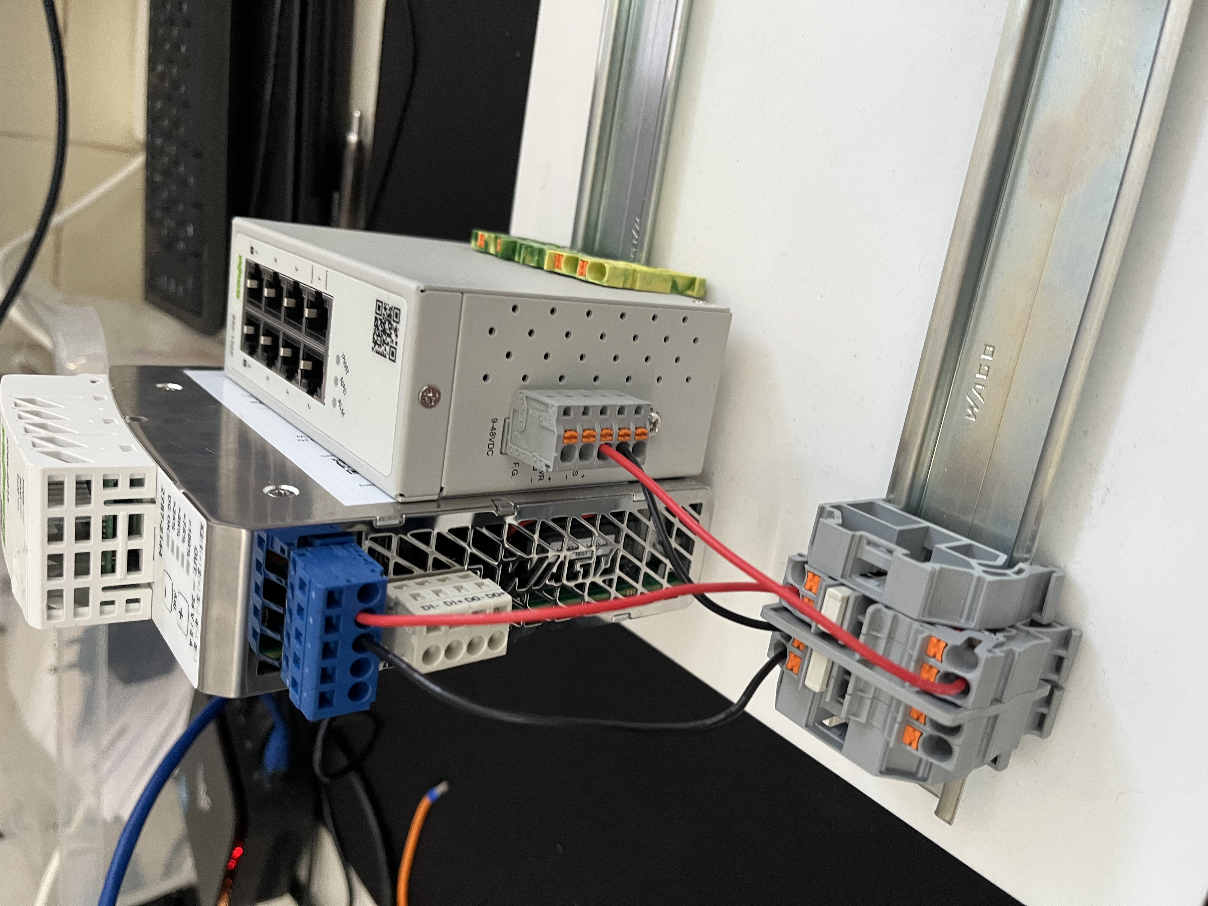
Perform the following wiring on the Ethernet-Switch:
- Red wire (+24V) → PWR+
- Black wire (0V) → RPS-
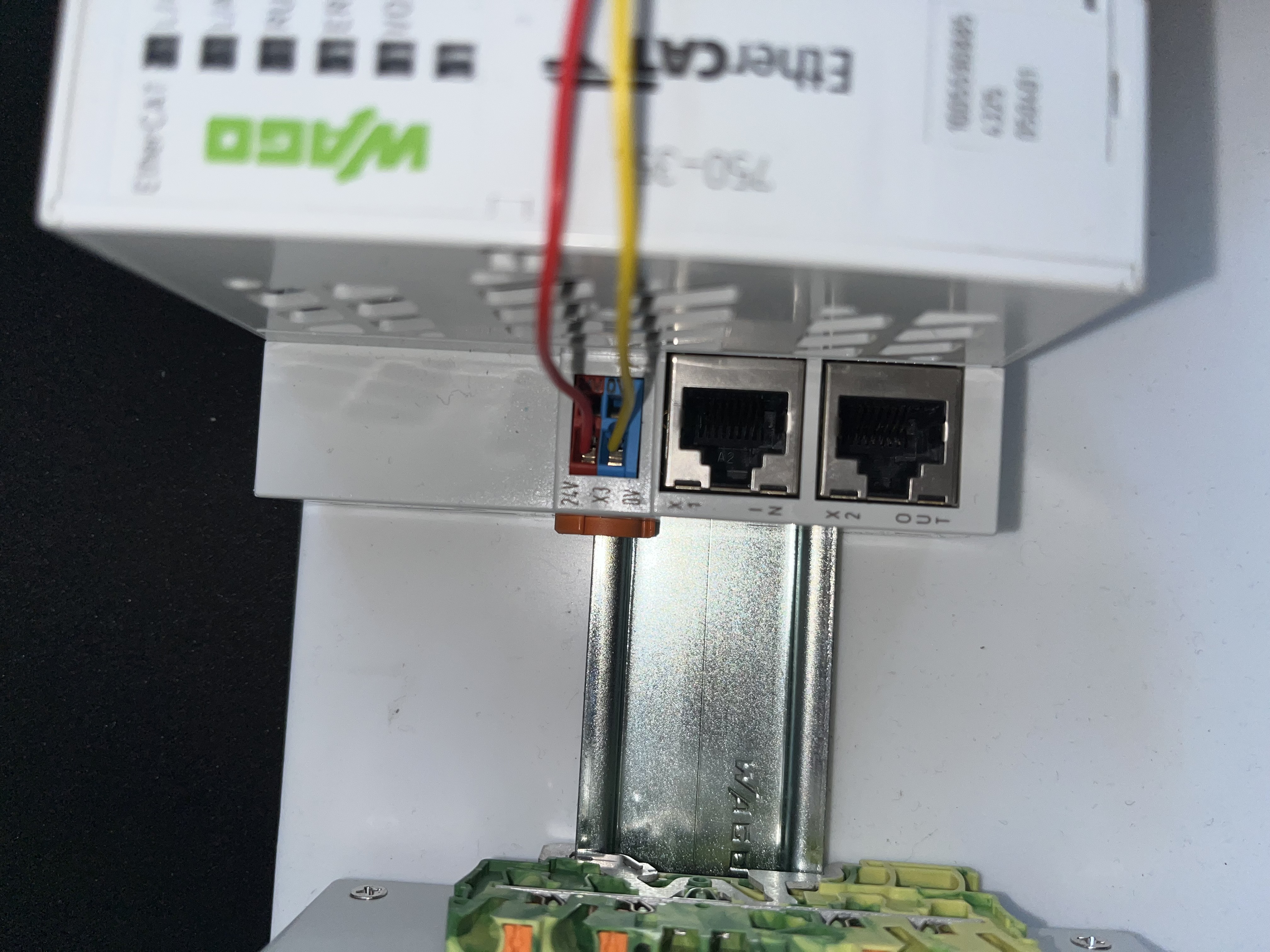
Wire the 750-354 EtherCAT Coupler to the power supply:
- Red wire (+24V)
- Yellow wire (0V)
Slide the 750-602 EtherCAT Power Terminal onto the right side of the 750-354 Coupler until it locks.
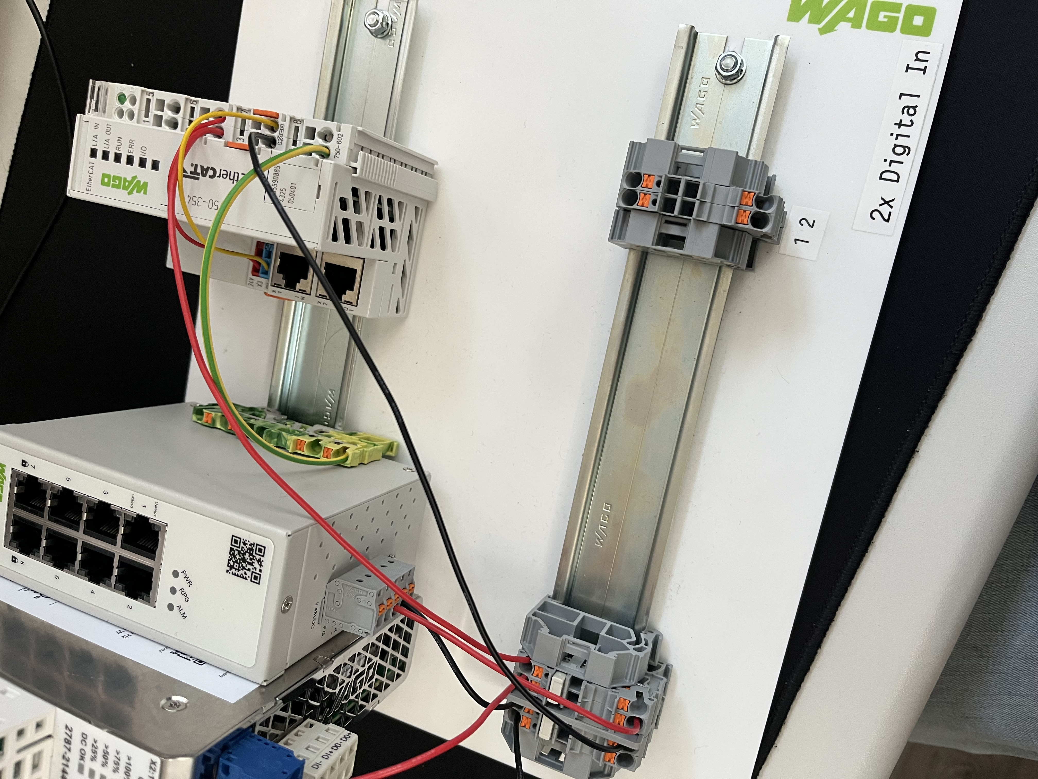
Perform the following wiring steps:
- Green wire (Ground) → Terminal 4
- Red wire (+24V) from 750-602 EtherCAT Power Terminal → Terminal 2
- Black wire (0V) from 750-602 EtherCAT Power Terminal → Terminal 3
- Red wire (+24V) from 750-354 EtherCAT Coupler → Terminal 6
- Yellow wire (0V) from 750-354 EtherCAT Coupler → Terminal 7
Slide the 750-501 EtherCAT Terminal onto the right side of the 750-602 EtherCAT Power Terminal until it locks.

The terminal receives its power through the pin connectors — no additional wiring is required. The output state of each channel is visible via the built-in LED on the terminal face.
Slide the 750-600 EtherCAT Endmodule onto the right side of the 750-501 EtherCAT Terminal until it locks.
No further wiring is required.
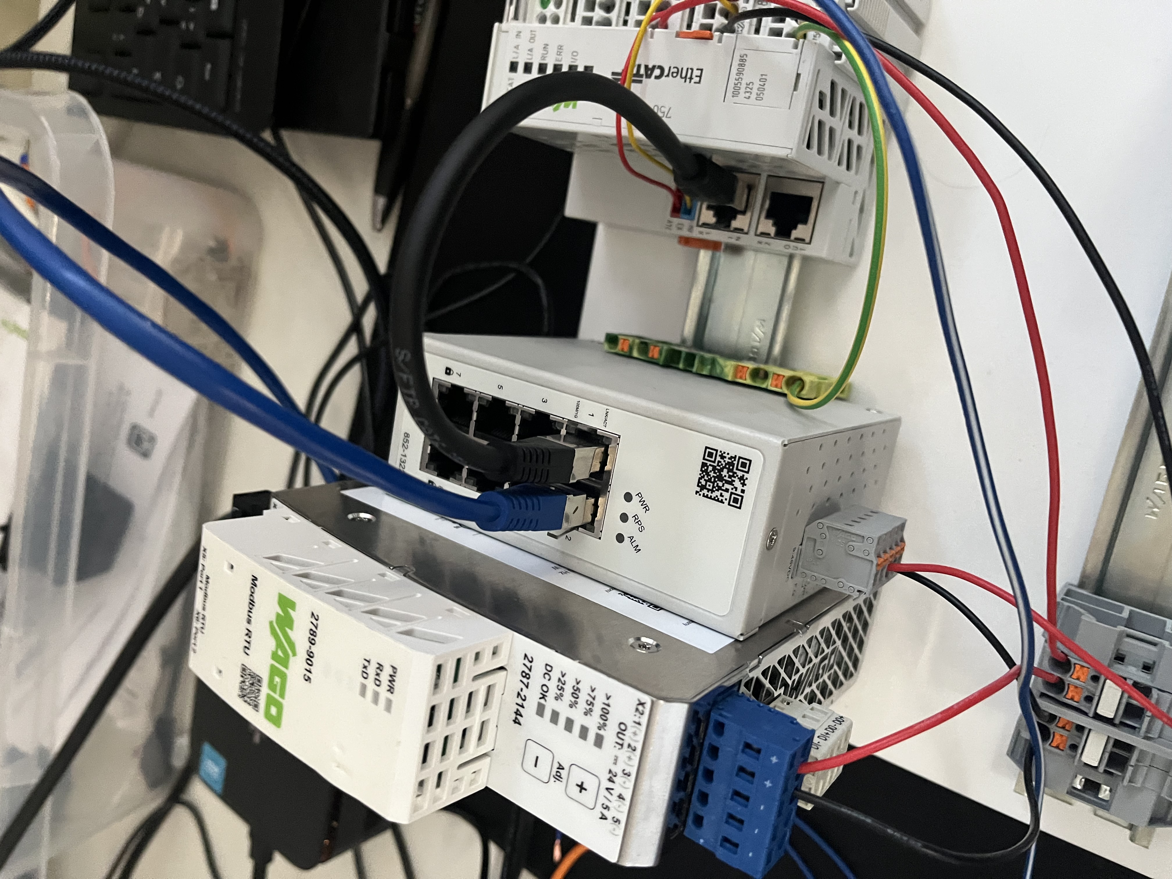
Connect the 2787-2144 power supply to the power outlet.
Use a standard LAN cable to connect your PC → 852-1322 Ethernet-Switch
And another from 852-1322 Ethernet-Switch → 750-354 EtherCAT Coupler
See Device Example Basics to install and run the software, then return here for the device-specific demo steps.
Once the backend + frontend are running, you should see:
-
WAGO750-354 (Coupler)
-
WAGO750-501 (2CH DO)
Steps:
-
Click Assign on the 750-354 module
-
Select "Wago 750-501 DO Test V1"
-
Enter a serial number other than 0
-
Keep the device role unchanged if it is set to "Wago 750-354 Bus Coupler"

- Repeat these steps for the 750-501 module using the same non-zero serial number

- Finally, restart the Backend process
In the left sidebar, Wago 750-501 DO Test should appear. Click it.

You will see two output channels — Do1 and Do2 — each with an On/Off toggle.

Toggling an output to On activates the corresponding channel and lights up the LED on the 750-501 terminal face. Toggling it to Off deactivates the channel and turns the LED off.
A Master Output Control panel is also available to turn all outputs on or off simultaneously.