Minimal‐Example‐Wago750‐530
Complete Hardware + Software Walkthrough
Modern industrial PLC systems use distributed fieldbus I/O modules such as the WAGO 750-530 to interface with real-world signals. These modules extend the controller by providing physical input and output channels.
I/O modules exist in various types, including:
- Analog inputs
- Analog outputs
- Digital inputs
- Digital outputs
From a programming perspective, each channel corresponds to a mapped variable inside the control system.
The WAGO 750-530 provides eight digital output channels, each represented as a boolean value (true / false). These outputs can be used to:
- Switch relays
- Control indicator lights
- Drive contactors
- Activate external devices
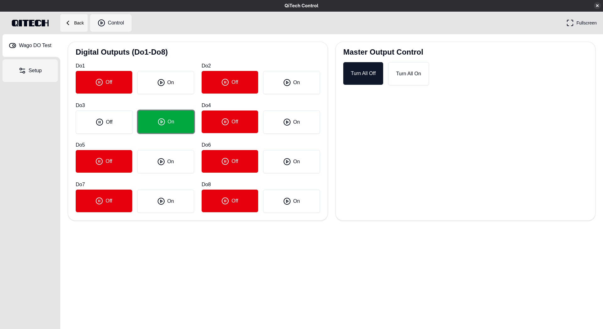
This example demonstrates the simplest possible interaction: toggling the output values on and off using the QiTech Control frontend and observing the corresponding physical signal changes on the module.
- WAGO 750-530 (8-channel digital output)
- WAGO 750-602 EtherCAT Power Terminal
- WAGO 750-354 EtherCAT Coupler
- WAGO 750-600 End Module
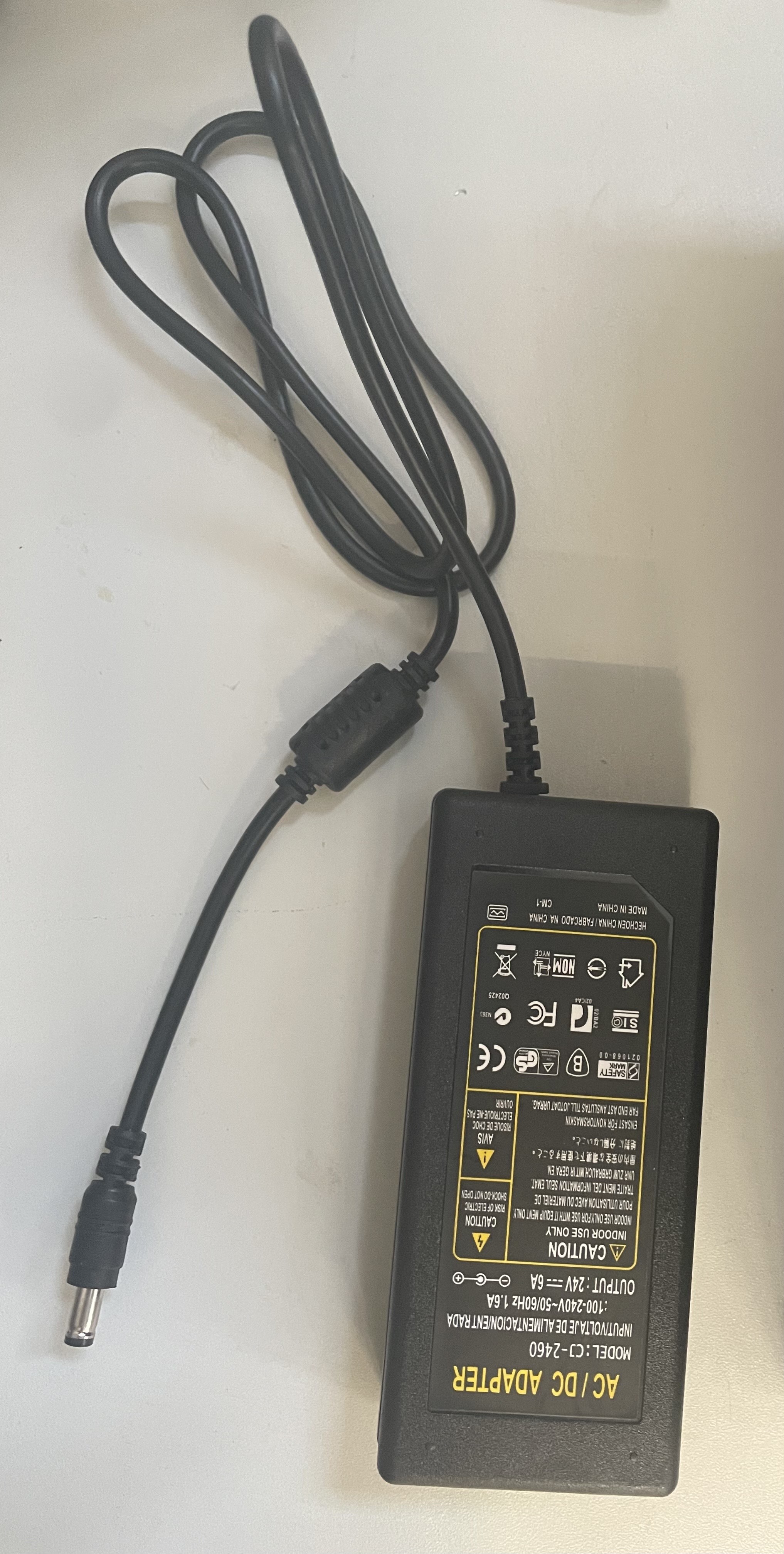
- 24 V DC power source (AC/DC adapter with 24 V output is sufficient)
- Connecting wires (0.5–1.5 mm² recommended)
- DC hollow plug
- Linux PC (Ubuntu/Debian recommended)
- Ethernet cable
- Flat-head screwdriver
See Device Example Basics for software prerequisites.
⚠️ Always disconnect power before wiring. See Device Example Basics for the safe wiring procedure.
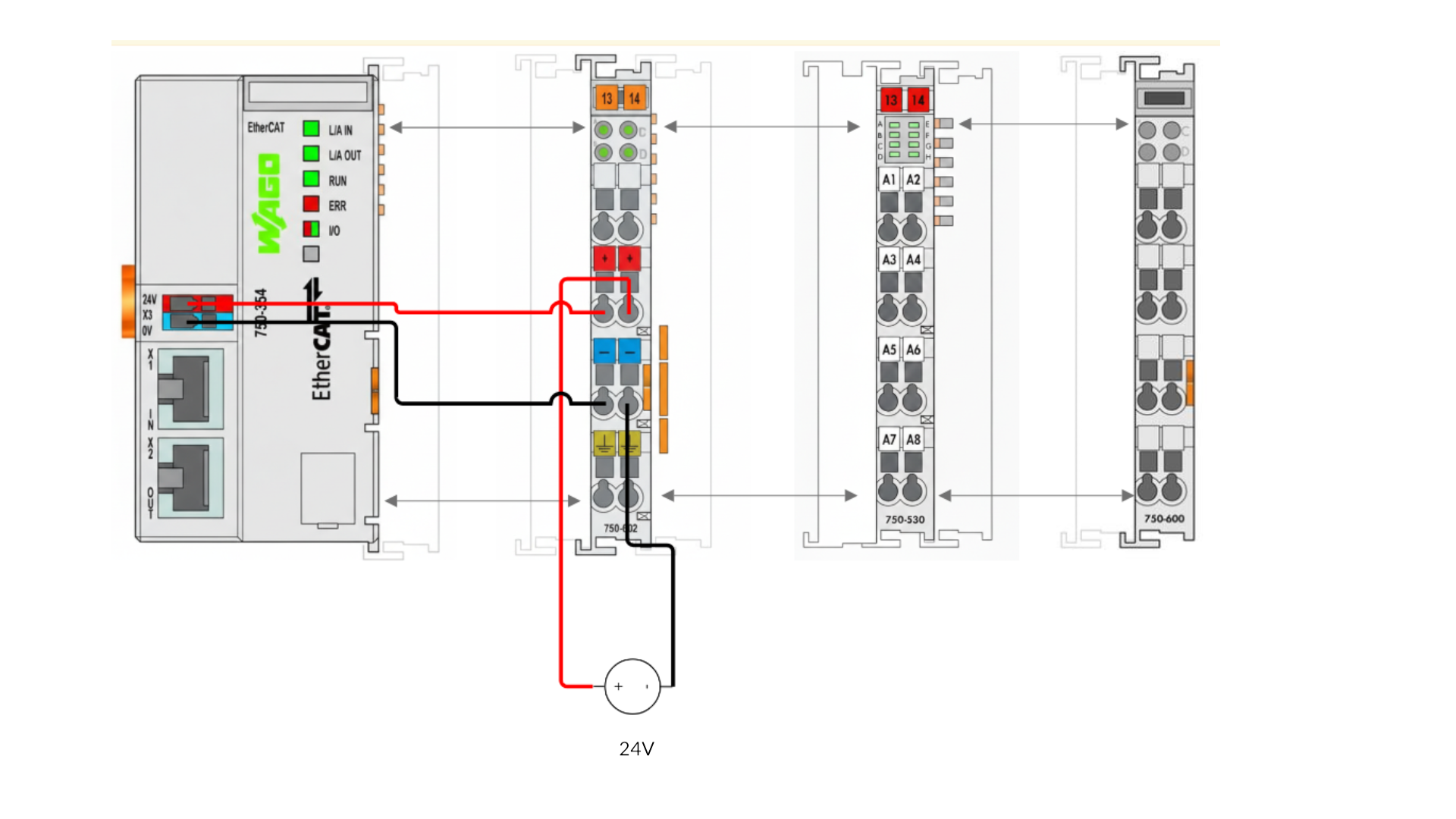
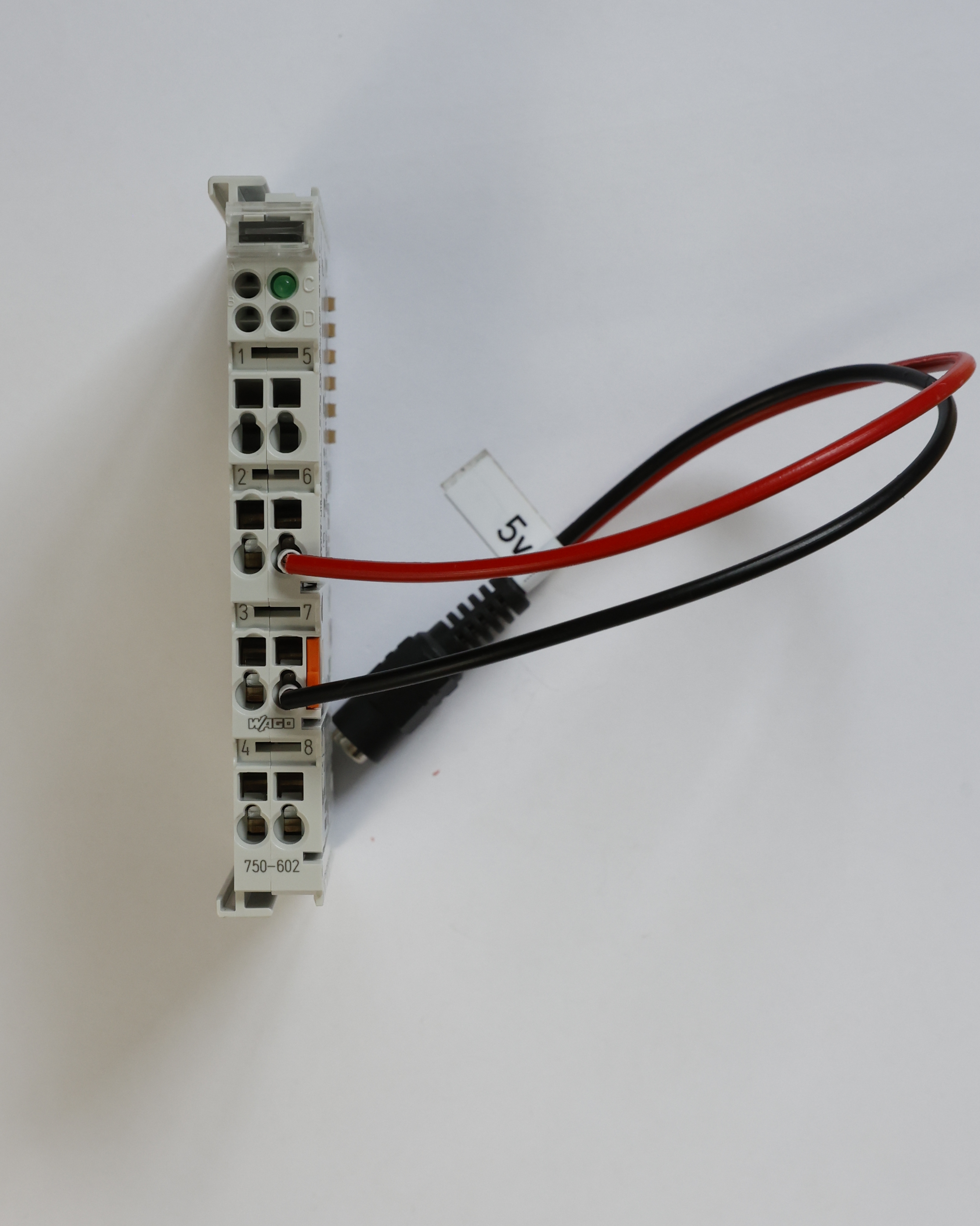
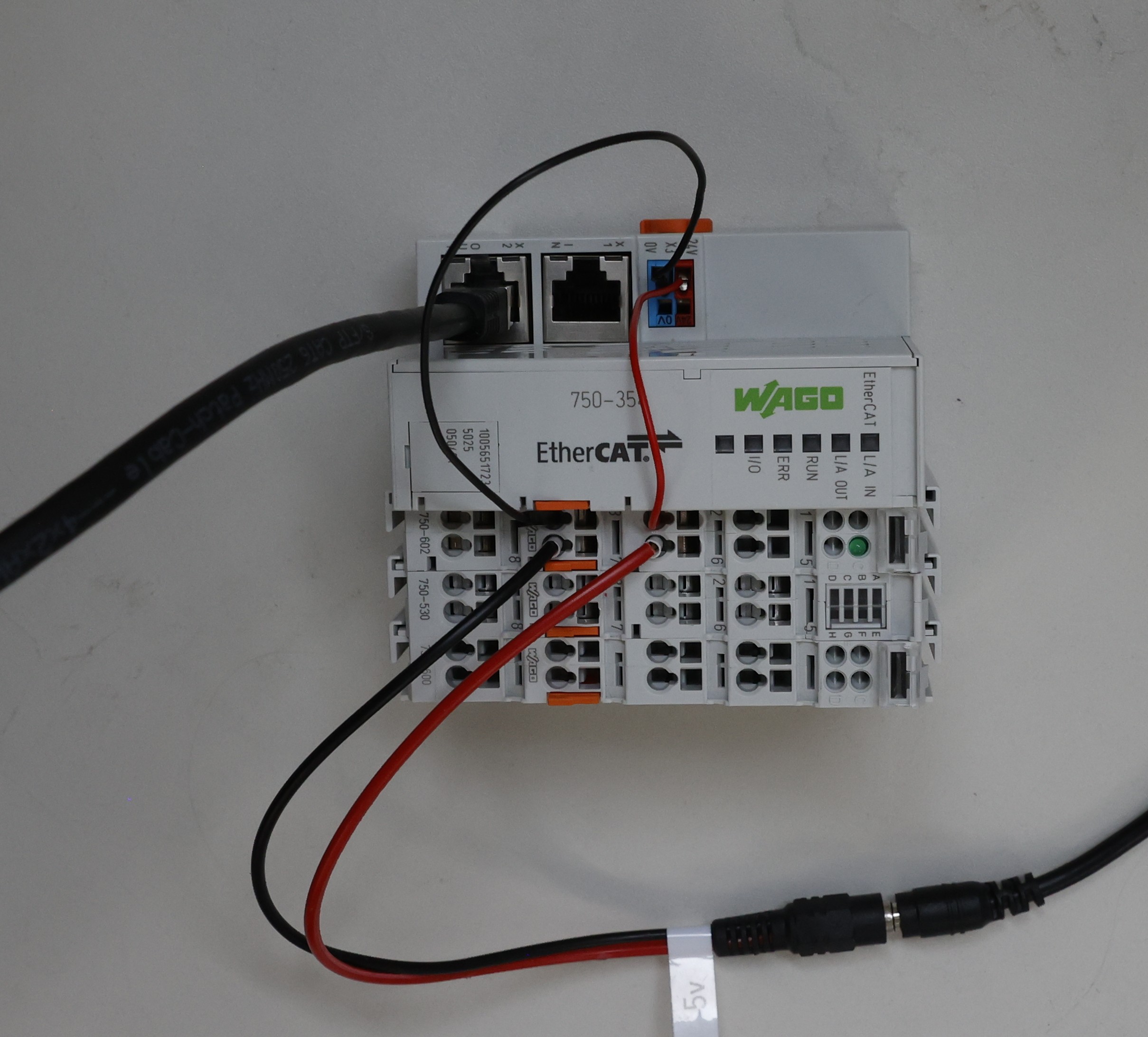
The 750-602 EtherCAT Power Terminal requires 24V DC.
In this example, a standard 24V AC/DC adapter with a hollow plug is used.
Perform the following wiring on the 750-530:
- Hollow plug red wire (+24 V) → Terminal 6
- Hollow plug black wire (0 V) → Terminal 7
Slide the 750-602 EtherCAT Power Terminal onto the right side of the 750-354 Coupler until it locks.
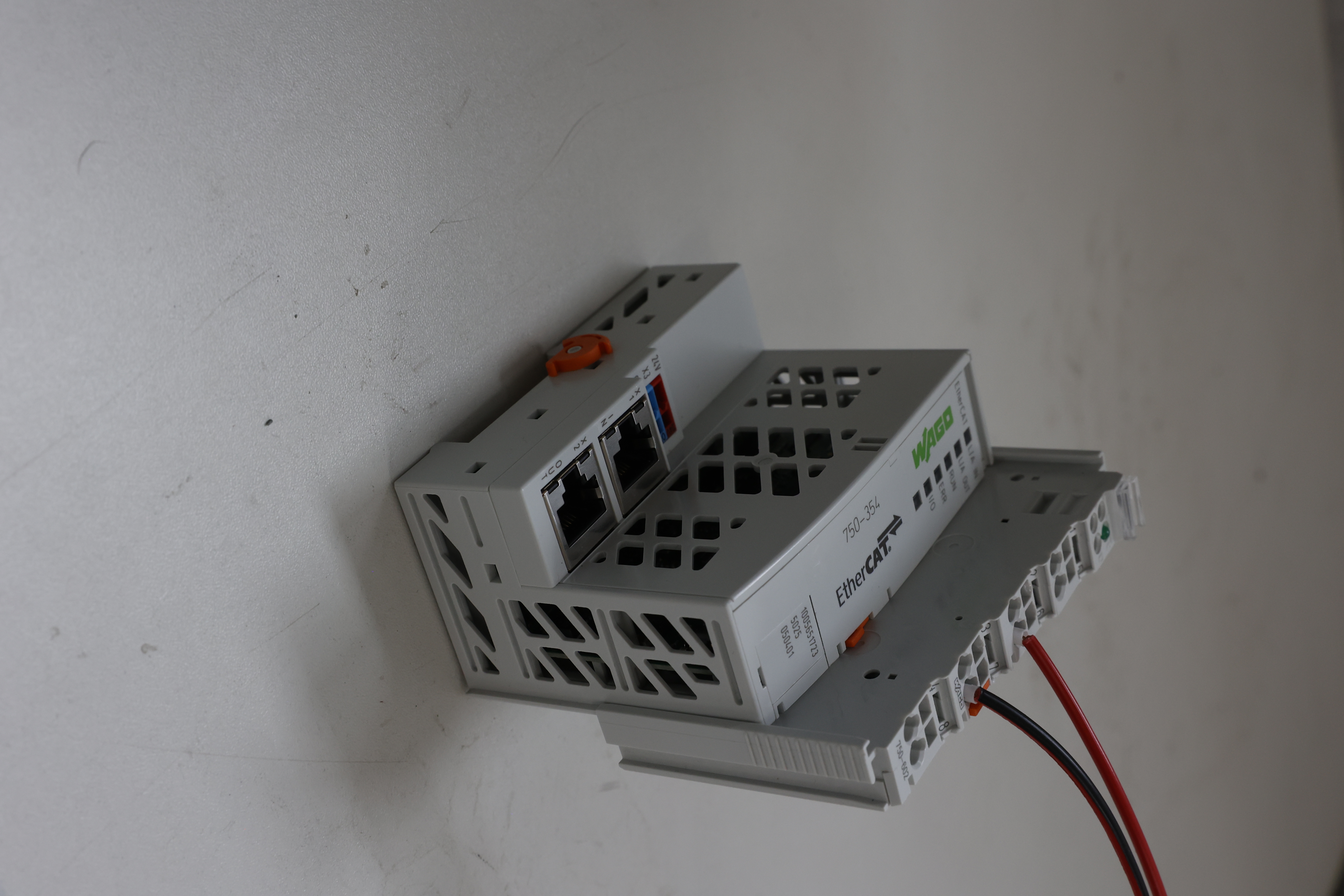
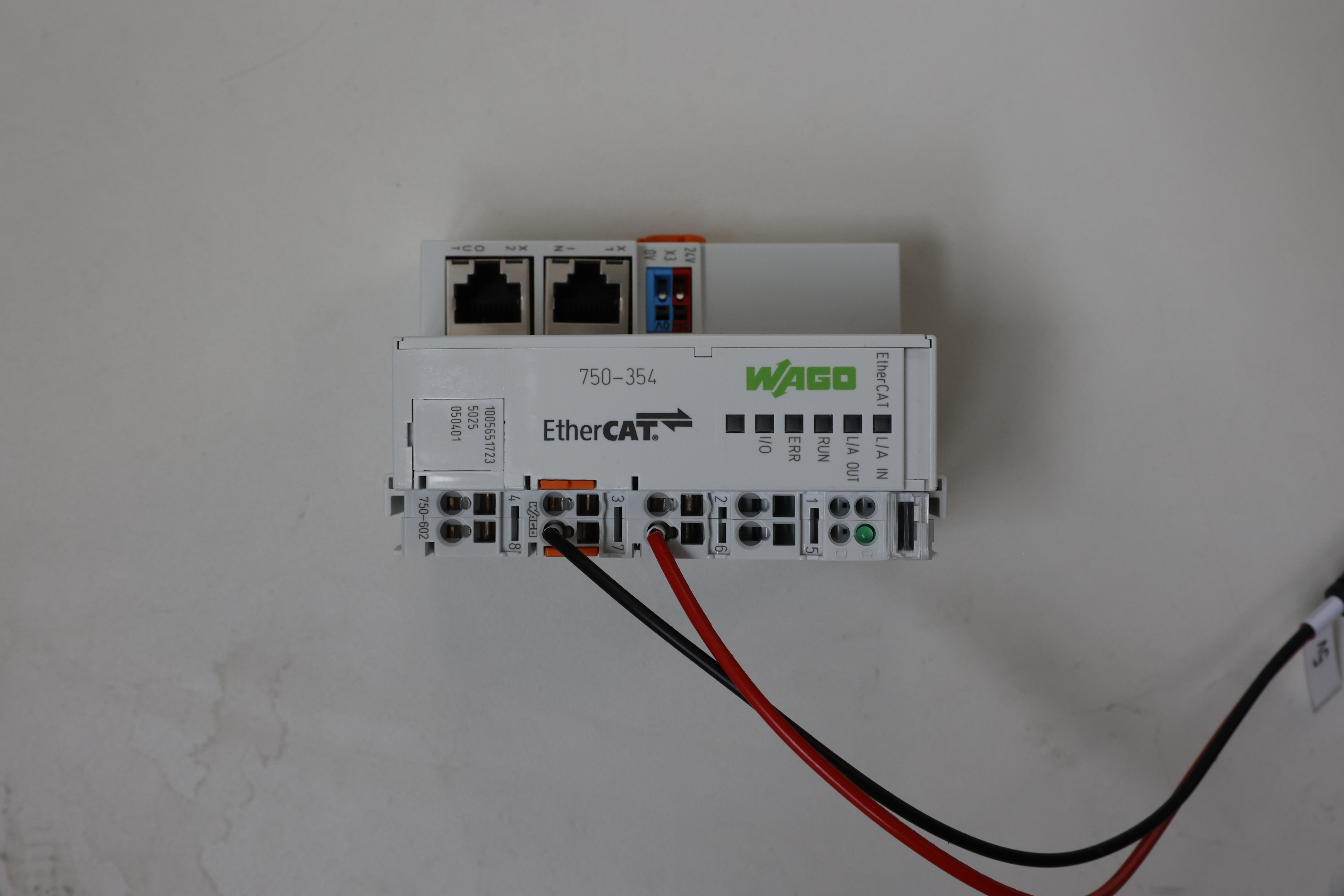
Perform the following wiring:
- Red wire Terminal 2 of 750-602 → Supply voltage port (+24 V) of the 750-354
- Black wire Terminal 3 of 750-602 → Supply voltage port (0 V) of the 750-354
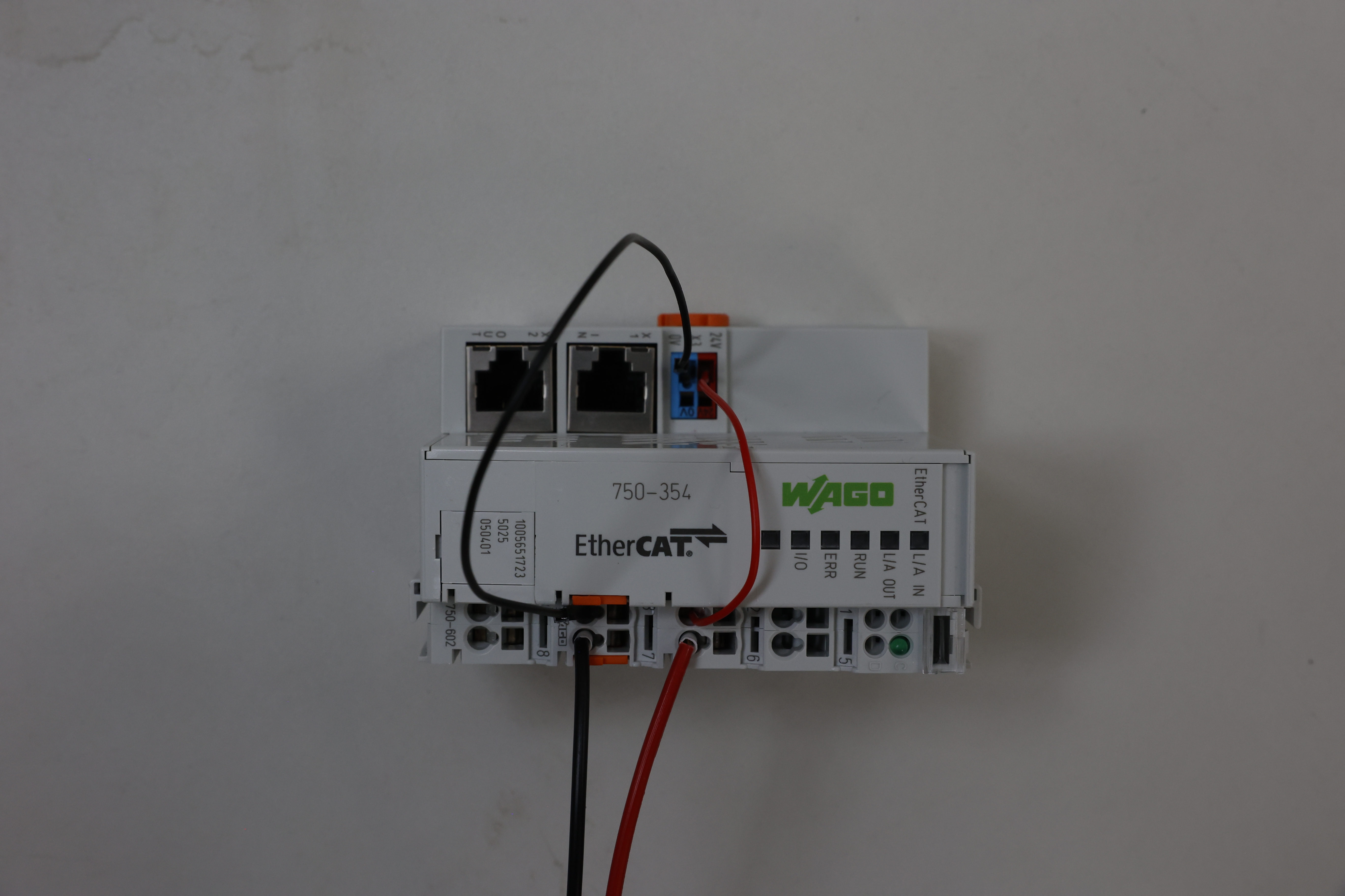
Slide the 750-530 EtherCAT Terminal onto the right side of the 750-602 until it locks.
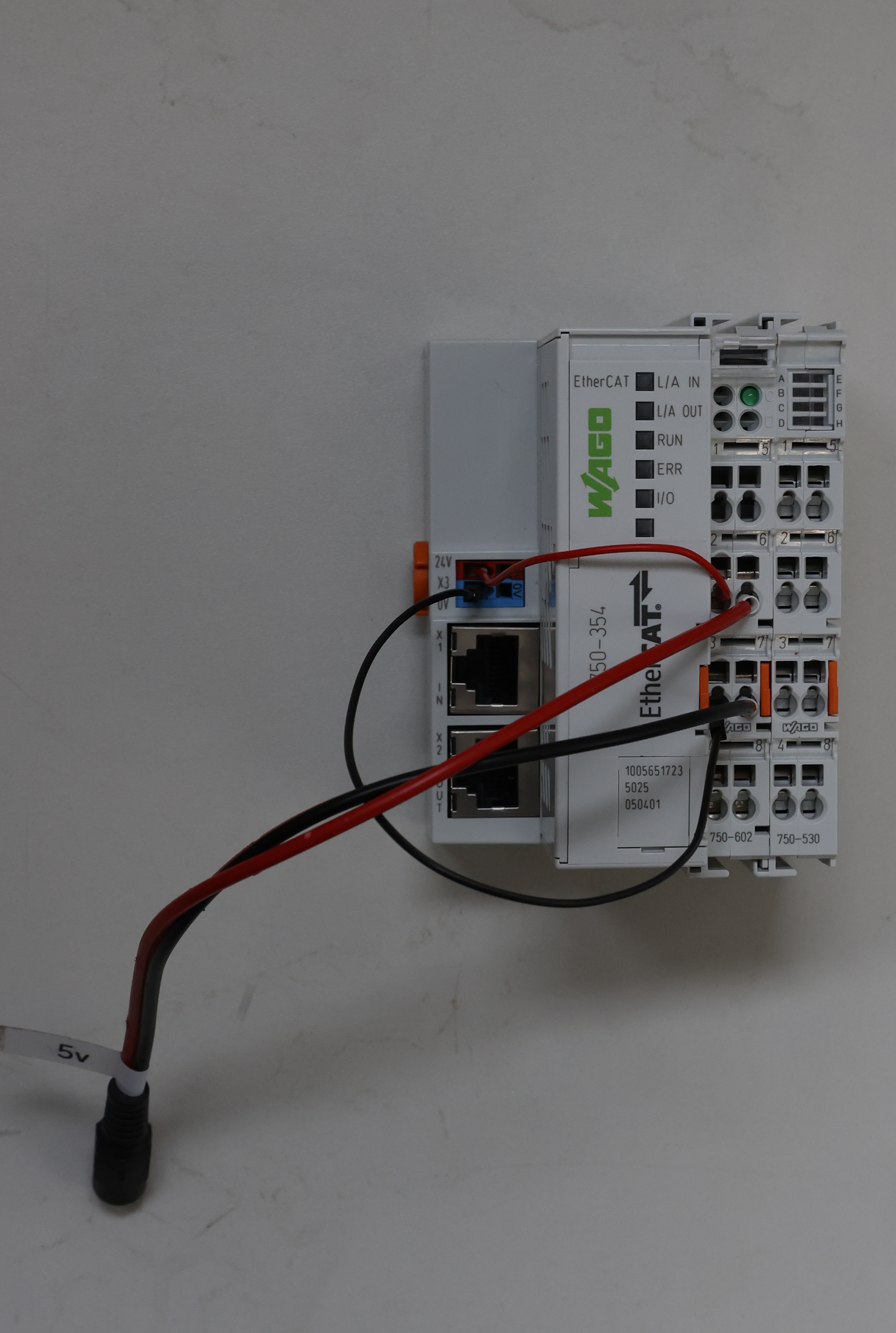
Slide the 750-600 End Module onto the right side of the 750-530 until it locks.
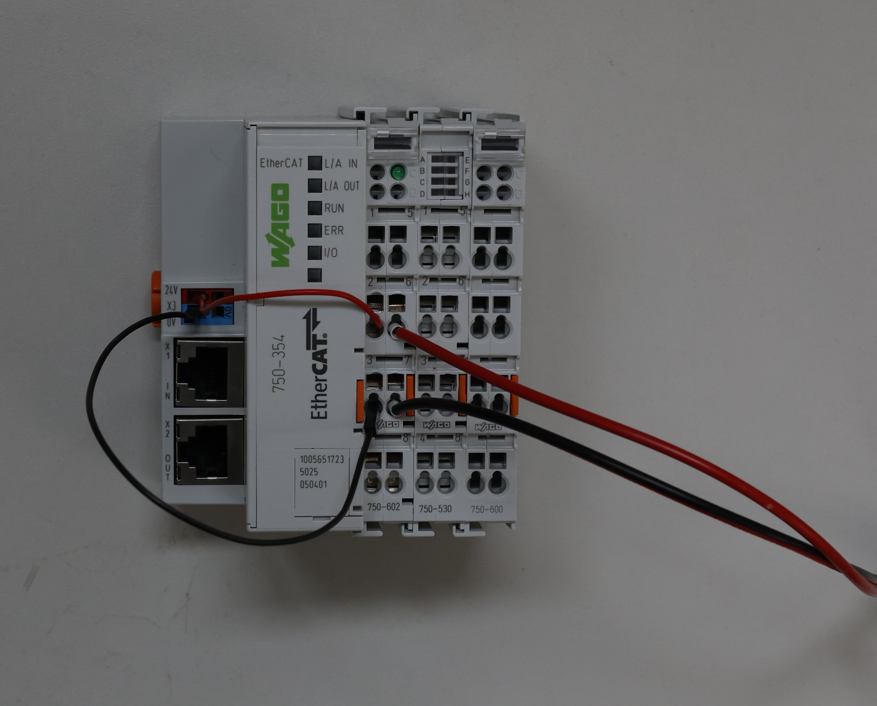
Connect the 24V AC/DC adapter to the hollow plug installed earlier.
Connect your PC to the INPUT port of the 750-354 Coupler.
See Device Example Basics to install and run the software, then return here for the device-specific demo steps.
After backend and frontend are running, open the EtherCAT tab.
You should see:
- WAGO 750-354 (Coupler)
- WAGO 750-530 (Digital Output Terminal)
For both devices:
- Click Assign
- Select Wago DO Test V1
- Enter a serial number
- Must not be 0
- Must be the same for both devices
- Click Write
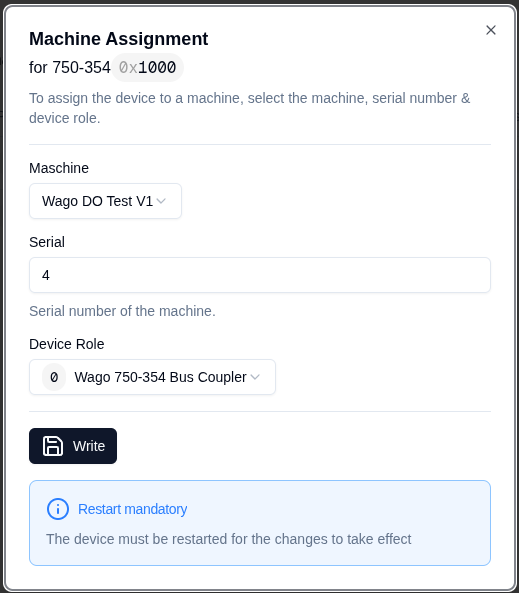
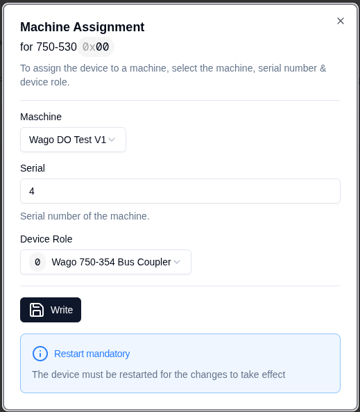
Restart the backend.
In the vertical navigation bar, Wago DO Test should now appear. Click on it:
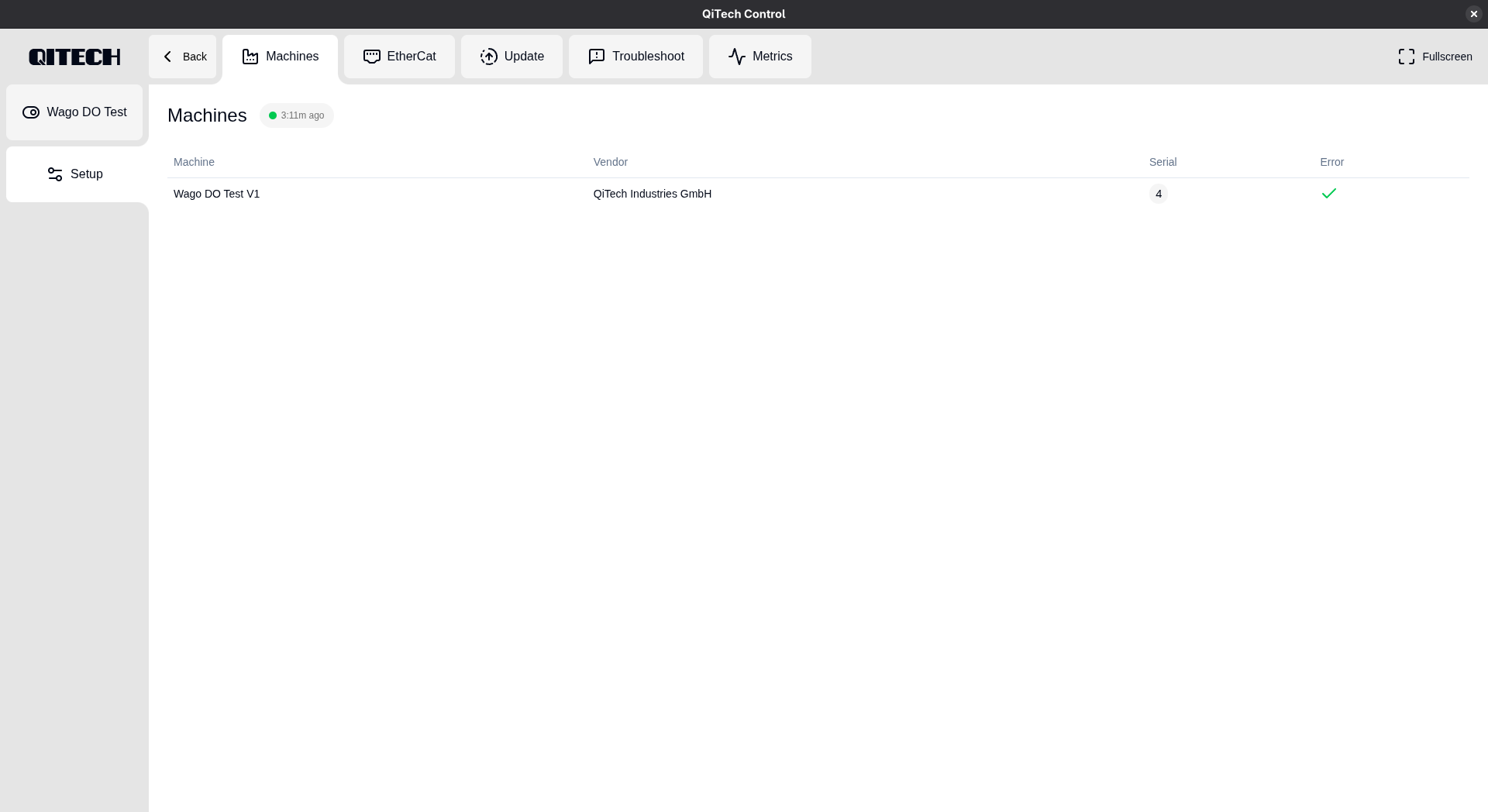
You can now toggle the eight outputs of the 750-530: