Minimal Example WAGO 750‐652
Complete Hardware + Software Walkthrough
Modern industrial PLC systems use distributed fieldbus I/O modules such as the WAGO 750-652 to interface with Motors or other Serial Devices. From a programming perspective, each channel corresponds to a control struct and input/output buffers.
The WAGO 750-652 provides one serial channel. Which can be used to:
- Control any Serial Device
- Read Sensor Data over serial
- Send Control signals to PC over serial
- Control an Inverter ...
This example demonstrates the simplest possible interaction: Sending a message in bytes over the serial connection, and displaying any message received.
- WAGO 750-652 (1-channel serial Terminal)
- WAGO 750-602 EtherCAT Power Terminal
- WAGO 750-354 EtherCAT Coupler
- WAGO 750-600 End Module
- 24 V DC power source (AC/DC adapter with 24 V output is sufficient)
- Connecting wires (0.5–1.5 mm² recommended)
- DC hollow plug
- Linux PC (Ubuntu/Debian recommended)
- Ethernet cable
- Flat-head screwdriver
See Device Example Basics for software prerequisites.
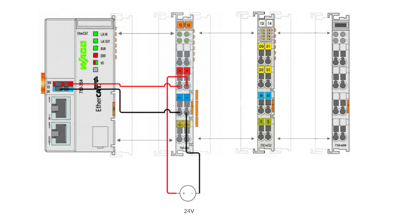
⚠️ Always disconnect power before wiring. See Device Example Basics for the safe wiring procedure.
The 750-602 EtherCAT Power Terminal requires 24V DC.
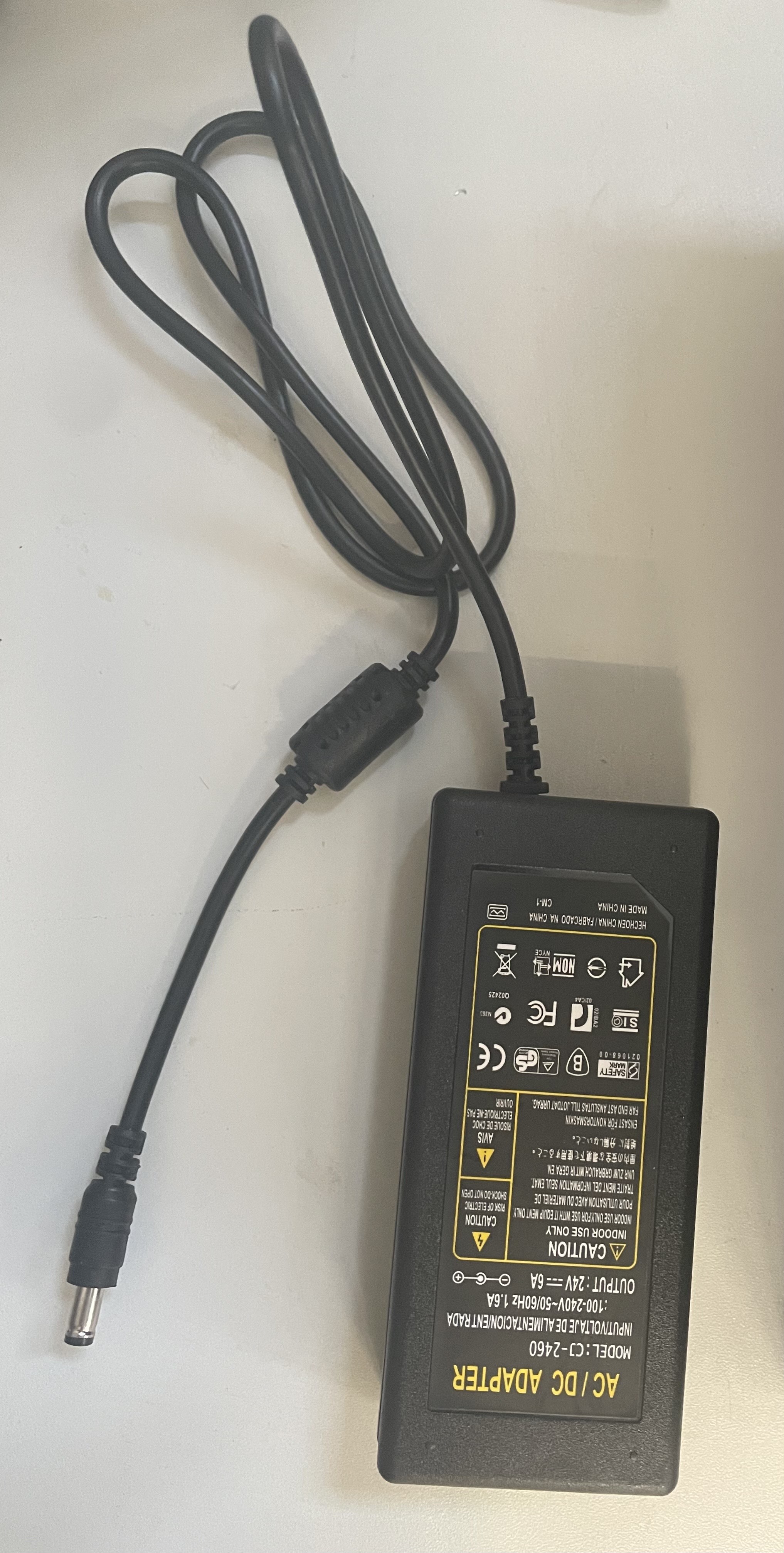
In this example, a standard 24V AC/DC adapter with a hollow plug is used.
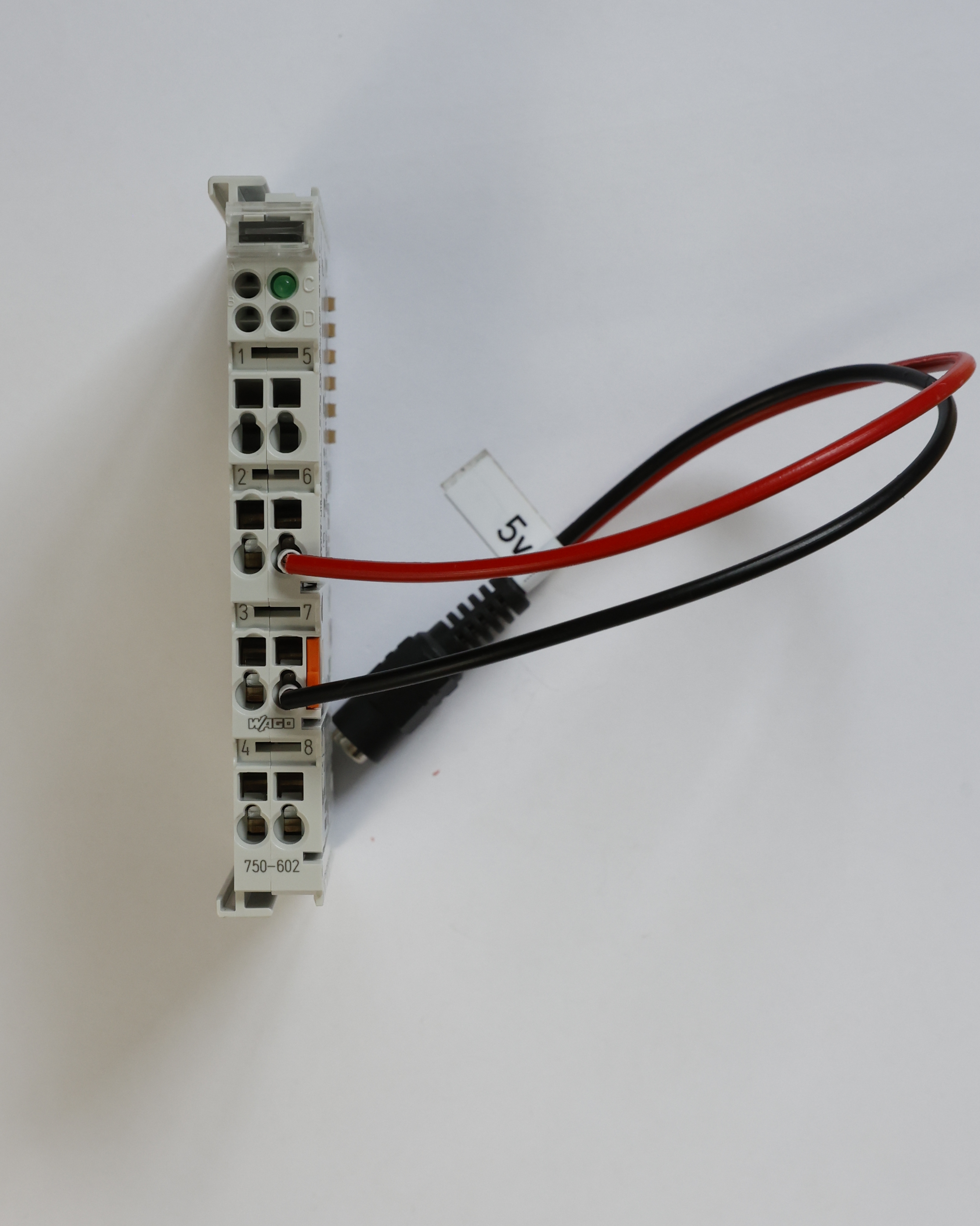
Perform the following wiring on the 750-652:
- Hollow plug red wire (+24 V) → Terminal 6
- Hollow plug black wire (0 V) → Terminal 7
Slide the 750-602 EtherCAT Power Terminal onto the right side of the 750-354 Coupler until it locks.
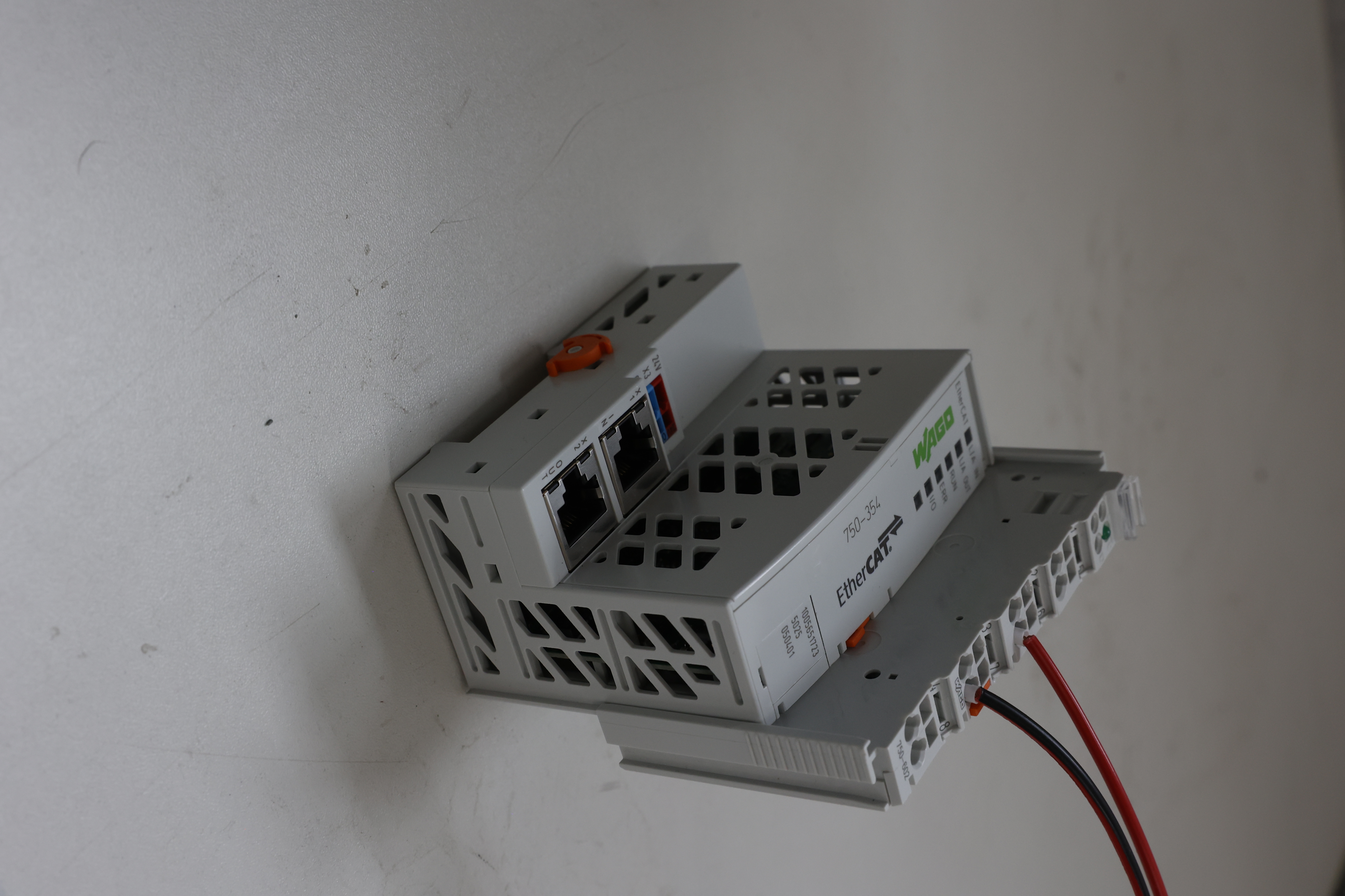
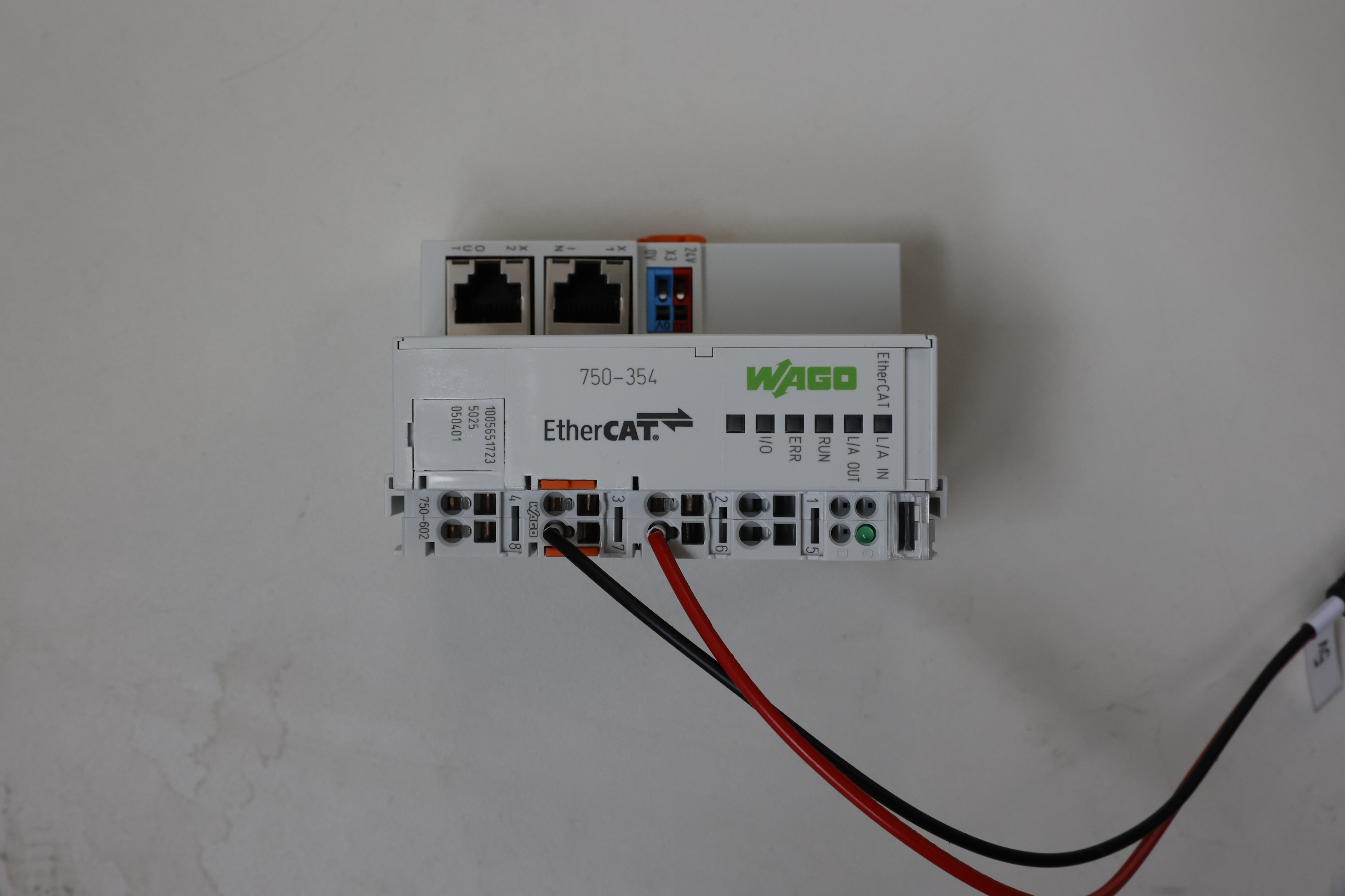
Perform the following wiring:
- Red wire Terminal 2 of 750-602 → Supply voltage port (+24 V) of the 750-354
- Black wire Terminal 3 of 750-602 → Supply voltage port (0 V) of the 750-354
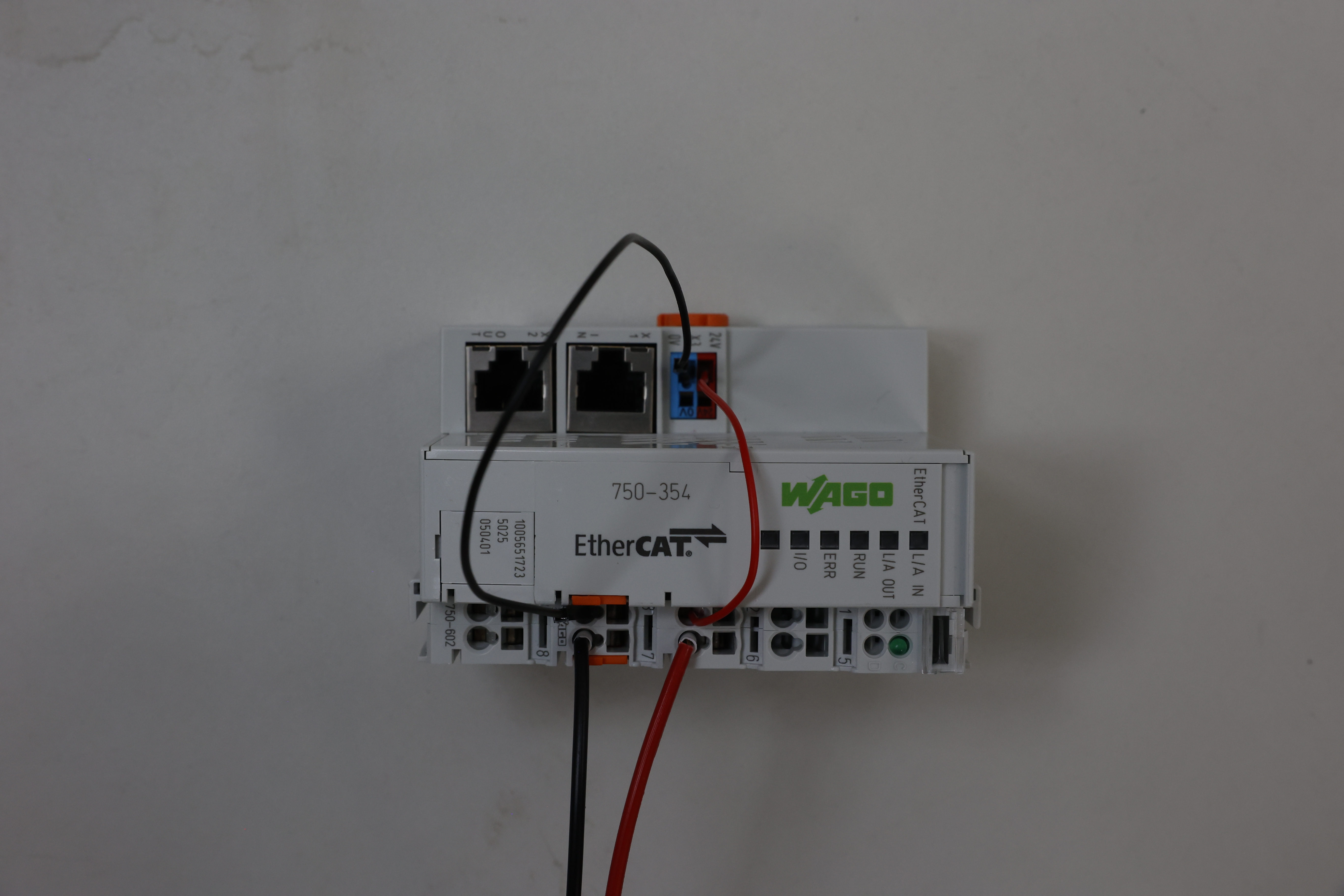
Slide the 750-652 EtherCAT Terminal onto the right side of the 750-602 until it locks.
Slide the 750-600 End Module onto the right side of the 750-652 until it locks.
Connect the 24V AC/DC adapter to the hollow plug installed earlier.
Connect your PC to the INPUT port of the 750-354 Coupler.
See Device Example Basics to install and run the software, then return here for the device-specific steps.
In the case of most "complex" Wago I/O Terminals with configuration it is handled through Wago I/O Check.
For Demonstration purposes we configure 48 byte process image, rs485 half-duplex, a baudrate of 19200bps, 8 data-bits, 1 stop-bits and no parity:

If you wish to communicate with the serial terminal, then these settings have to match the settings the communication partner has.
After backend and frontend are running, open the EtherCAT tab.
You should see:
- WAGO 750-354 (Coupler)
- WAGO 750-652 Serial Terminal
For both devices:
- Click Assign
- Select Wago Serial V1
- Enter a serial number
- Must not be 0
- Must be the same for both devices
- Click Write
Restart the backend.
In the vertical navigation bar, Wago Serial Test should now appear. Click on it:

You can send a message of up to 22 character length by typing into the input field and pressing send.
Here you can also see any data received by the serial terminal:

To send and receive you can use any program you wish. In this example we have used putty as it is an easy to use program for something like this. After configuring the settings and pressing Open, a Terminal Window opens in which you can type to send data and in which you also receive the message of the 750-652:
