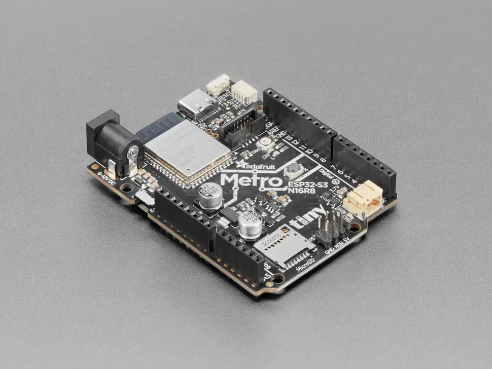
Adafruit Metro ESP32 S3
- OpenDeck target name:
metro_esp32s3 - Power: USB C
- MCU: ESP32-S3
- MIDI: USB, DIN
- OSC: No
- Traffic indicators: 2
- Digital inputs: 12
- Outputs: 5 (PWM / level control)
- Analog inputs: 0
- Board docs: Adafruit Metro ESP32-S3
- Buy links:
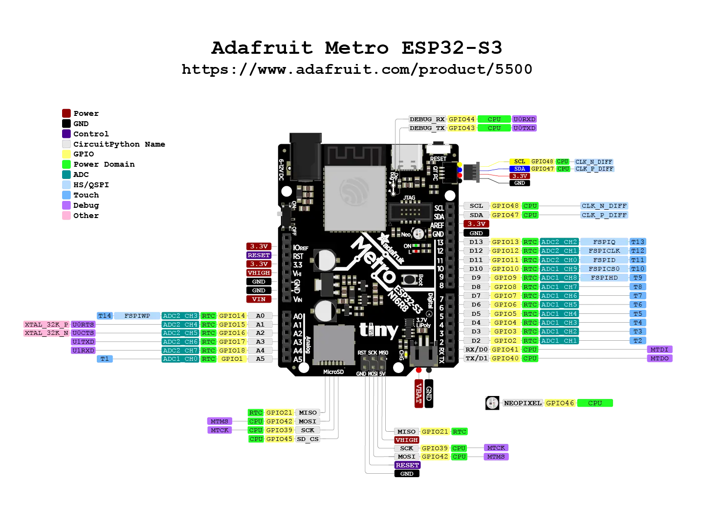
Pinout to use as an reference to pins in later sections:
| Switch # | Pin 1 | Pin 2 |
|---|---|---|
| 0 | GPIO2 | GND |
| 1 | GPIO3 | GND |
| 2 | GPIO4 | GND |
| 3 | GPIO5 | GND |
| 4 | GPIO6 | GND |
| 5 | GPIO7 | GND |
| 6 | GPIO14 | GND |
| 7 | GPIO15 | GND |
| 8 | GPIO16 | GND |
| 9 | GPIO17 | GND |
| 10 | GPIO18 | GND |
| 11 | GPIO1 | GND |
| Encoder # | Pin 1 | Pin 2 | Pin 3 |
|---|---|---|---|
| 0 | GPIO2 | GND | GPIO3 |
| 1 | GPIO4 | GND | GPIO5 |
| 2 | GPIO6 | GND | GPIO7 |
| 3 | GPIO14 | GND | GPIO15 |
| 4 | GPIO16 | GND | GPIO17 |
| 5 | GPIO18 | GND | GPIO1 |
Analog inputs are not enabled on this target.
Analog inputs are not enabled on this target.
Note: current-limiting resistors for LEDs are required in order to avoid damage to the board.
| Output # | Anode | Cathode |
|---|---|---|
| 0 | GPIO8 | GND |
| 1 | GPIO9 | GND |
| 2 | GPIO10 | GND |
| 3 | GPIO11 | GND |
| 4 | GPIO12 | GND |
| Indicator | LED |
|---|---|
| USB input | GPIO13 |
| USB output | GPIO13 |
| DIN input | GPIO13 |
| DIN output | GPIO13 |
Use the STEMMA QT connector for I2C.
| Signal | Pin |
|---|---|
| Vcc | 3V |
| GND | GND |
| SDA | GPIO47 |
| SCL | GPIO48 |
This board doesn't have DIN MIDI connectors, so they have to be added to the board with the corresponding circuitry. Use this schematic:

| MIDI In | MIDI out |
|---|---|
| GPIO41 | GPIO40 |
| Screen | Pin |
|---|---|
| Vcc | 5V |
| GND | GND |
| Rx | GPIO40 |
| Tx | GPIO41 |
Hold OpenDeck switch 0 / GPIO2 low while resetting or powering the board to
enter the OpenDeck bootloader.
To flash this board with the OpenDeck firmware, go to the OpenDeck configurator and follow the instructions.
DIN MIDI and touchscreen use the same UART pins on this board, so only one of them can be enabled at a time.