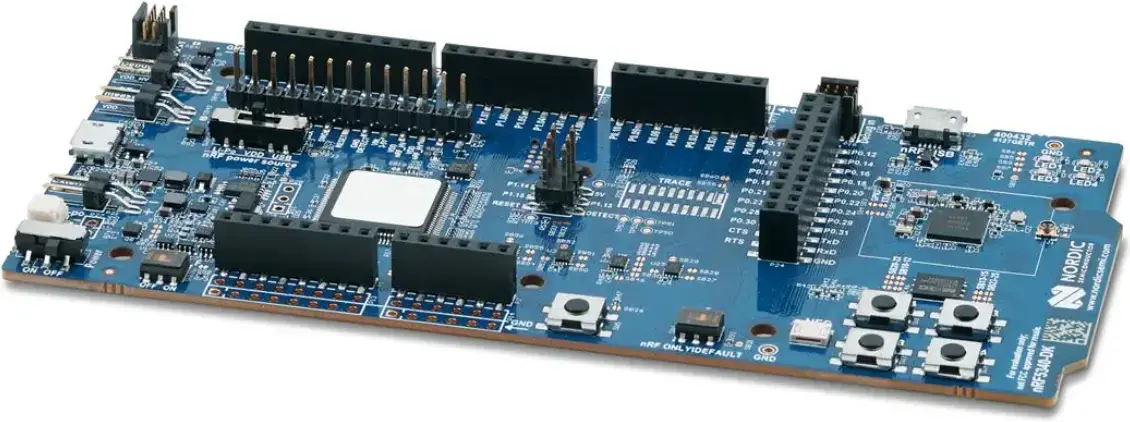
nRF5340 DK
- OpenDeck target name:
nrf5340dk - Power: USB
- MCU: nRF5340
- MIDI: USB, DIN, BLE
- OSC: No
- Traffic indicators: 6
- Digital inputs: 12
- Outputs: 4 (PWM / level control)
- Analog inputs: 6
- Board docs: nRF5340 DK
- Buy links:
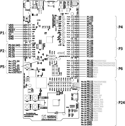
Pinout to use as an reference to pins in later sections:
| Switch # | Pin 1 | Pin 2 |
|---|---|---|
| 0 | Button 1 / P0.23 | GND |
| 1 | Button 2 / P0.24 | GND |
| 2 | Button 3 / P0.08 | GND |
| 3 | Button 4 / P0.09 | GND |
| 4 | P1.04 | GND |
| 5 | P1.05 | GND |
| 6 | P1.06 | GND |
| 7 | P1.07 | GND |
| 8 | P1.08 | GND |
| 9 | P1.09 | GND |
| 10 | P1.10 | GND |
| 11 | P1.11 | GND |
| Switch # | Pin 1 | Pin 1 | Pin 2 |
|---|---|---|---|
| 12 | P0.04 | GND with 10k resistor | 3V |
| 13 | P0.05 | GND with 10k resistor | 3V |
| 14 | P0.06 | GND with 10k resistor | 3V |
| 15 | P0.07 | GND with 10k resistor | 3V |
| 16 | P0.25 | GND with 10k resistor | 3V |
| 17 | P0.26 | GND with 10k resistor | 3V |
| Encoder # | Pin 1 | Pin 2 | Pin 3 |
|---|---|---|---|
| 0 | Button 1 / P0.23 | GND | Button 2 / P0.24 |
| 1 | Button 3 / P0.08 | GND | Button 4 / P0.09 |
| 2 | P1.04 | GND | P1.05 |
| 3 | P1.06 | GND | P1.07 |
| 4 | P1.08 | GND | P1.09 |
| 5 | P1.10 | GND | P1.11 |
| Potentiometer # | Pin 1 | Pin 2 | Pin 3 |
|---|---|---|---|
| 0 | 3V | P0.04 | GND |
| 1 | 3V | P0.05 | GND |
| 2 | 3V | P0.06 | GND |
| 3 | 3V | P0.07 | GND |
| 4 | 3V | P0.25 | GND |
| 5 | 3V | P0.26 | GND |
| FSR # | Pin 1 | Pin 2 | Pin 2 |
|---|---|---|---|
| 0 | 3V | P0.04 | GND with 1k resistor |
| 1 | 3V | P0.05 | GND with 1k resistor |
| 2 | 3V | P0.06 | GND with 1k resistor |
| 3 | 3V | P0.07 | GND with 1k resistor |
| 4 | 3V | P0.25 | GND with 1k resistor |
| 5 | 3V | P0.26 | GND with 1k resistor |
Note: current-limiting resistors for LEDs are required in order to avoid damage to the board.
| Output # | Anode | Cathode |
|---|---|---|
| 0 | P1.12 | GND |
| 1 | P1.13 | GND |
| 2 | P1.14 | GND |
| 3 | P1.15 | GND |
| Indicator | LED |
|---|---|
| USB input | LED1 / P0.28 |
| USB output | LED2 / P0.29 |
| DIN input | LED3 / P0.30 |
| DIN output | LED4 / P0.31 |
| BLE input | LED3 / P0.30 |
| BLE output | LED4 / P0.31 |
| Signal | Pin |
|---|---|
| Vcc | 3V |
| GND | GND |
| SDA | P1.02 |
| SCL | P1.03 |
This board doesn't have DIN MIDI connectors, so they have to be added to the board with the corresponding circuitry. Use this schematic:

| MIDI In | MIDI out |
|---|---|
| P1.00 | P1.01 |
| Screen | Pin |
|---|---|
| Vcc | 5V |
| GND | GND |
| Rx | P1.00 |
| Tx | P1.01 |
Hold OpenDeck switch 0 / P0.23 low while resetting or powering the board to
enter the OpenDeck bootloader.
To flash this board with the OpenDeck firmware, go to the OpenDeck configurator and follow the instructions.
DIN MIDI and touchscreen use the same UART pins on this board, so only one of them can be enabled at a time.