Repository navigation
Marine Board Overview
Home › Marine Board hardware › Marine Board
Sisu Marine Board: ESP32-S3 controller with 12 V input, field PWM output, relay, CAN, isolated inputs, two 4–20 mA loops, shunt monitor and USB-C.
Before you start: Physical access to the board; power off before wiring
- Marine Board › Power input (CN1) — 12 V battery in on CN1 (GND, +12V BAT) through reverse diode, fuse F1 (2 A), SMBJ18A TVS and filter; USB-C powers logic/programming only.
- Marine Board › Field PWM output (CN2) — Low-side PWM drive for the alternator field on CN2 (+12V BAT, PWM): MCP1407 gate driver → BUK762R4-60E MOSFET, VS-43CTQ100S freewheel, fused by F3 (10 A), ~10 A continuous (copper-limited).
- Marine Board › Isolated inputs (U13) — Opto-isolated ENBL and RPM inputs and the TMP1 1-Wire temperature probe on connector U13.
- Marine Board › Tank loops & battery shunt — Two 12 V 4–20 mA tank-sender loops (U5 LVL1, U6 LVL2) and a Kelvin sense input for a 400 A / 75 mV battery shunt (U4 SH−/SH+).
- Marine Board › CAN, relay & I²C — NMEA 2000 CAN on U7 (termination jumper JP1), SPDT relay contacts on U12 (common fused by F4 10 A), and a Qwiic-style I²C port CN3.
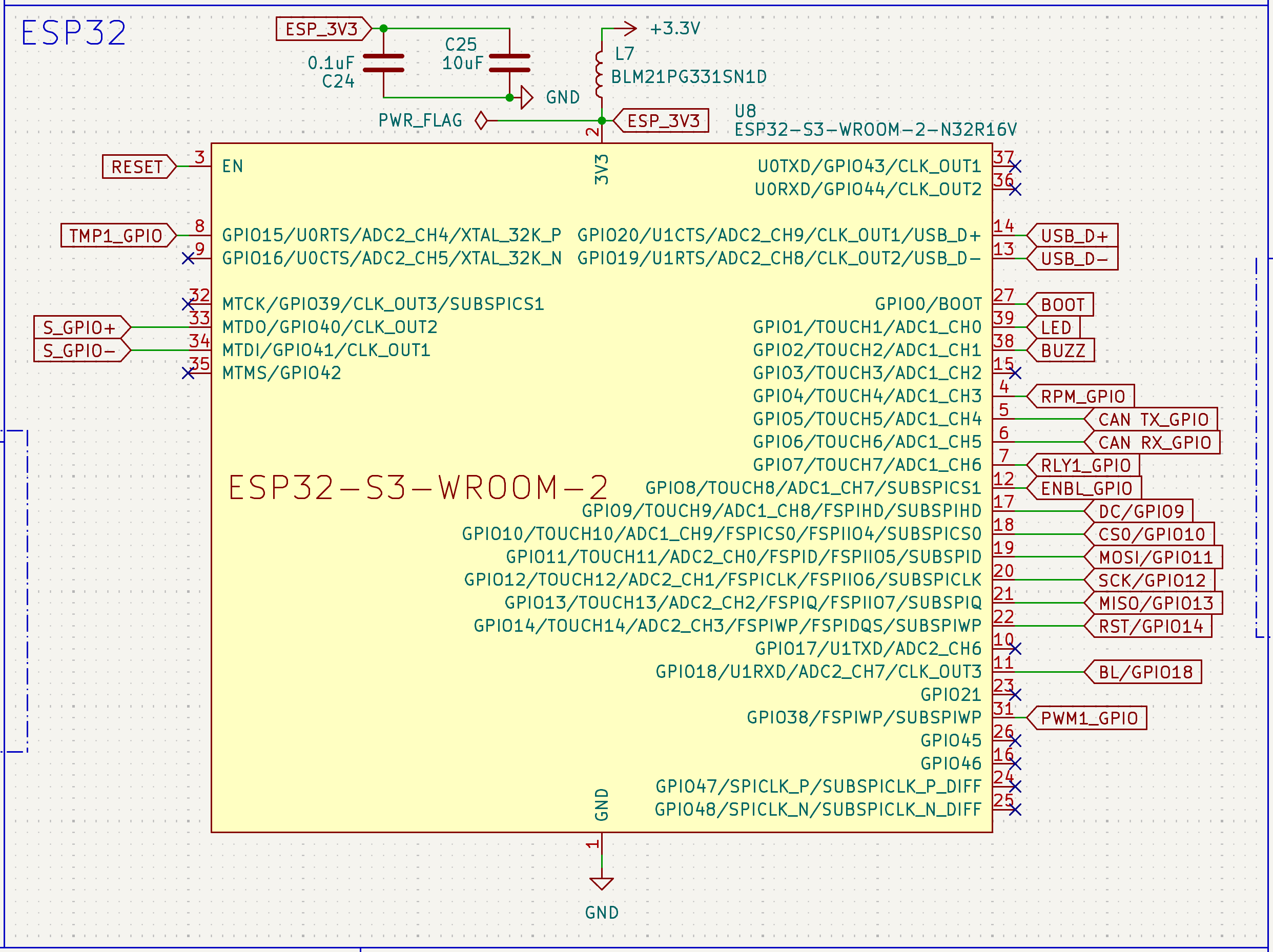
- Marine Board › Display header (CN4) — Connector CN4 (JST-GH 10-pin, vertical BM10B-GHS-TBT, top side; was U10 on v1.8) for an optional small SPI display: SCK/MOSI/MISO/CS on GPIO 12/11/13/10, DC GPIO9, RST GPIO14, backlight GPIO18, plus 3.3 V, 5 V and GND. No on-board I/O protection — internal short cable only.
- Marine Board › USB-C, Reset & Boot — USB-C (J1) for flashing, serial logs and 5 V logic power; Reset and Boot buttons for recovery.