Repository navigation
Features
Everything MyCAD can do, on one page. Every tool also has an article in the built-in help (Help at the bottom left, F1 over a tool, or search for it with Ctrl+K).
-
Liquid Glass: toolbar, browser, window buttons and panels float as glass above the model. A slider in Settings goes from Ultra Clear to Tinted.
-
Light, Dark, Automatic; Increase Contrast, Reduce Transparency, Reduce Motion.
-
English or German, with the terms of the German Fusion 360.
-
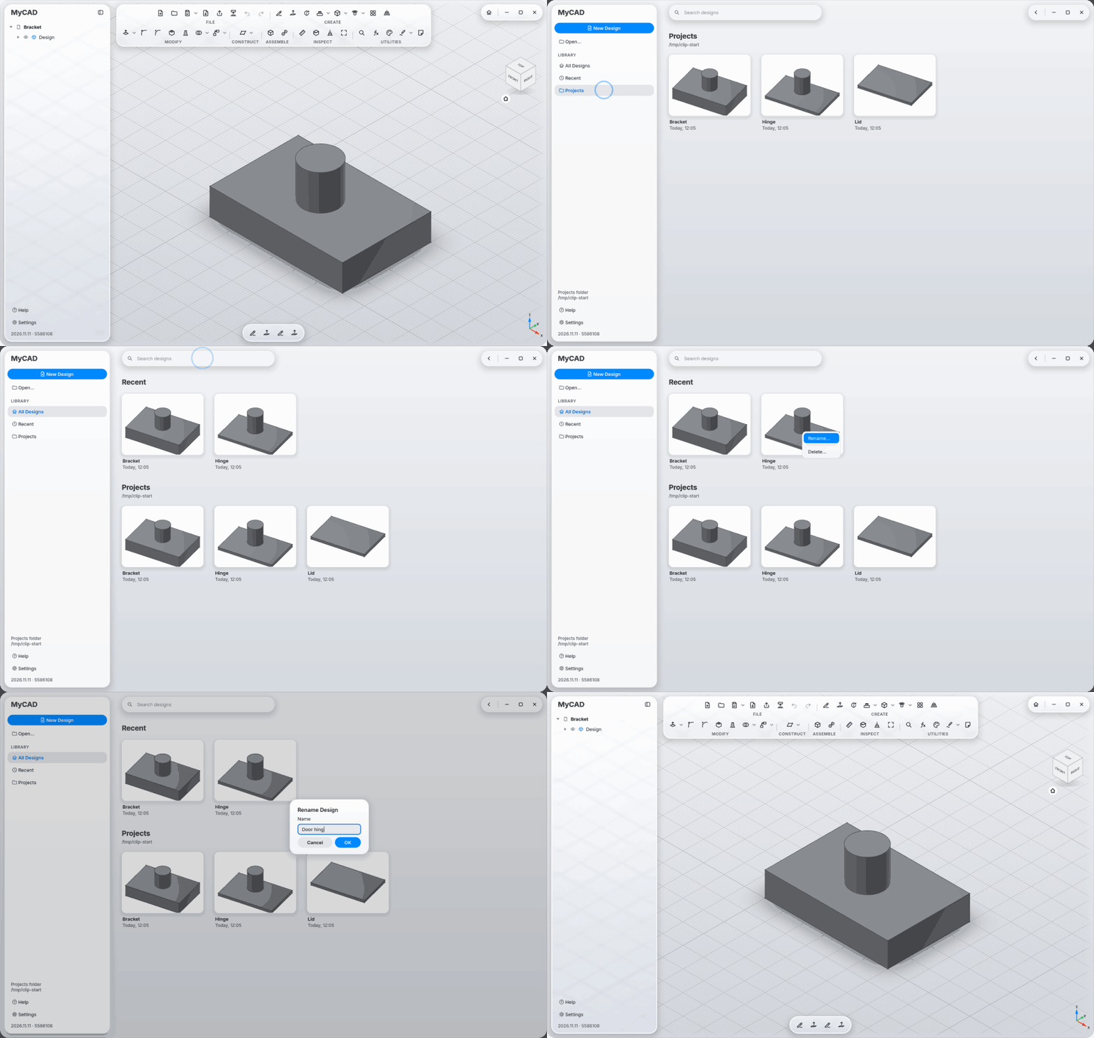
Start page with recent designs and your projects folder, large previews and search; right-click a design to rename or delete it.
-
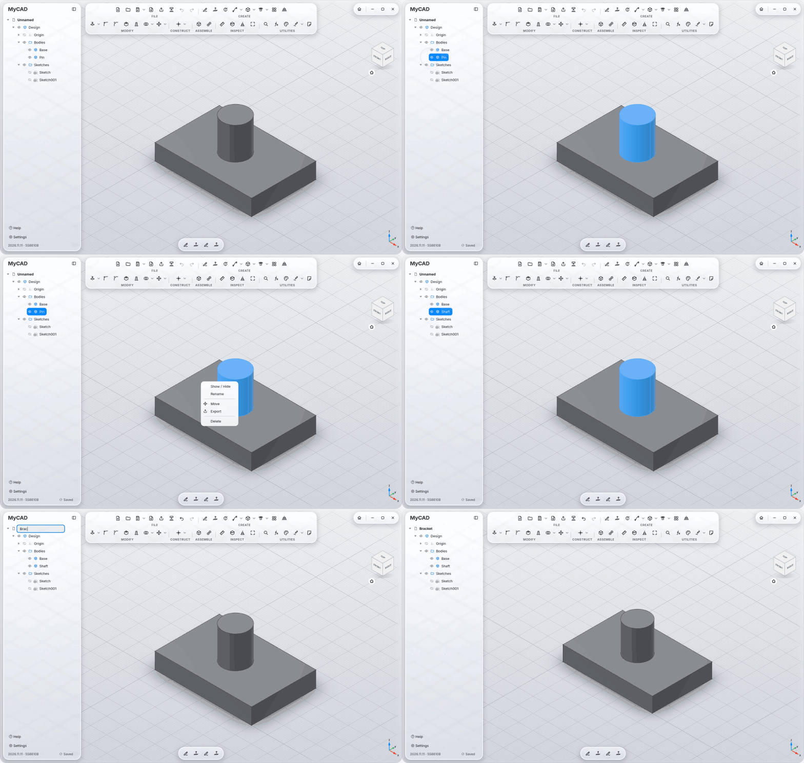
Browser with eye icons to show and hide, rename in place (F2), the design name renames the file too, and Saved at the bottom when everything is on disk.
-
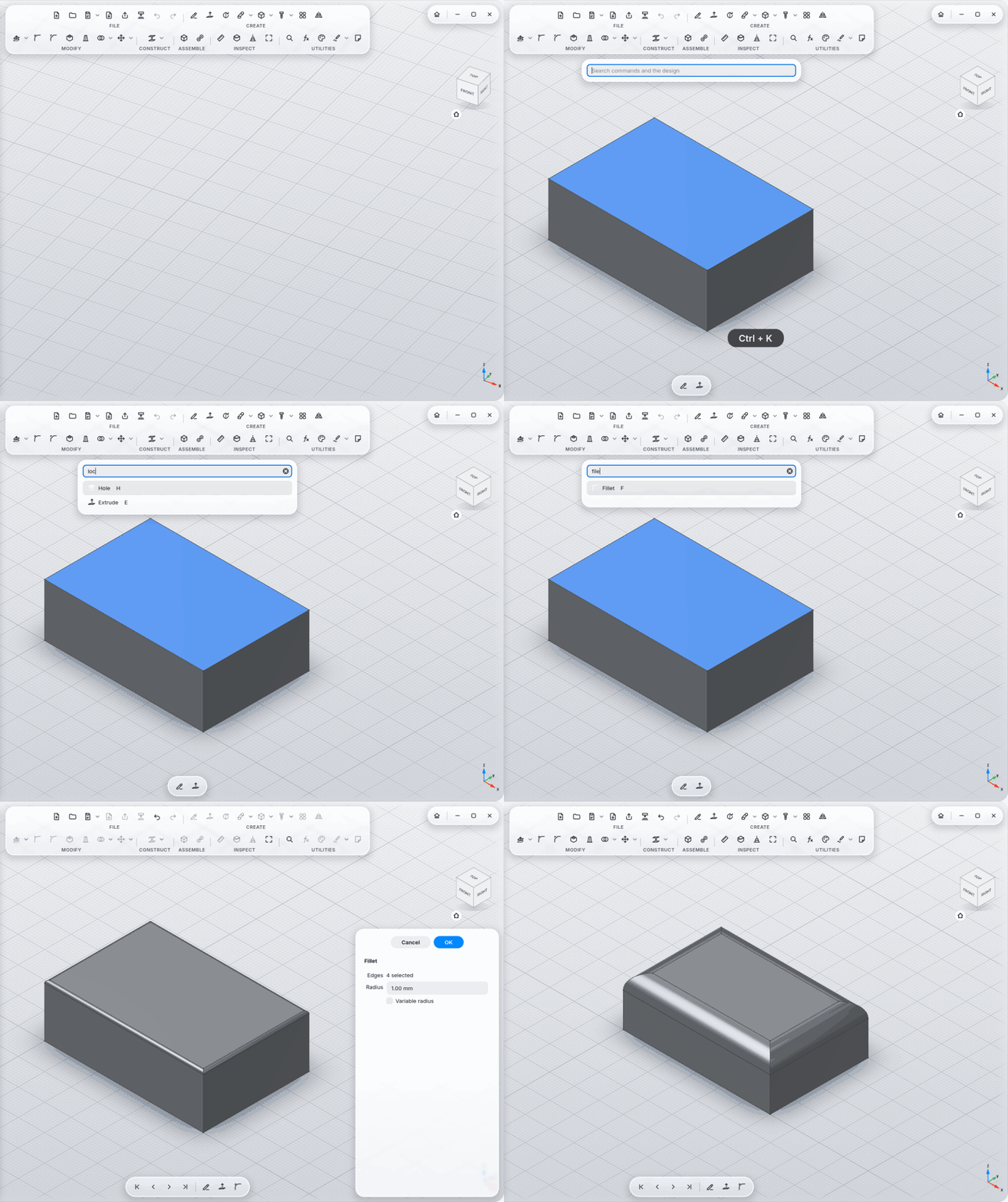
Command search with Ctrl+K: finds commands, bodies and sketches; forgives typos; understands English, German and words from other CAD programs (pad, pocket, push pull). The ones you used last are at the top.
-
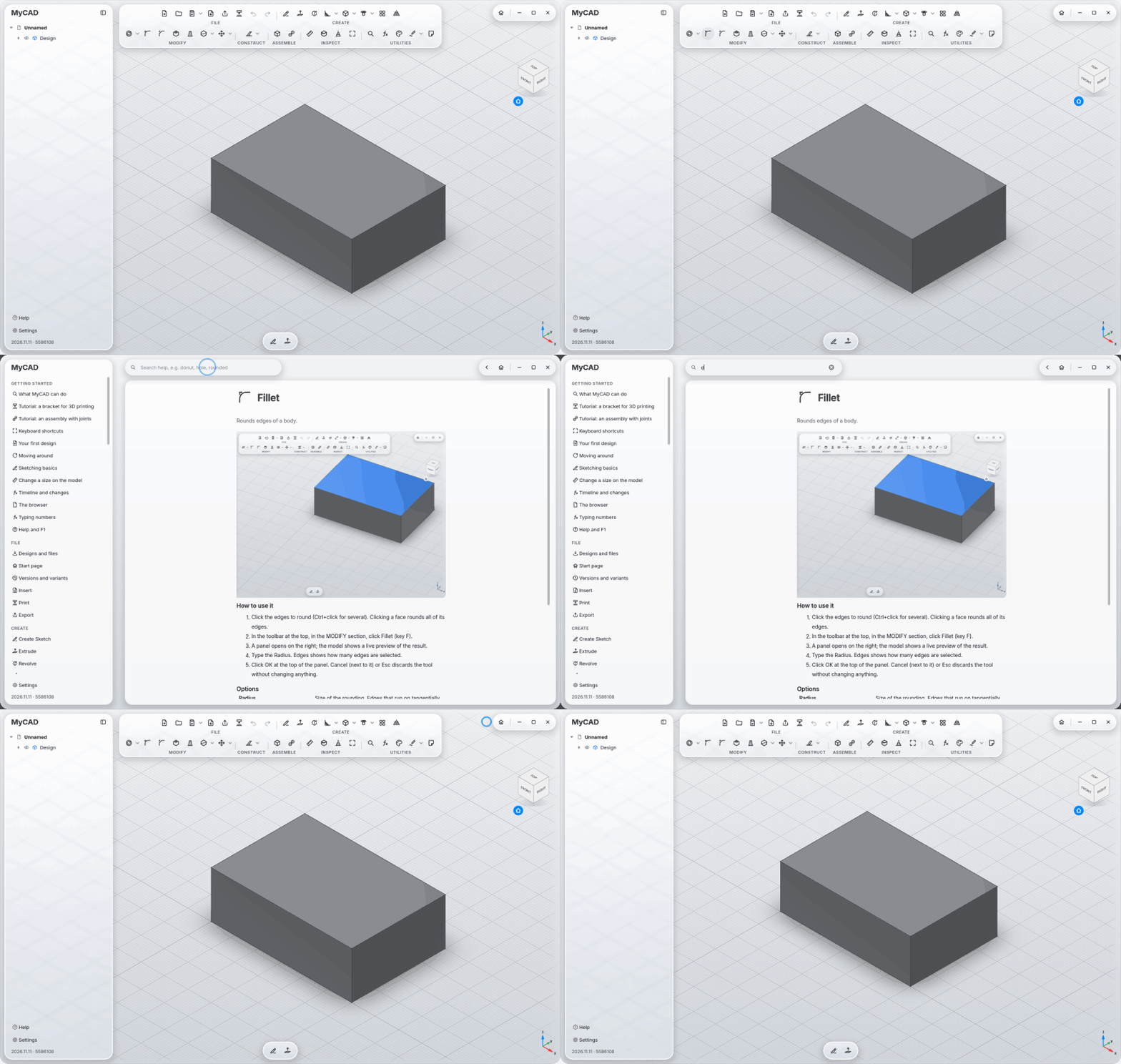
Built-in help with 95 articles, a clip for each, search, an overview and two tutorials; F1 opens the article for the tool under the mouse.
-
Draw: line, polyline, rectangle, circle, arc, slot, polygon, B-spline, conic, point, text; project model edges into the sketch.
-
Modify: fillet, trim, extend, split, offset, mirror, pattern, move, scale.
-
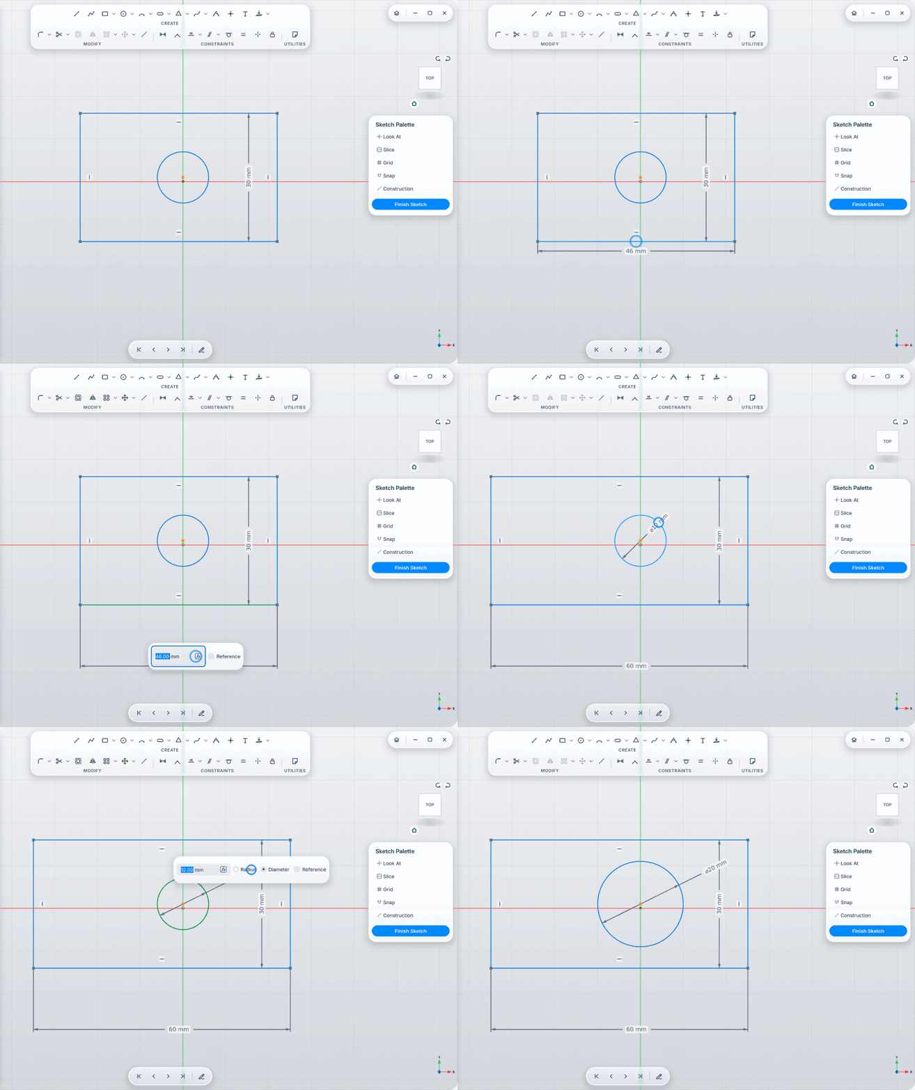
One Dimension tool that works out from the selection what to measure, typed right on the dimension (Tab jumps to the next one, no window); constraints coincident, horizontal, vertical, parallel, perpendicular, tangent, equal, symmetric, fix.
-
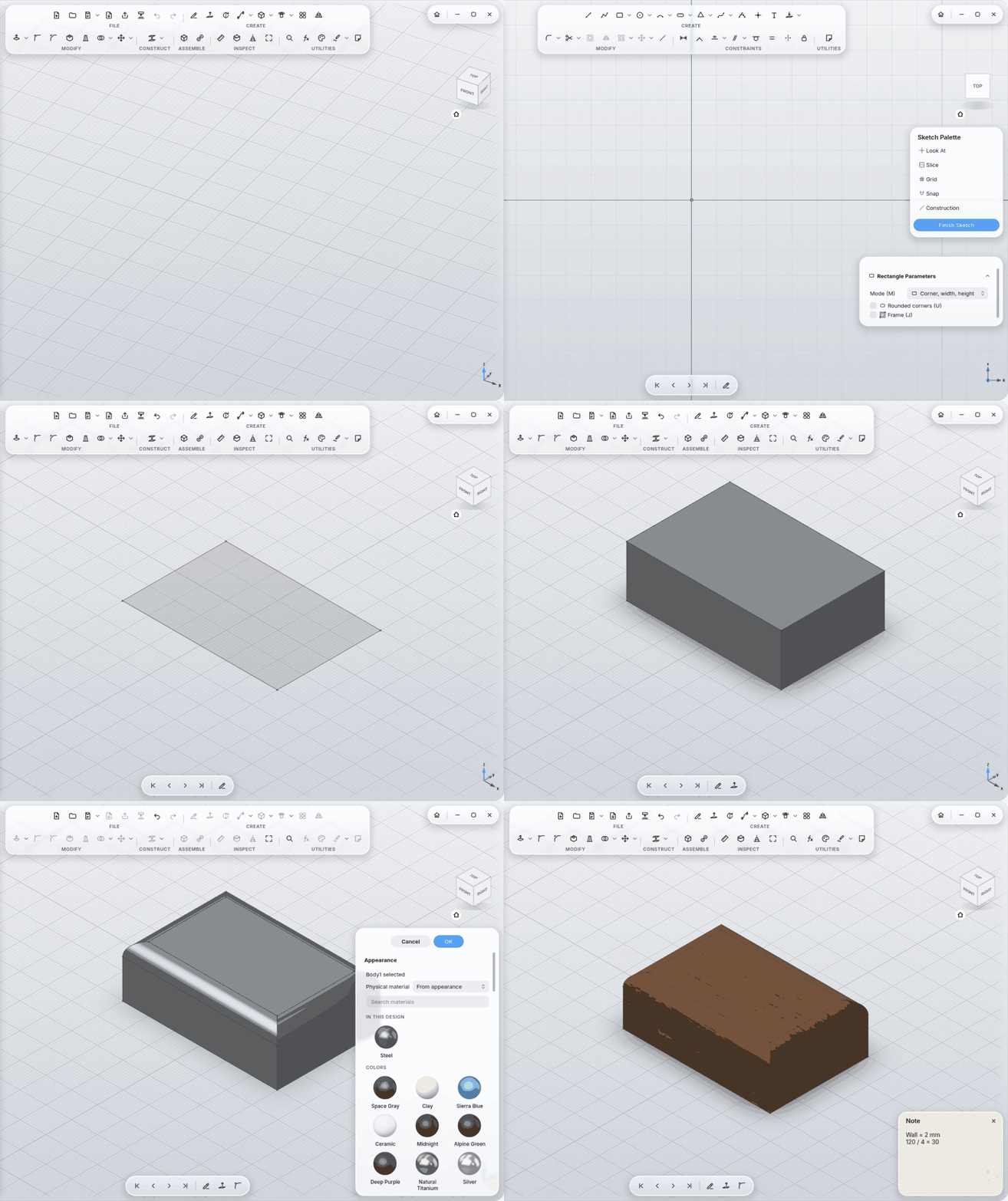
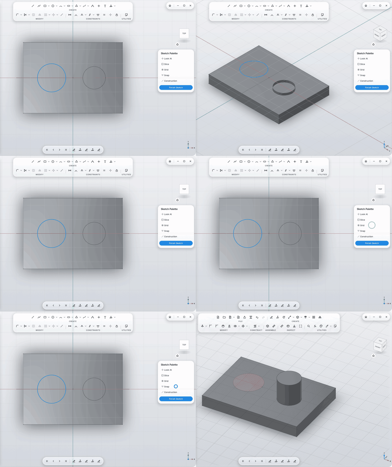
Sketch Palette: Look At, Slice (cut away what's in front of the sketch), Grid, Snap, Construction, Finish Sketch.
-
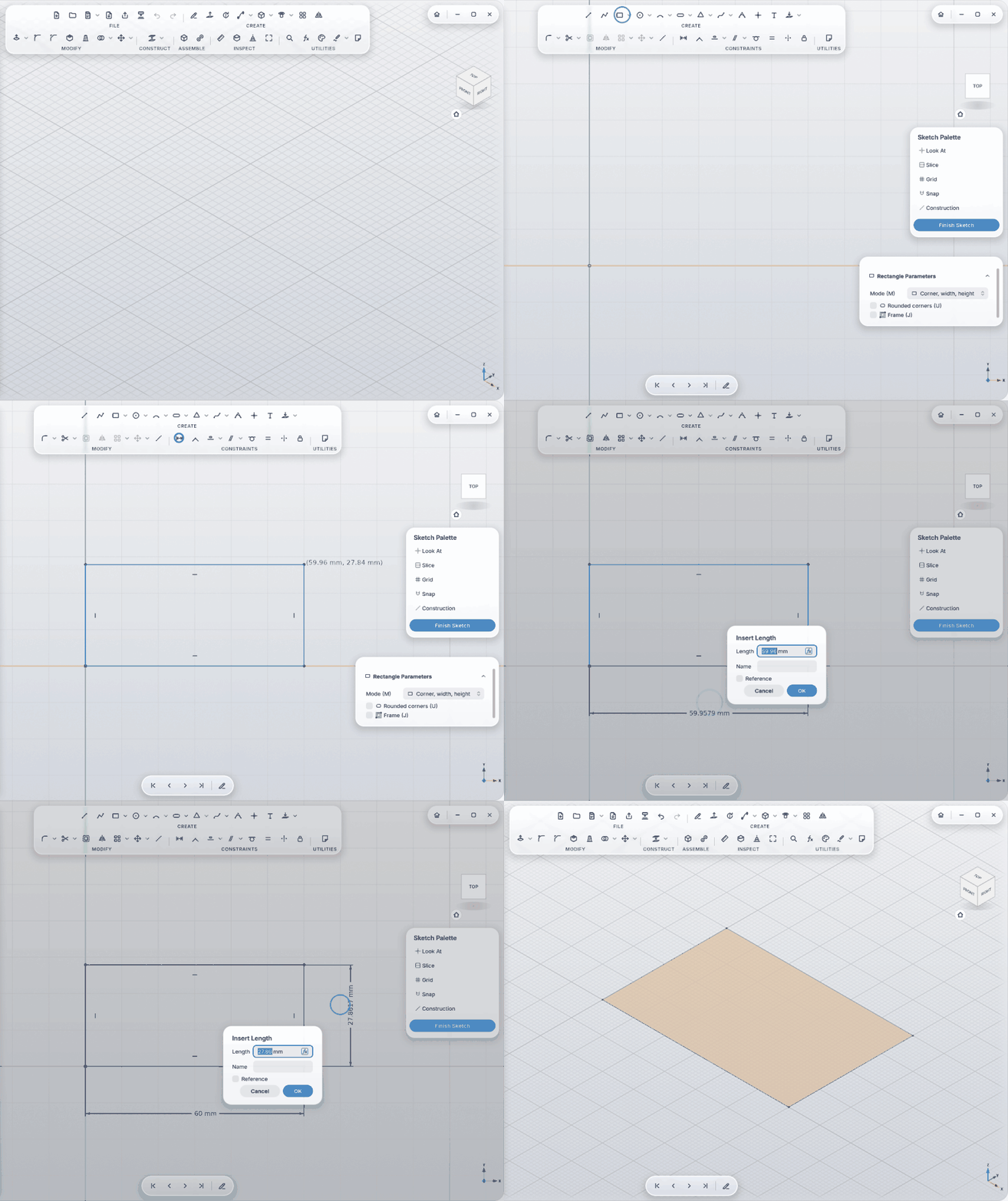
Every closed region is its own profile: two circles inside each other, click the ring, extrude, and you have a tube.
Create: Extrude · Revolve · Sweep · Loft · Rib · Web · Emboss · Box · Cylinder · Sphere · Torus · Coil · Hole · Screw Here · Thread · Pattern · Mirror
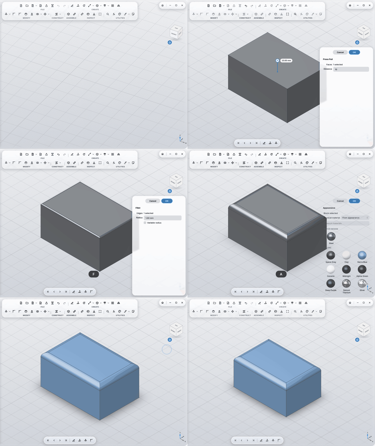
Modify: Press Pull · Fit · Remove Face · Replace Face · Split Face · Fillet · Chamfer · Shell · Draft · Combine · Split Body · Move · Align · Scale
Construct: Offset Plane · Plane at Angle · Midplane · Plane · Axis · Point
Inspect: Measure · Section Analysis · Print View
Worth knowing:
-
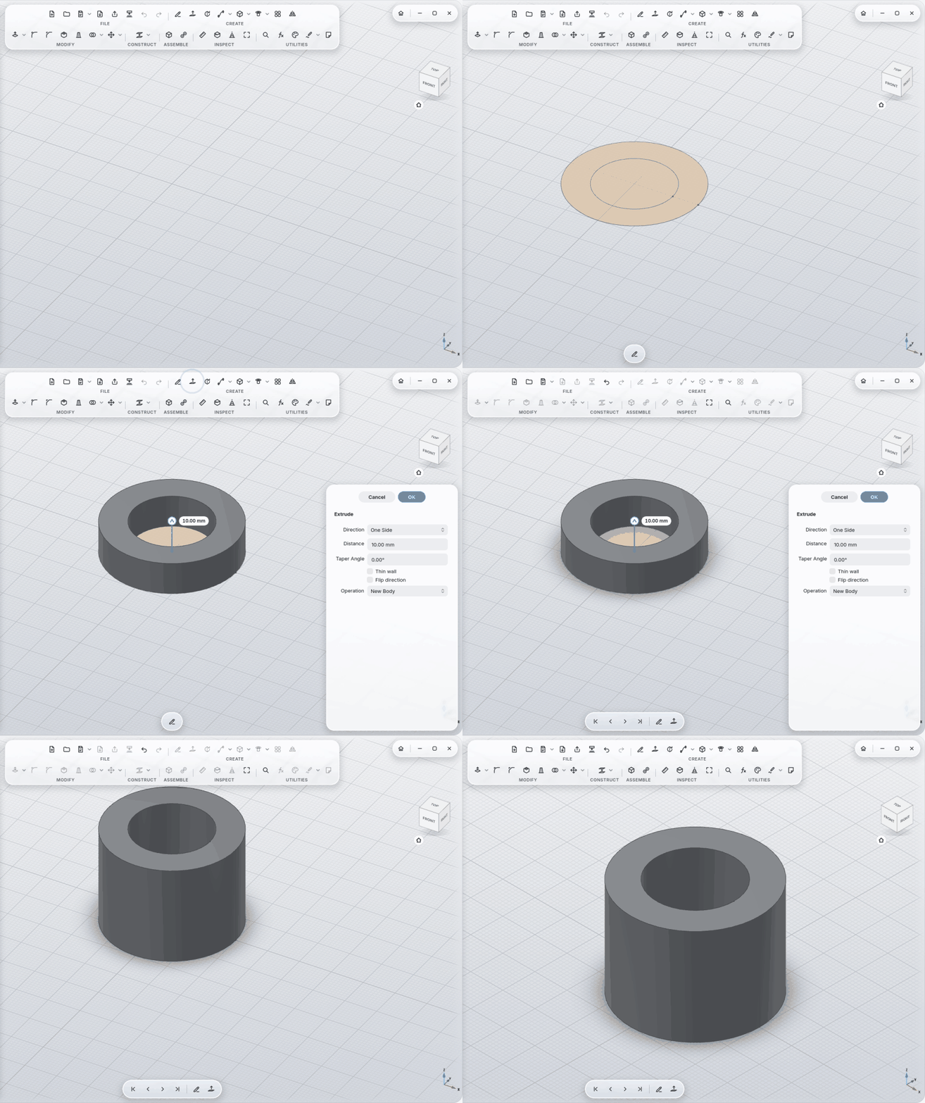
Extrude: one side, symmetric, two sides, up to an object, through all; with a taper angle and as a thin wall. Click a flat face of a body and extrude it, like Press Pull.
-
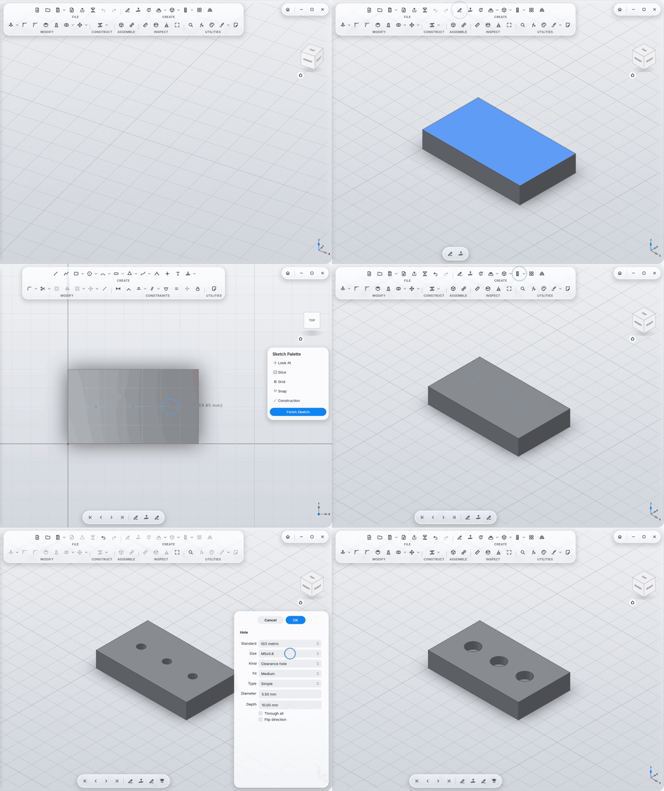
Hole by click: snaps to the middle of the face or the centre of a round face, otherwise to 0.5 mm, and is dimensioned to the two nearest edges.
-
Holes by standard: ISO metric, ISO metric fine, UNC, UNF; clearance hole (fine/medium/coarse) or tapped hole; counterbore or countersink matching the screw (ISO 4762 socket head, ISO 10642 countersunk, ISO 7380 button head); threads can be modeled for real.
-
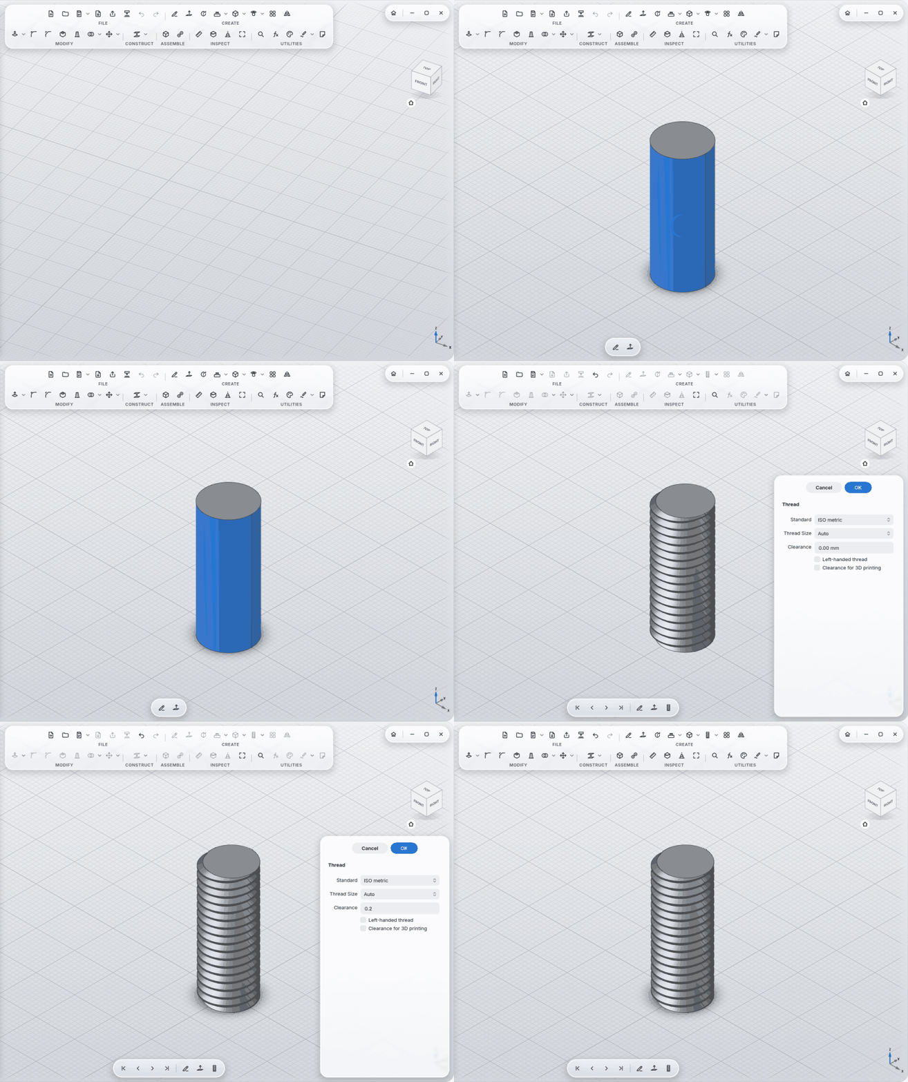
Thread: real, printable ISO thread outside or inside; size picked automatically; clearance for 3D printing; left-handed.
-
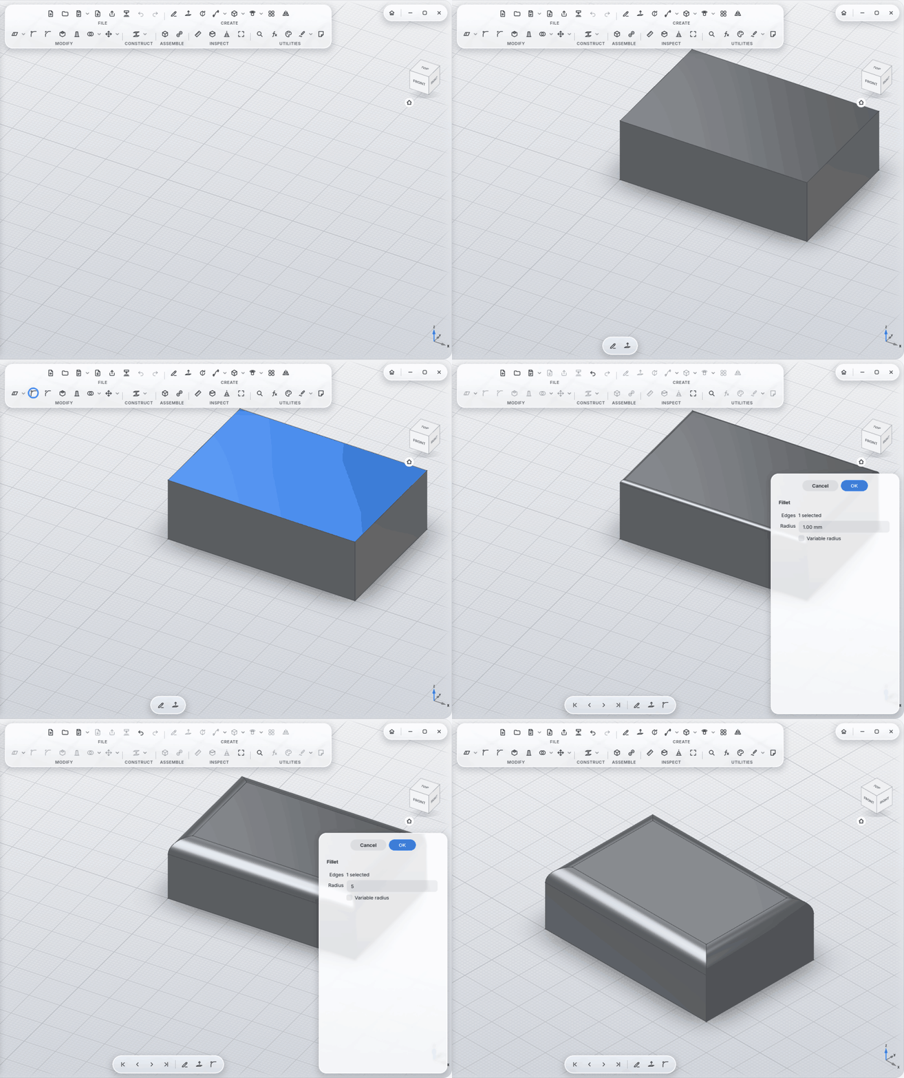
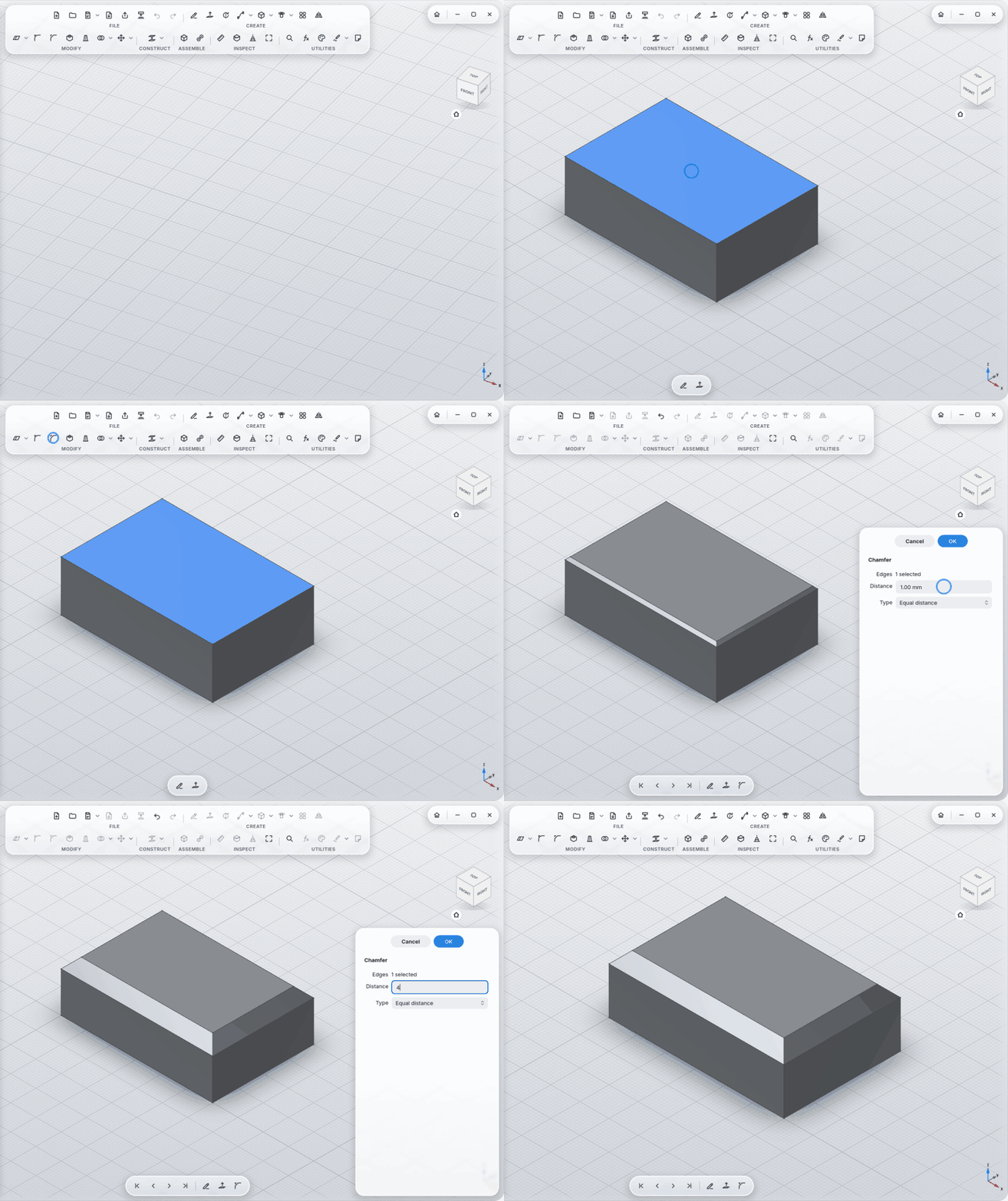
Fillet with a variable radius; Chamfer with equal distance, two distances or distance and angle.
-
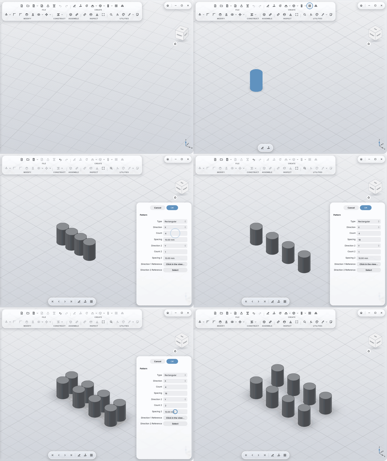
Pattern rectangular, circular or along a path; directions and axes from edges, faces and axes.
-
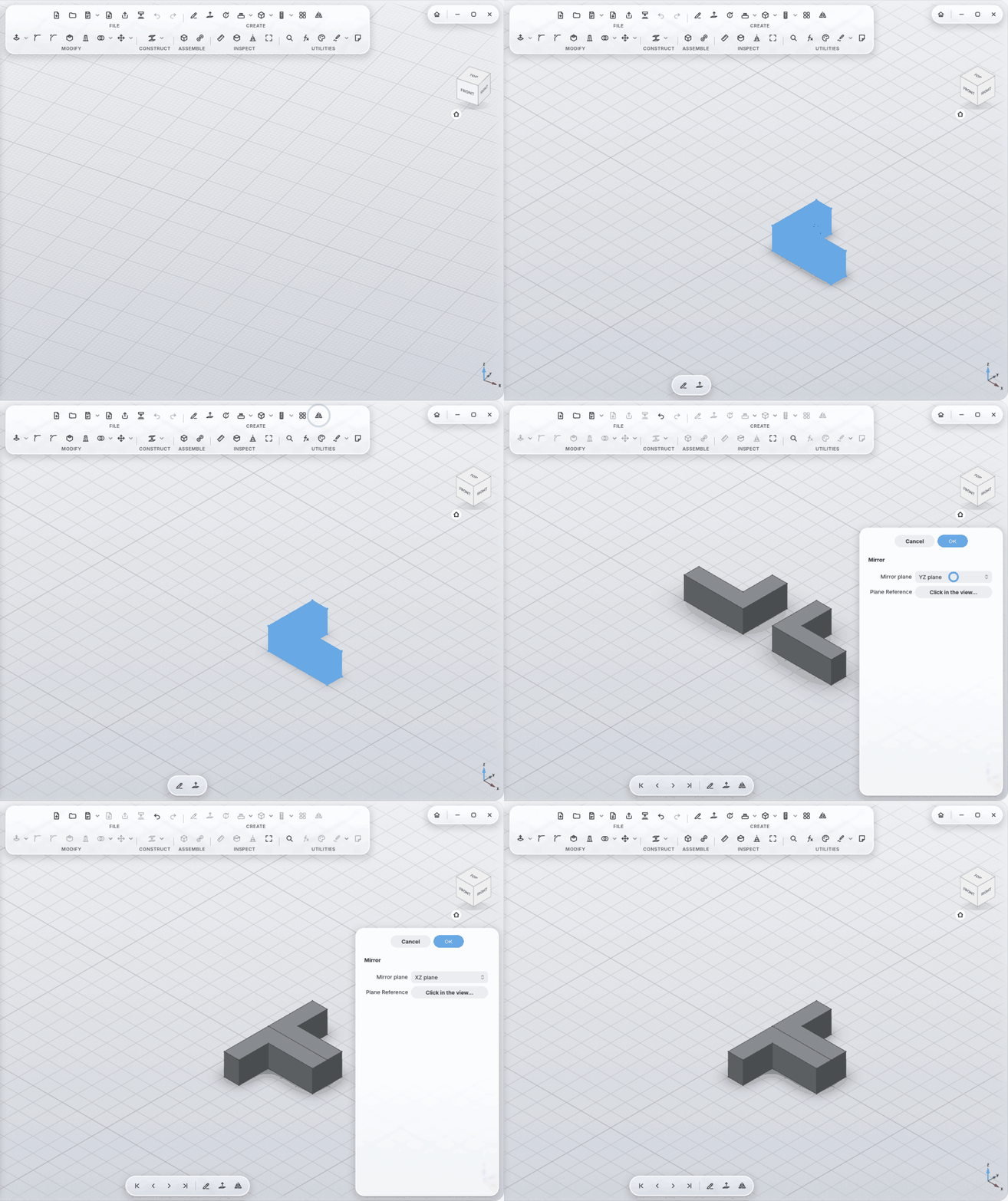
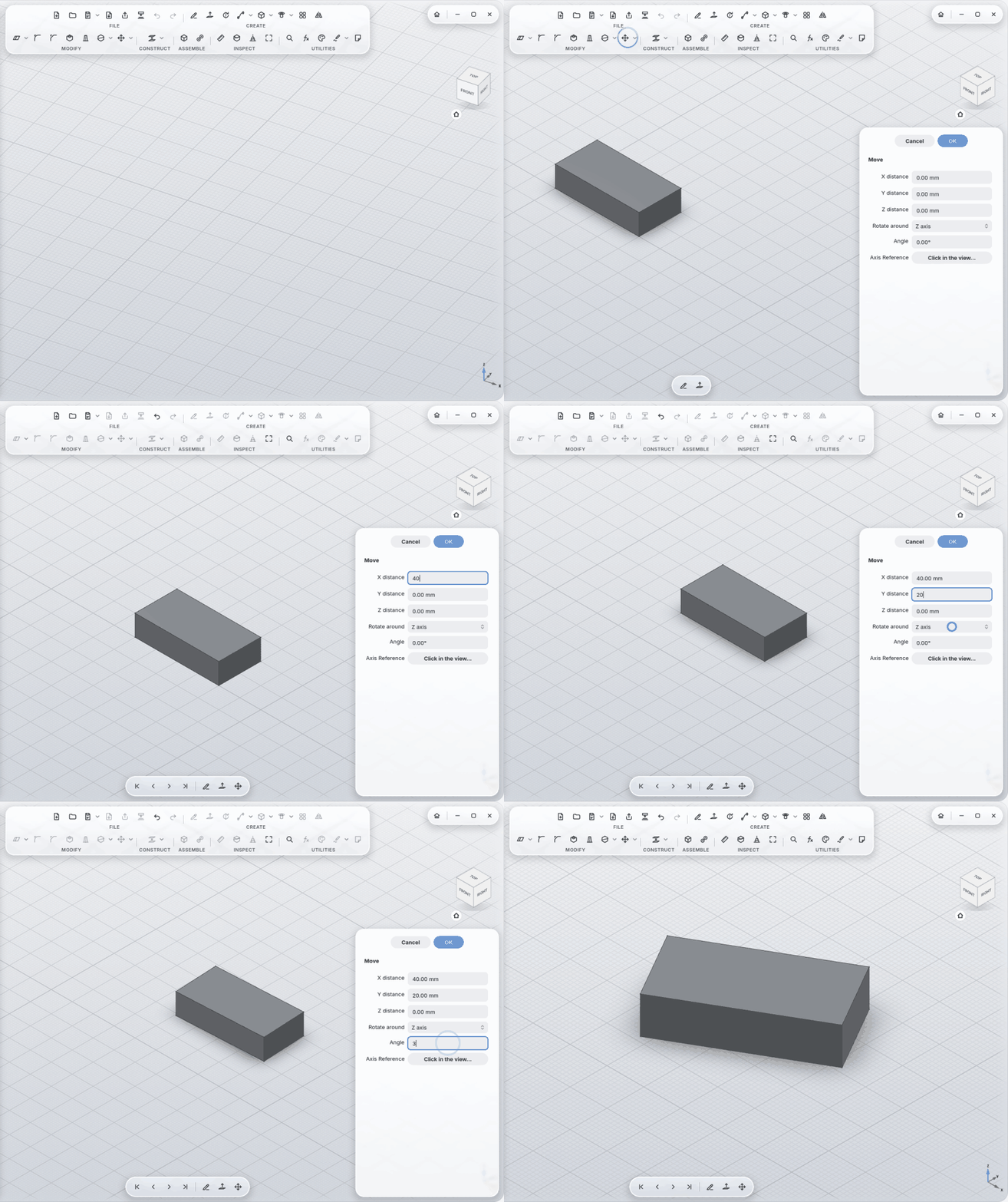
Mirror, Pattern, Move work with any plane, face, edge or axis.
-
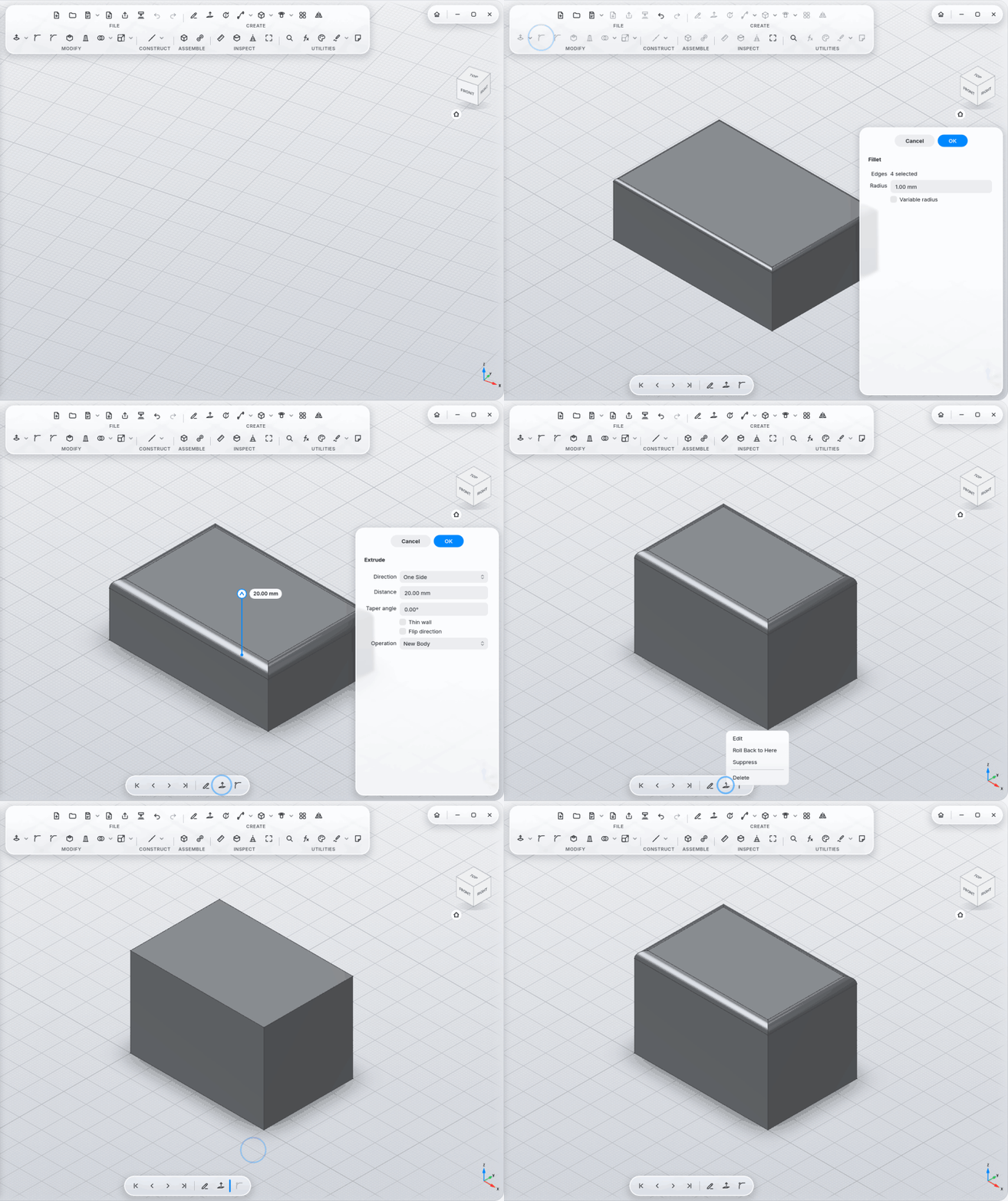
Every step goes into the timeline at the bottom. Roll back, change a step, everything after it follows.
-
Reorder steps by dragging (MyCAD tells you when a step needs another one).
-
Group steps (Ctrl+click, Group Selected Steps); fold groups away, rename them.
-
Errors explain themselves: a red badge on the step, plain words about what's wrong, and a suggestion that works ("radius 2.4 mm still fits"), applied with one click. Edges that may no longer be the ones you picked after a change are marked orange: Show Affected Edges or Looks Right.
-
Numbers the way you write them:
12,5or12.5, units (1 in), calculations (2 * 7,5) and parameter names in every size field, sketch dimensions included.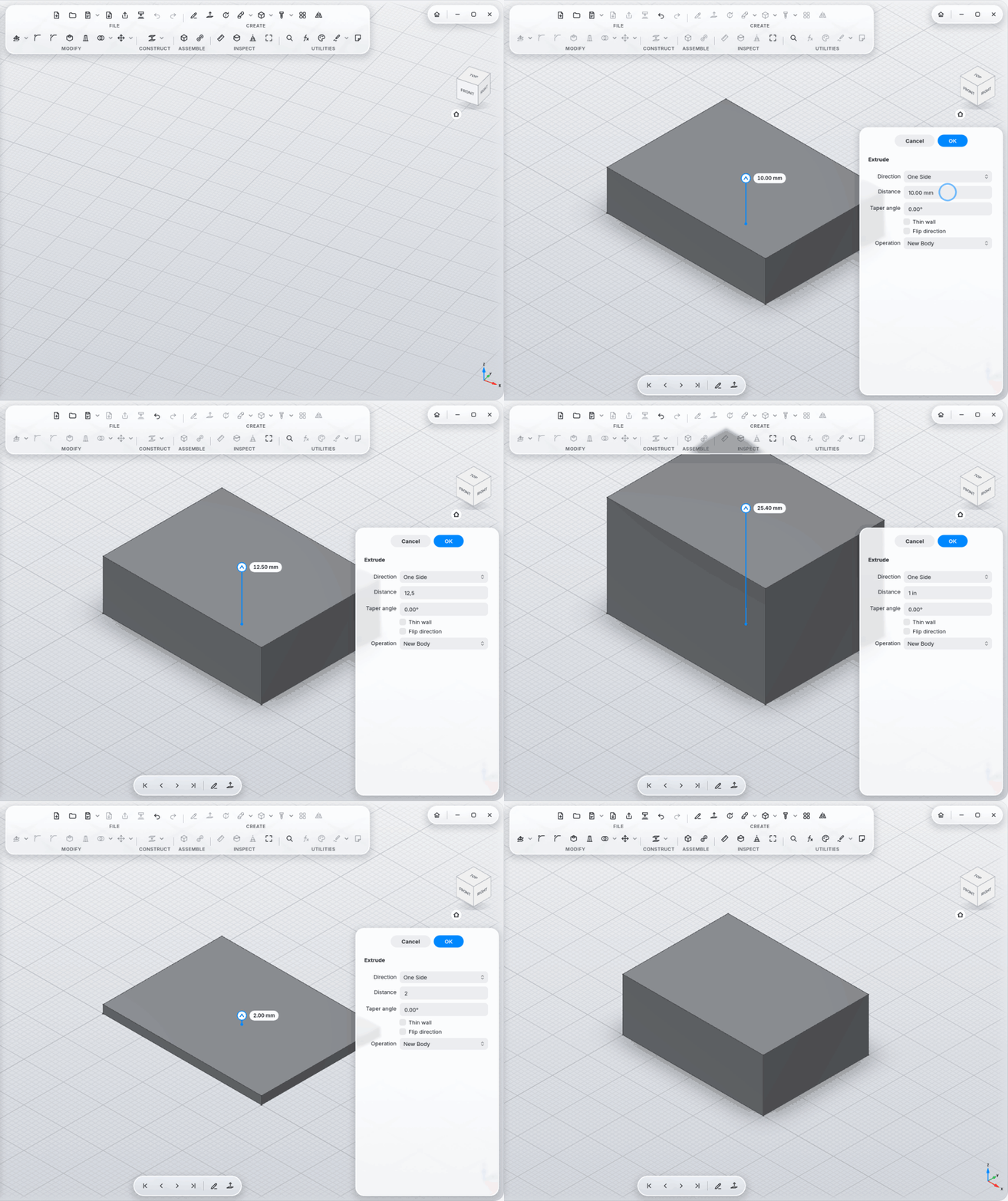
-
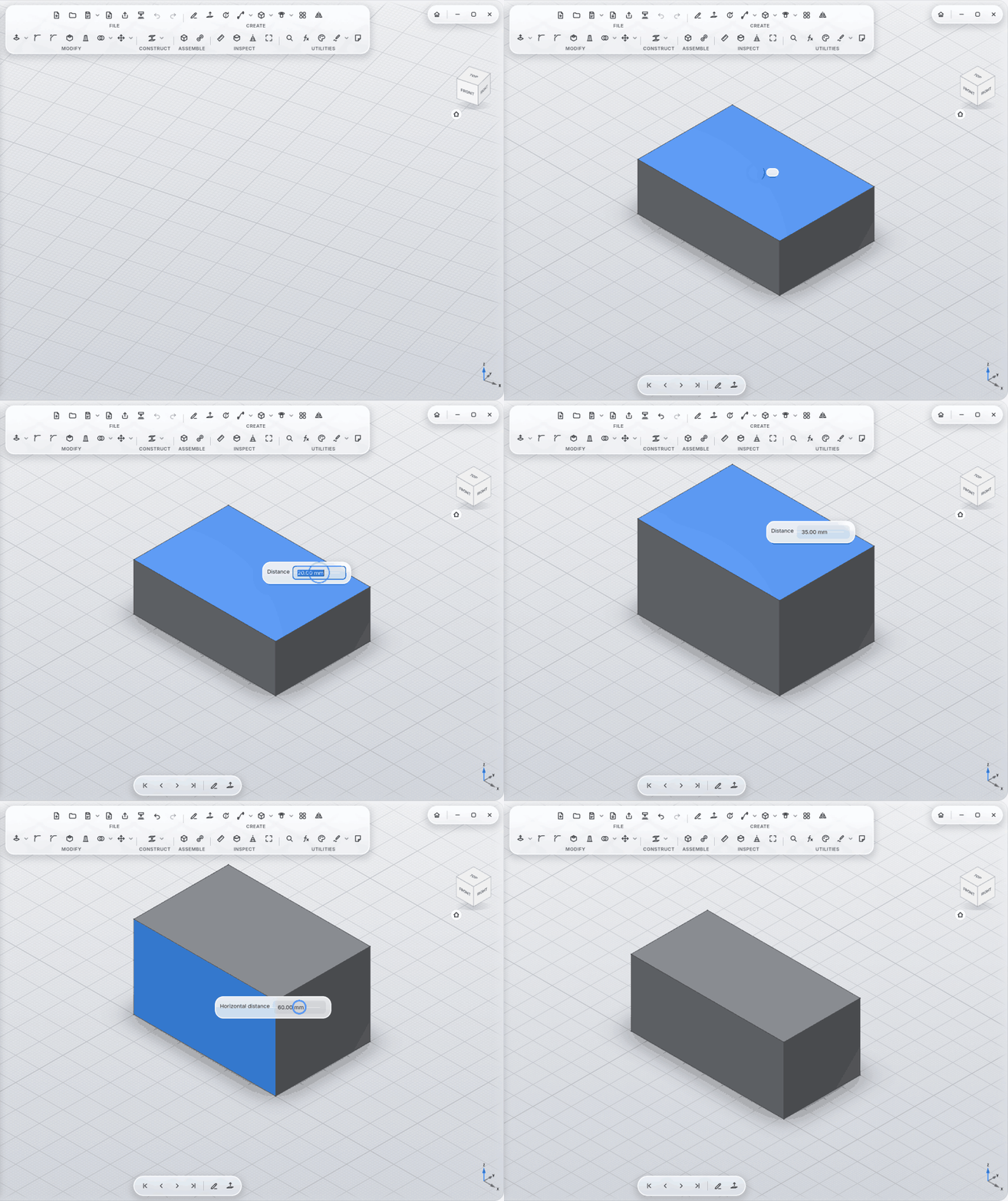
Double-click a face, change a number: double-click a face with no tool active and the sizes that make it appear on the model: extrusion length, the sketch dimension behind a side face, hole diameter, fillet radius. Type, Enter, done. Ctrl+Z works.
-
Change Parameters: named values and formulas (
Width = 40 mm,Height = Width / 4) for every size field.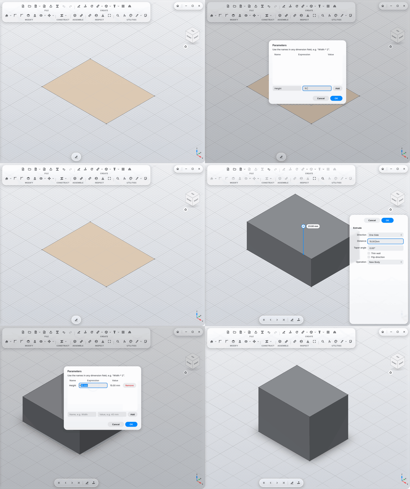
-
A note is your parameter list:
Wall = 2 mmin a note creates the parameter; formulas show their value (Width = Wall * 20 → 40.00 mm); change the size on the model and the note changes too. -
Configurations in the note:
Size: S | M | L, values one per size (Width = 40 mm | 60 mm | 80 mm); the sizes are buttons on the note and switch the part with one click. -
Notes calculate:
120 / 4 =gives30, with units (10 mm + 1 in = 35.40 mm) and parameter names.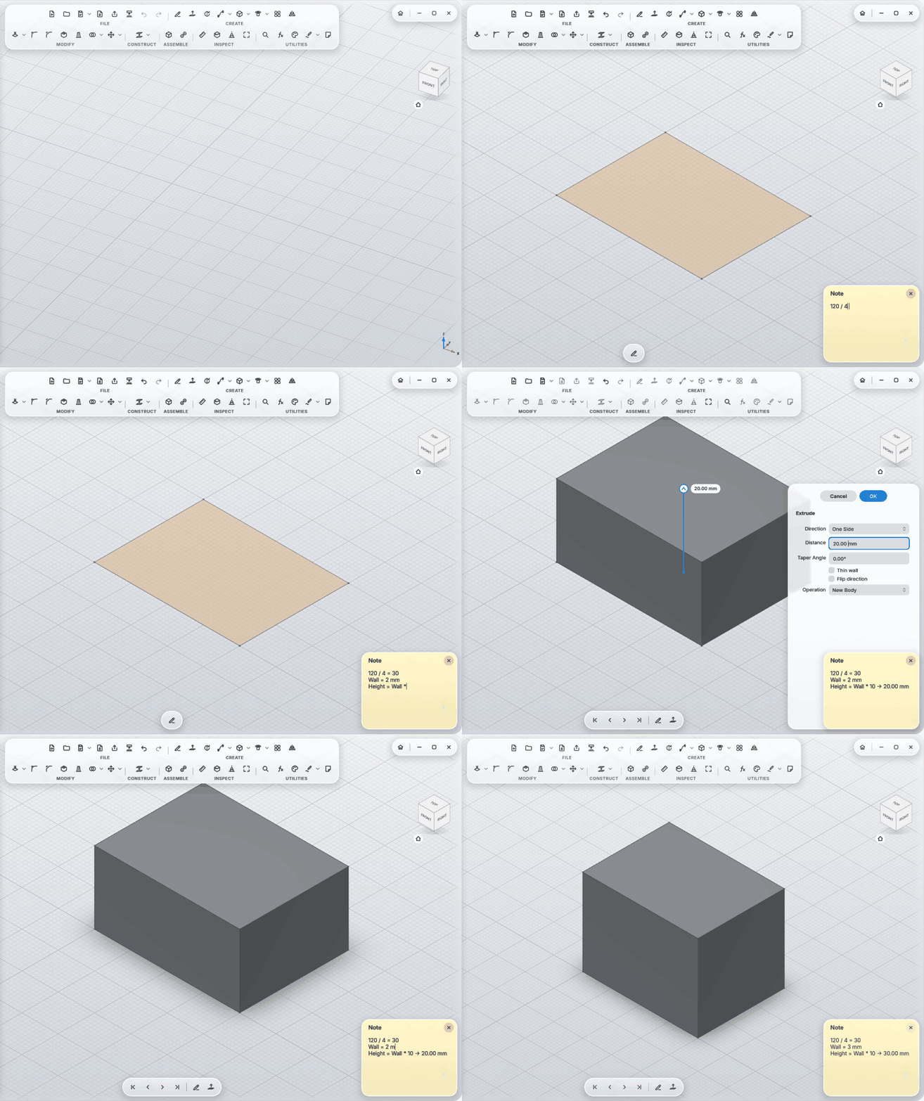
-
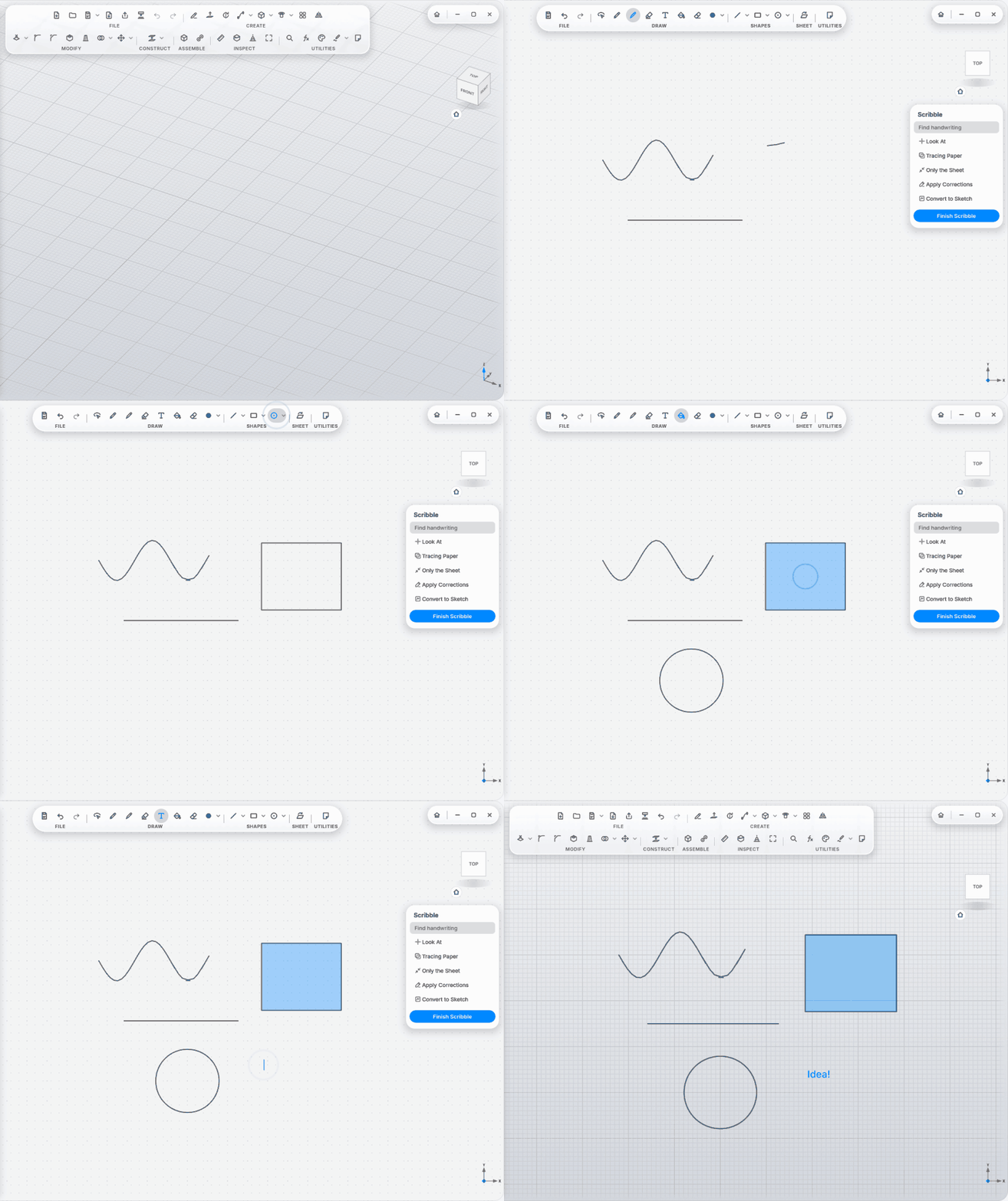
Scribble: a drawing sheet with pen pressure; pencil, fineliner, marker, eraser; shapes (line, arrow, rectangle, triangle, hexagon, circle, ellipse), fill, text, select and move.
-
Straight lines, circles and rectangles when you hold still; handwriting tidies itself up.
-
Reads handwriting offline: find text on a sheet, CAD notation (o12 → Ø12, 2x45 → 2×45°).
-
Move Sheet onto any face or upright along a stroke: sketch in 3D.
-
Convert to Sketch: strokes become a real sketch; a written
Ø12next to a circle becomes its dimension. -
Red Pen: write corrections right on the model, such as
R2,C2,2×45°,+5,−5,M5,Ø8,H7,print,3×, a size,remove, or a line through a face. Each one becomes a card with Show, Apply and Discard.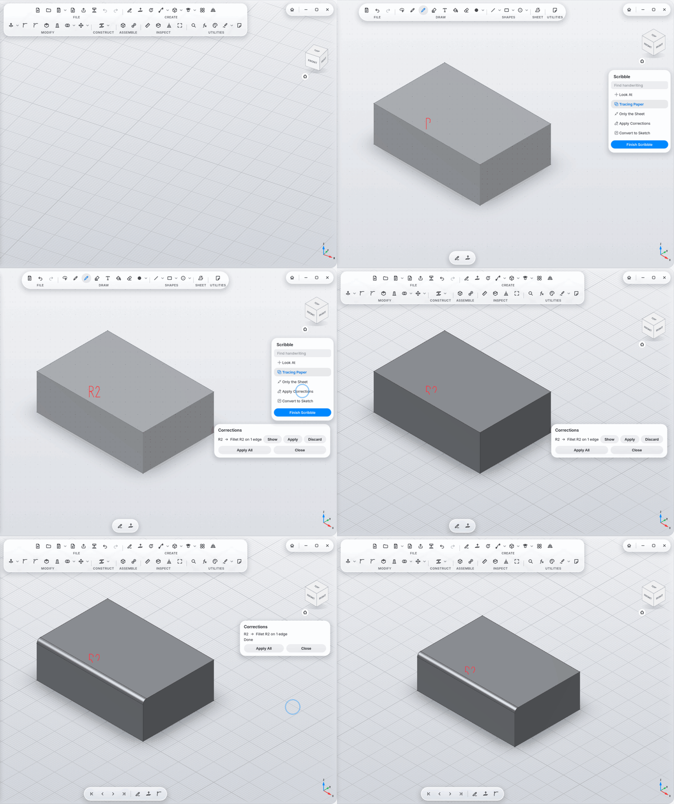
-
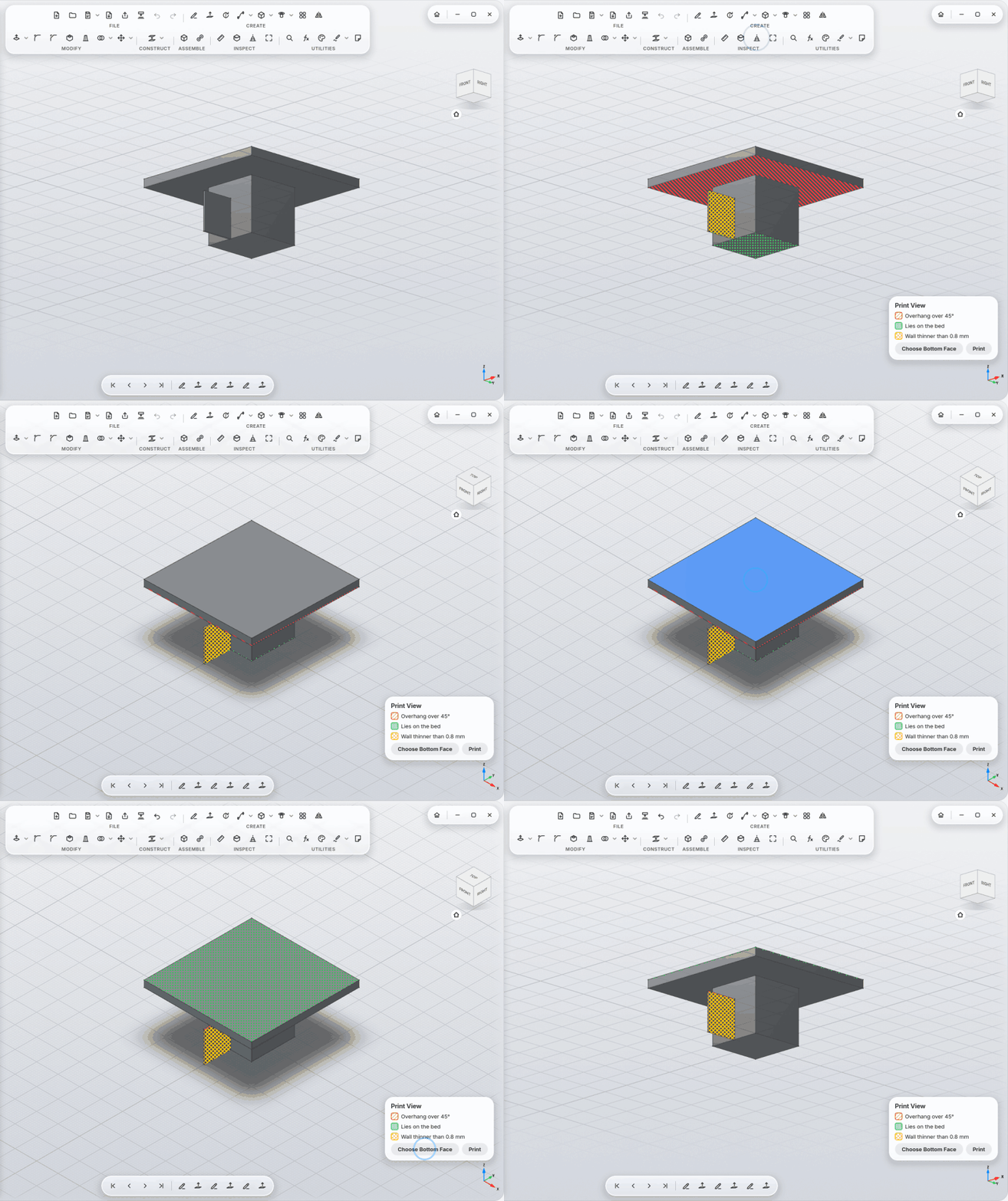
Print View: overhangs (hatched red), faces on the bed (dotted green), walls that are too thin (cross-hatched yellow); Choose Bottom Face sets the print direction. Overhang angle and minimum wall in Settings.
-
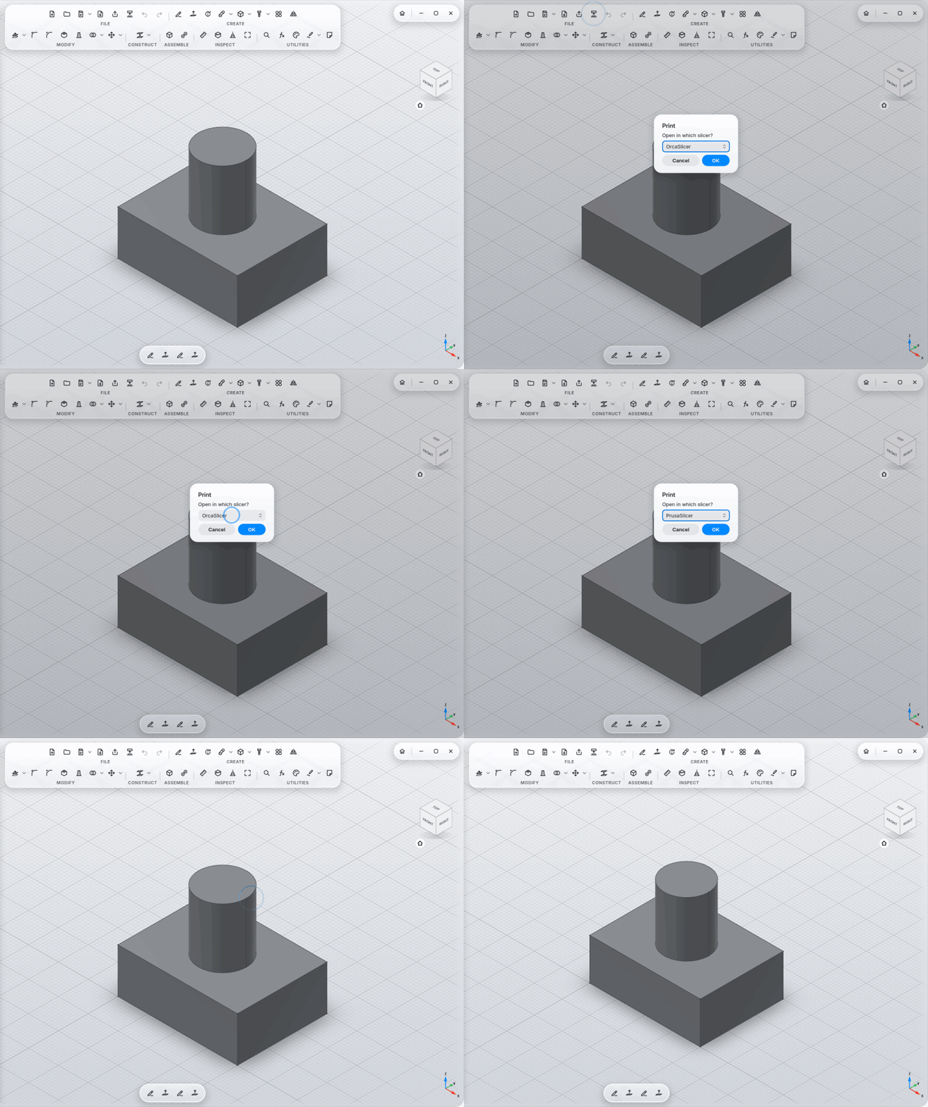
Print: opens the design as a colored 3MF in your slicer: OrcaSlicer, Bambu Studio, PrusaSlicer, UltiMaker Cura, installed as a program, Flatpak or AppImage. Remembers your choice.
-
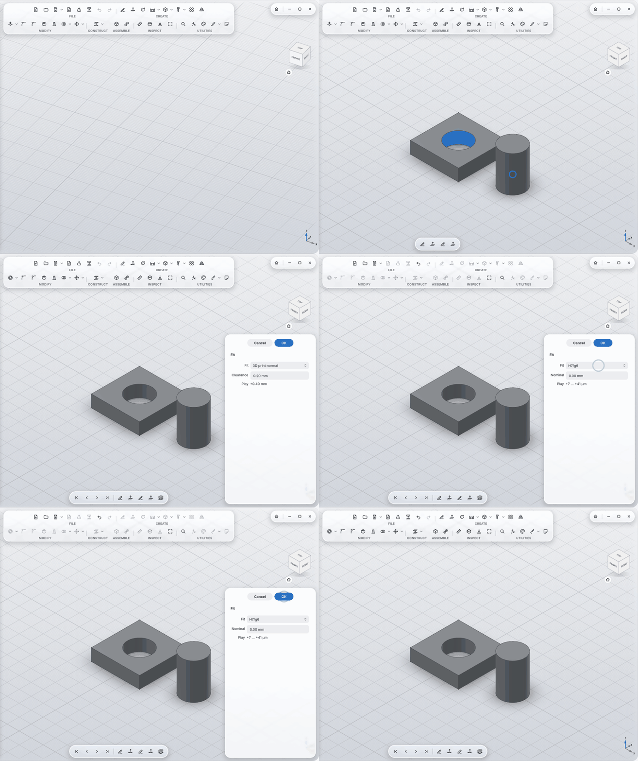
Fit: a hole and its pin to ISO 286 (H7/g6, H7/h6, H7/k6, H7/p6, H8/f7) or with print play (tight/normal/loose, adjustable). The play shows in the panel.
-
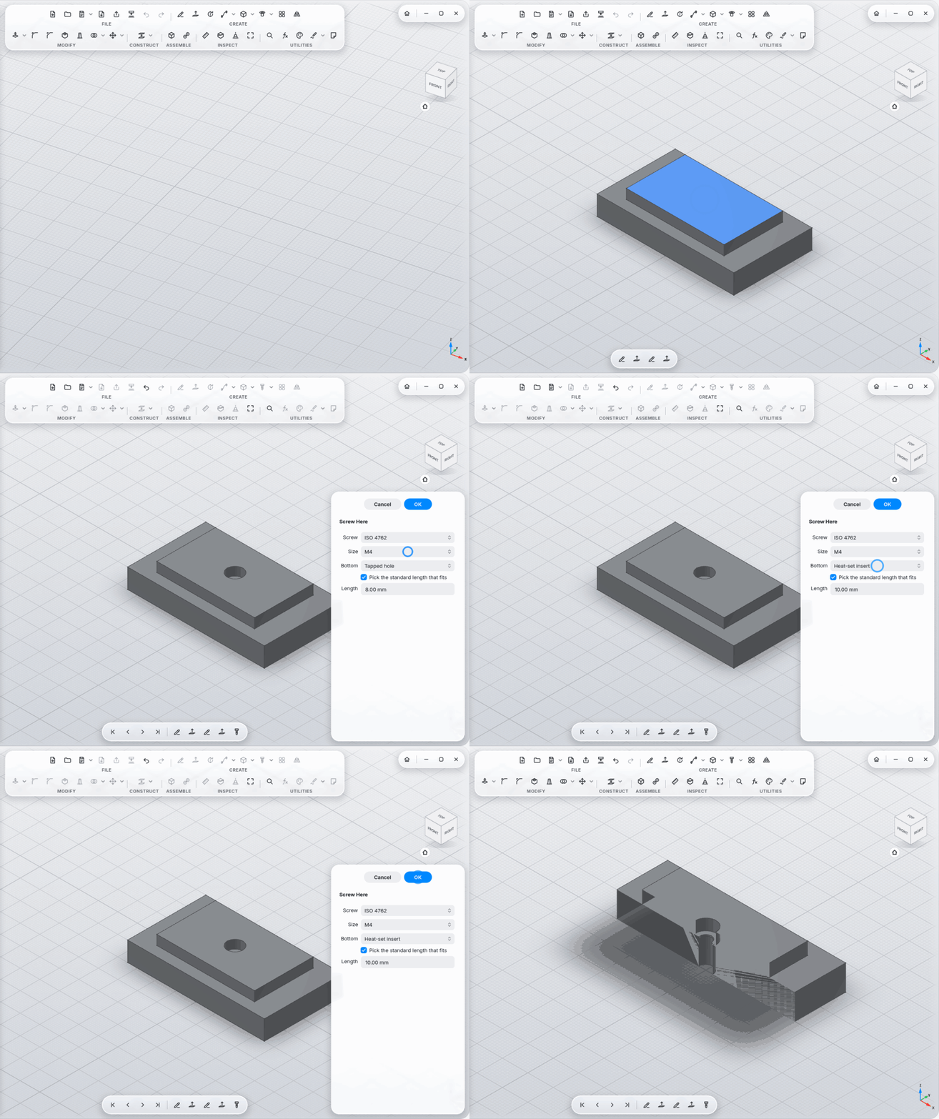
Screw Here: one click joins two parts: clearance hole with counterbore at the top, tapped hole, heat-set insert or nut trap at the bottom; the screw length is picked from the standard.
-
Threads for printing: the play is added automatically, with a warning when the pitch is too fine.
-
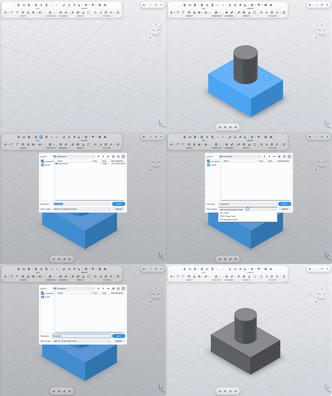
Export as 3MF (colors, names), STL, STEP (with colors), DXF (sketches); resolution coarse/normal/fine.
-
Always saved: after every step, as soon as MyCAD rests for 2 seconds. New designs get their own folder in the projects folder. Closing never asks. If something crashes, at most 2 seconds are missing.
-
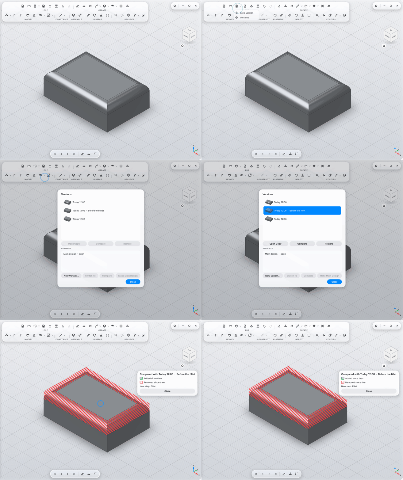
Save Version (Ctrl+S) gives the current state a name.
-
Versions: every state is kept, the way Time Machine keeps backups. View with preview, compare (a ghost over the model: added in green, removed in red, plus the changed steps) and restore (never deletes anything).
-
Variants: try a "what if" as a copy, switch in the browser, compare, make it the main design.
-
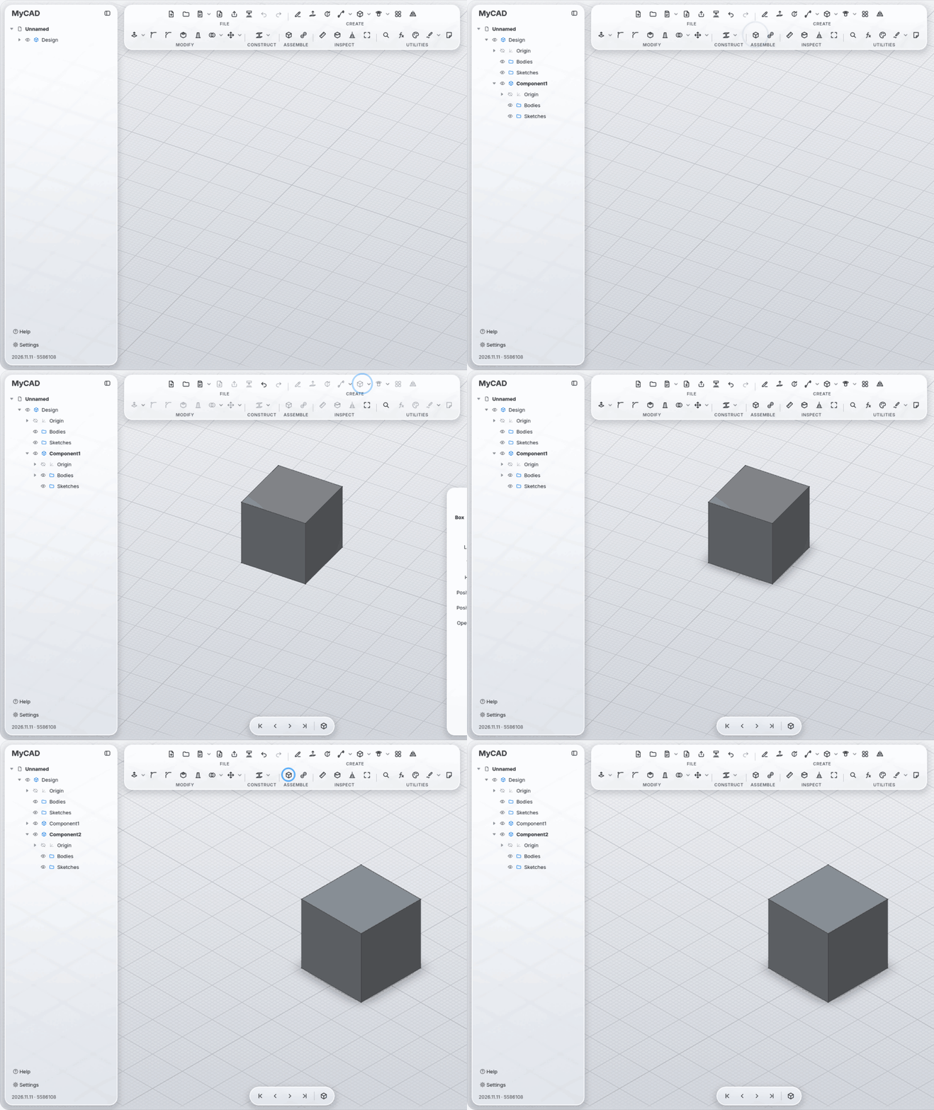
Components with their own bodies, sketches and origin, all in one file.
-
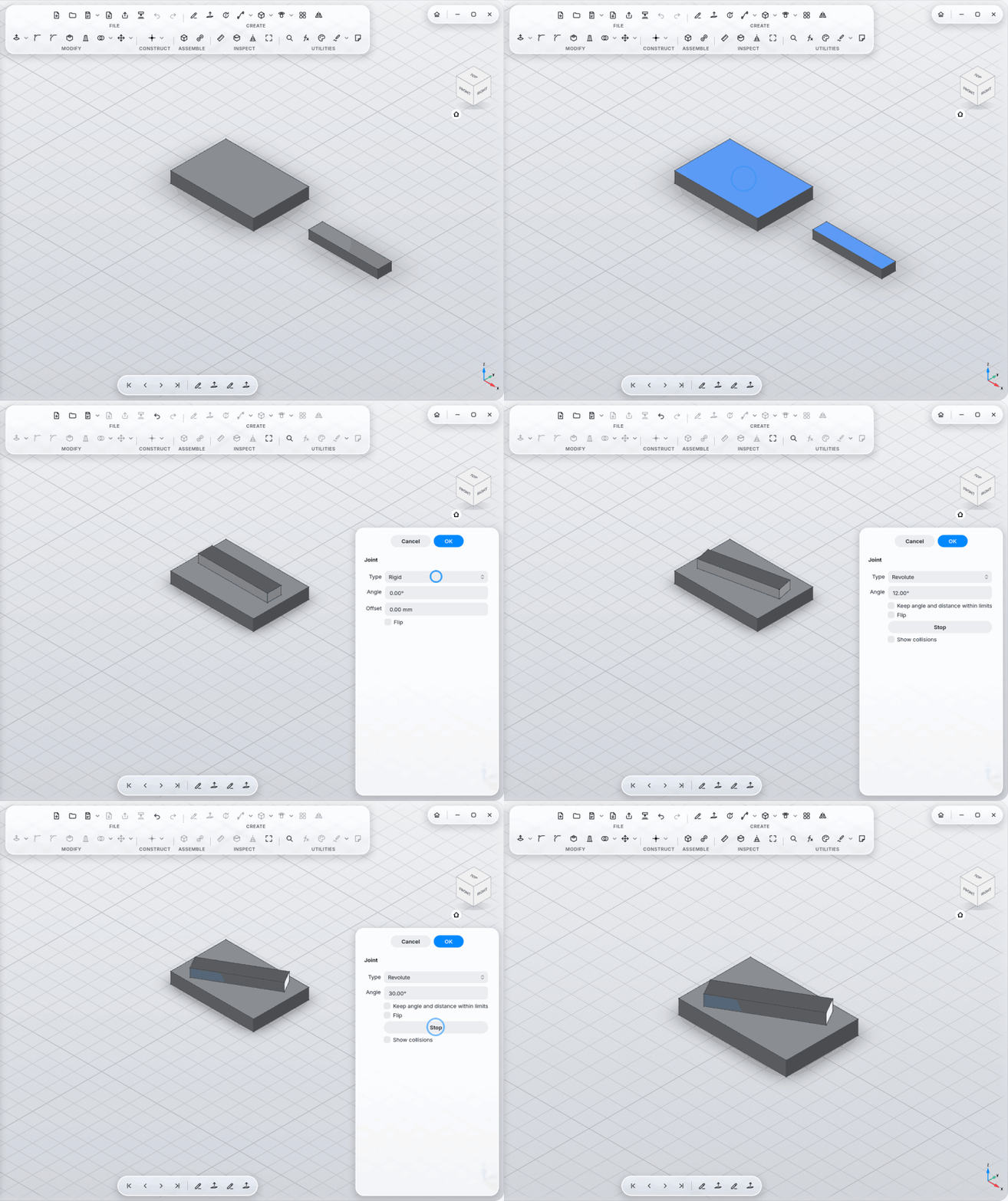
Joints: Rigid, Revolute, Slider, Cylindrical, Pin-Slot, Planar, Ball; angle and travel with limits.
-
Chains: a part joined to a moving part moves along.
-
Closed loops (a four-bar linkage, say) solved together; the first joint drives, the others follow.
-
Animate with collision reporting.
-
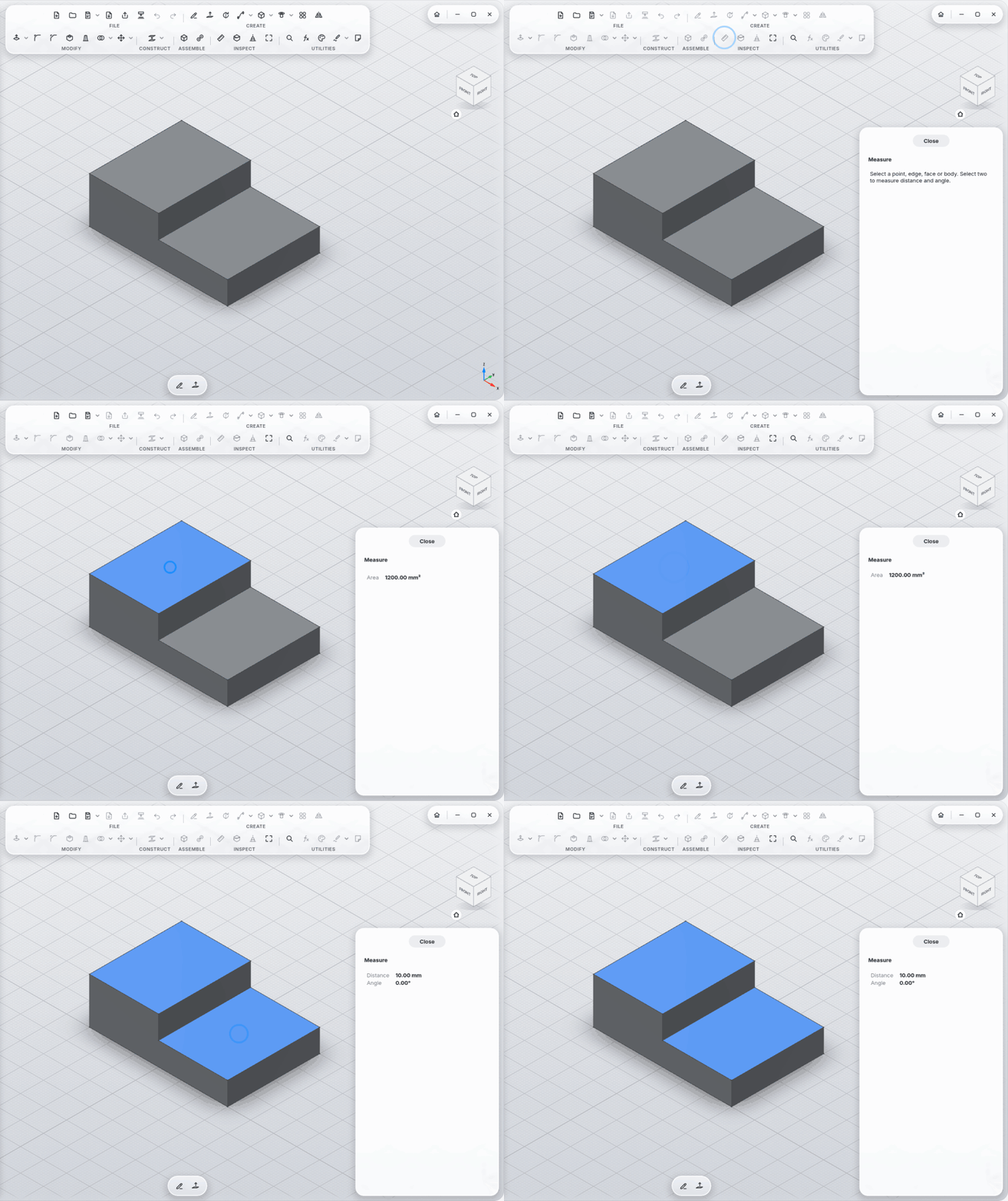
Measure: distances, angles, areas, volumes; for a whole body also mass, material and center of mass.
-
Measure without the tool: select two faces, edges or points and a small card shows their distance, or their angle if they touch; a cylinder or circle alone shows its diameter. Click the value to turn it into a parameter.
-
Appearance sets the matching physical material (density) too; your own choice stays.
-
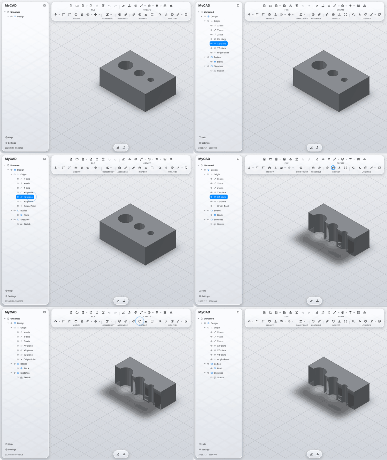
Section Analysis, Print View.
-
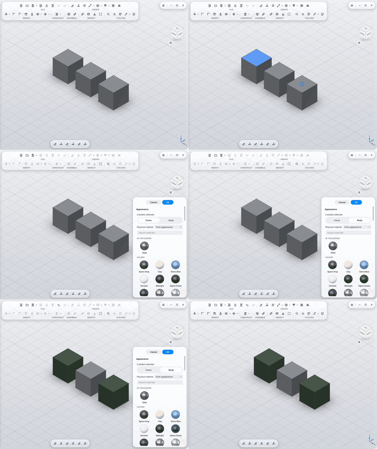
119 materials (metals, anodized, coatings, plastics, PLA with print layers, rubber, glass, wood, stone, leather, carbon …), many as real photo scans with relief and end grain.
-
Studio lighting (every face its own shade) or a soft room; reflections, clear coat, contact shadow, each one can be turned off.
-
Drag a material sphere onto a body; color single faces.
-
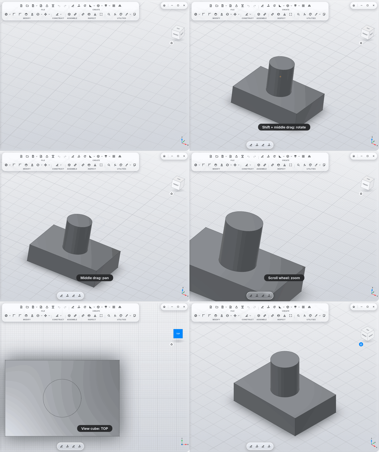
12 navigation styles (Fusion 360, SolidWorks, Blender, Touchpad and more); keys as mouse buttons.
-
Pen tablets with pressure and hover on Wayland; the side buttons navigate.
-
Shortcuts: see Controls and Settings.
-
Own format
.mycad(a ZIP with a preview image, the same content as FreeCAD's.FCStd);.FCStdopens too. -
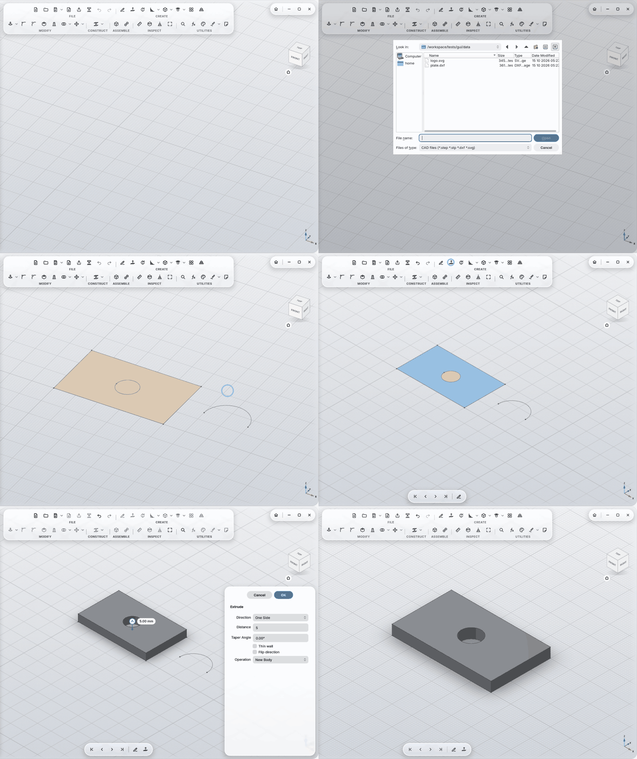
Import: STEP (one body per solid), DXF and SVG into a sketch.