Repository navigation
Tutorial Assembly
You build a lever that turns on a base plate, screw two parts together in one click, and close a chain into a four-bar linkage.
The built-in help has a short version of this tutorial: ? → Getting Started → Tutorial: an assembly with joints.
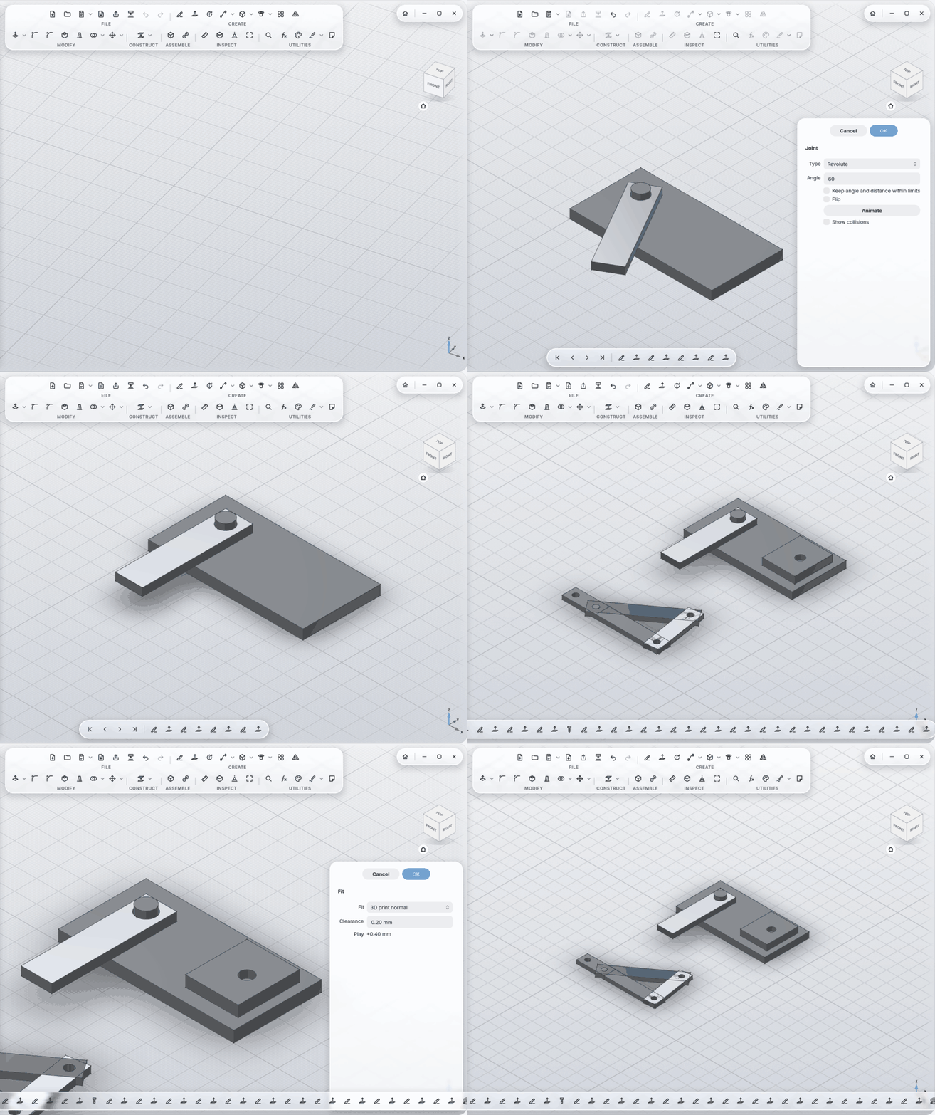
- New design, a plate 80 × 40 × 5 mm (sketch, extrude). It belongs to the design itself and never moves.
- New Component (ASSEMBLE section). It shows up in the browser; everything you build now belongs to it.
- Inside the component, build a strap 60 × 10 × 3 mm with a Ø6 hole at one end.
- Joint (key J).
- First click something on the component that should move: the hole face of the strap.
- Then the place it should go to: a hole in the base plate, or its top face.
- In the panel, pick the Type: Revolute. Angle turns the lever.
Types: Rigid (fixed), Revolute (around the axis), Slider (along the axis), Cylindrical (both), Pin-Slot (turn and slide in a slot), Planar (in a plane), Ball (in every direction).
- Tick Keep angle and distance within limits and enter, say, −45° … 45°.
- Animate swings the joint back and forth between its limits.
- Show collisions reports when parts touch: "Collision: Lever touches Base".
Build a second component and join it to the lever instead of the base plate. When the lever turns, it moves along.
A four-bar linkage has a fixed frame, a crank, a coupler and a rocker. The rocker hangs on the end of the coupler and on the frame, so the chain is closed.
- Crank to the frame with Revolute, coupler to the crank with Revolute, rocker to the coupler with Revolute.
- Use the joints' angles to turn the parts roughly the way the linkage should sit. That decides which way the chain folds later.
- Give the rocker a second joint back to the frame.
Now a solver works out the whole chain together. The first joint of the chain (the crank here) drives it with its angle, and the others follow. If a following joint would have to leave its limits, it says so. If the joints contradict each other (two joints want the part in different places), the joint shows an error instead of quietly settling for a compromise.
- Lay a second plate on the first.
- Click the top face of the upper plate where the screw should go (or the edge of a round hole, to hit its center exactly).
- Screw Here (CREATE section, arrow ▾ next to Hole).
- Choose the screw (ISO 4762 socket head, ISO 10642 countersunk, ISO 7380 button head), the size (M2 to M12) and what holds it at the bottom: Tapped hole, Heat-set insert or Nut trap. The matching standard length is already filled in.
At the top you get a clearance hole with counterbore or countersink; at the bottom a core hole, a hole for the brass insert or the hexagon pocket.
Ctrl+click the hole and the pin, Fit (MODIFY section). For the printer, "3D print normal" makes the hole 0.2 mm wider on each side. For the workshop, H7/g6 for example puts both faces in the middle of their tolerance field, and the panel shows the play ("+7 … +41 µm").
Click a body, Measure: volume, mass, material and center of mass. The material follows the appearance (brushed aluminum → aluminum); you can also choose it yourself under Appearance.
Next: Assemblies · 3D Printing · Features