Repository navigation
Assemblies
A step-by-step example is in the Tutorial: an assembly with joints.
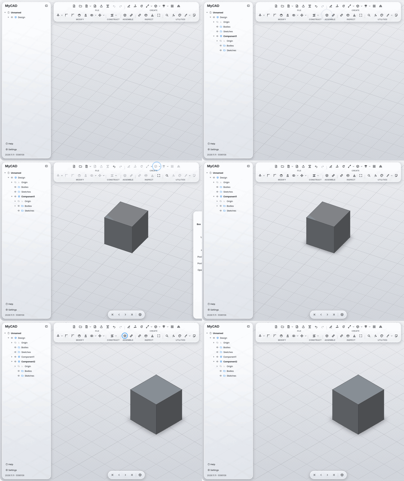
New Component (ASSEMBLE section) creates a component with its own origin, bodies and sketches. What you build goes into the active component. Everything stays in one file. The design itself (the root) never moves.
Joint (key J): first an element on the component that moves (face, edge, hole, point), then the place it should go to. Two flat faces lie on each other; Flip turns that around.
| Type | Motion | Values |
|---|---|---|
| Rigid | none | angle and offset as a fixed position |
| Revolute | around the axis | Angle |
| Slider | along the axis | Offset |
| Cylindrical | turn and slide | Angle, Offset |
| Pin-Slot | turn and slide in the slot | Angle, Offset |
| Planar | slide and turn in the plane | Offset, Offset 2, Angle |
| Ball | turn in every direction | three angles (yaw, pitch, roll) |
-
Keep angle and distance within limits: minimum and maximum for angle and travel.
-
Animate: the joint swings between its limits.
-
Show collisions: reports which parts touch while it moves.
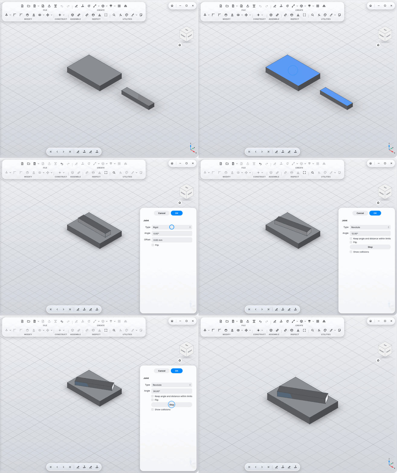
A part joined to a moving part moves along.
When a component gets a second joint (the last link of a four-bar linkage back to the frame, say), the chain is closed. Then a solver (OndselSolver, as in FreeCAD's Assembly workbench) works out all joints of the chain together:
- The first joint of the chain drives with its angle or travel, rigid joints stay rigid, and the others follow.
- Before closing the chain, turn the parts roughly the way it should sit. That picks the way it folds. A fully stretched chain is folded by MyCAD itself.
- Limits of the following joints are checked: if the mechanism would have to go past them, the joint says so.
- If joints contradict each other (two fixed positions for the same part), the joint shows an error.
- Every joint type works in closed loops, Pin-Slot included.
Measure shows volume, mass, material and center of mass for a whole body. The material comes from the Appearance (wood → wood, brushed aluminum → aluminum); choose it yourself under Appearance → Physical material and it stays.
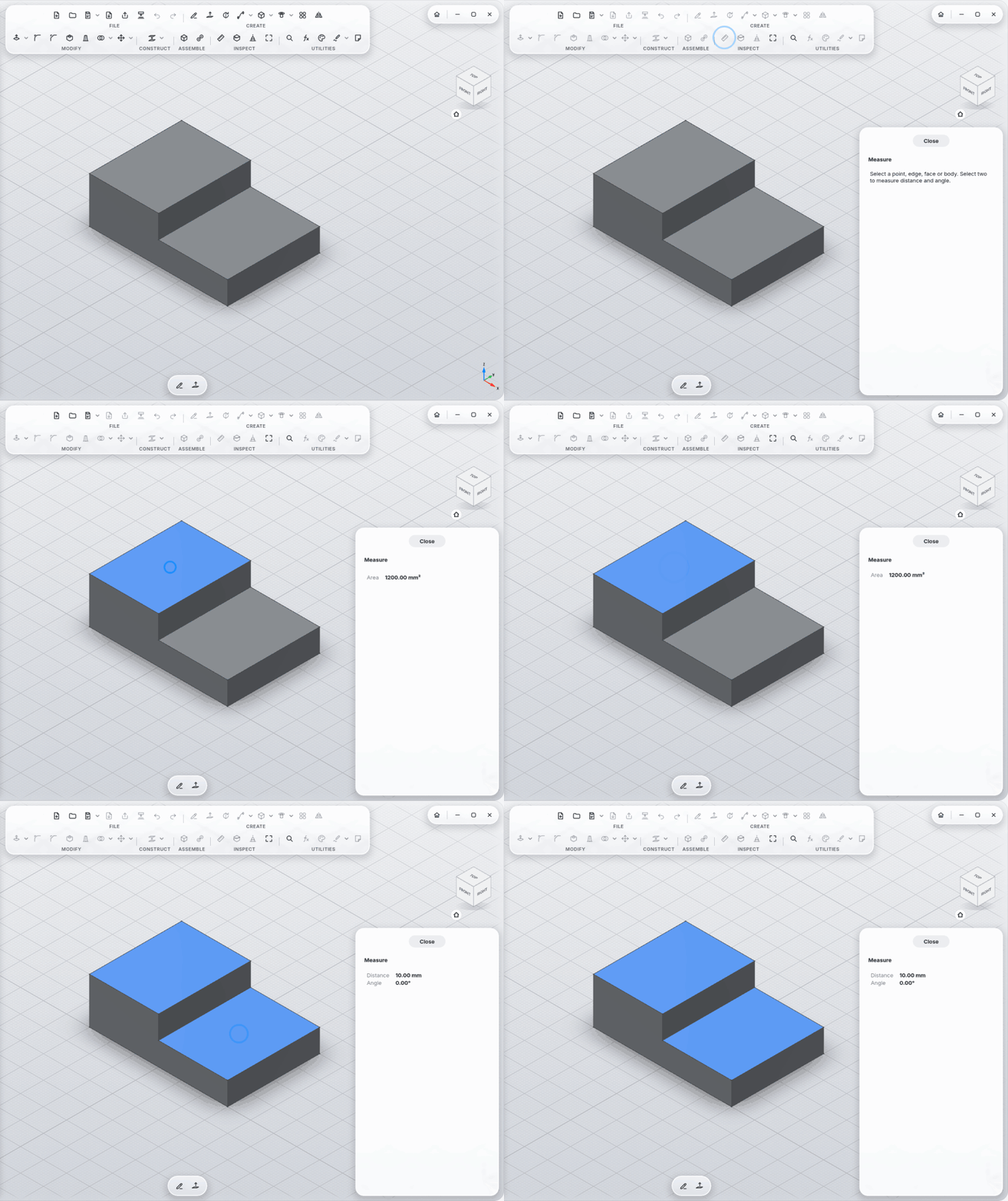
You often don't need the tool at all: select two faces, edges or points (Ctrl+click) and their distance shows in a small card right below them, or their angle if they touch; a cylinder or circle alone shows its diameter. Click the value and the Parameters window opens with it filled in: type a name, Enter.