Repository navigation
3D Printing
MyCAD is made for people who print. Everything that matters is built in, from the play between parts to your slicer.
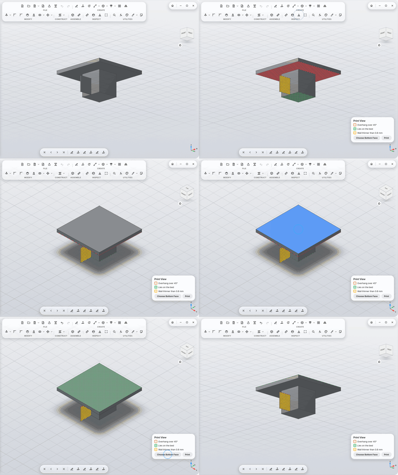
Print View (INSPECT section) shows on the model what your printer will struggle with. Patterns, not just colors, so it reads without color vision too:
| Pattern | Meaning |
|---|---|
| hatched red | overhang flatter than the overhang angle (45° by default): needs supports |
| dotted green | lies on the print bed |
| cross-hatched yellow | wall thinner than the minimum wall (0.8 mm by default) |
-
Choose Bottom Face: click the face that should lie on the bed, then Choose Bottom Face in the legend. The print direction is saved with the design and used by Print.
-
Make printable: the legend lists what one setting would fix, with Apply (or Apply All; Ctrl+Z undoes):
- a hole across the print direction becomes a teardrop with a 45° tip (no supports inside the hole),
- a fillet chamfers its bottom edges at 45° and stays round on top,
- a shell or thin-wall extrude that is too thin grows to the minimum wall. The same options are in the Hole and Fillet panels (Teardrop for printing, Chamfer bottom edges for printing).
-
Overhang angle and minimum wall are in Settings.
-
The Print View button stays pressed while it is on; Exit Print View in the legend (or another click on the button) hides it.
Print (FILE section, or in the legend) opens the visible (or selected) bodies in your slicer: as a 3MF with names and colors, the chosen bottom face down.
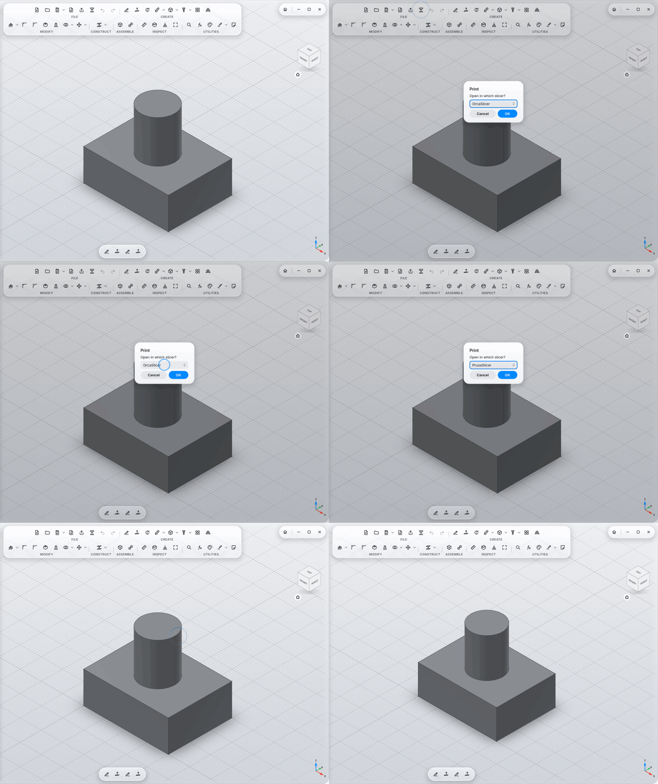
MyCAD finds:
| Slicer | as a program | Flatpak | AppImage in ~/Applications
|
|---|---|---|---|
| OrcaSlicer | orca-slicer |
io.github.softfever.OrcaSlicer |
OrcaSlicer*.AppImage |
| Bambu Studio | bambu-studio |
com.bambulab.BambuStudio |
Bambu_Studio*.AppImage |
| PrusaSlicer | prusa-slicer |
com.prusa3d.PrusaSlicer |
PrusaSlicer*.AppImage |
| UltiMaker Cura |
cura, UltiMaker-Cura
|
com.ultimaker.cura |
UltiMaker-Cura*.AppImage |
- With more than one installed, MyCAD asks once and remembers your choice.
-
Flatpak: the file is handed to the slicer through the document portal
(
flatpak run --file-forwarding … @@ file @@), so it can see it inside its sandbox. - The slicer starts without MyCAD's own library paths and in your desktop's language.
- With no slicer installed, Print offers to save a 3MF file instead.
- How fine curves get is set by Export resolution (coarse/normal/fine) in Settings.
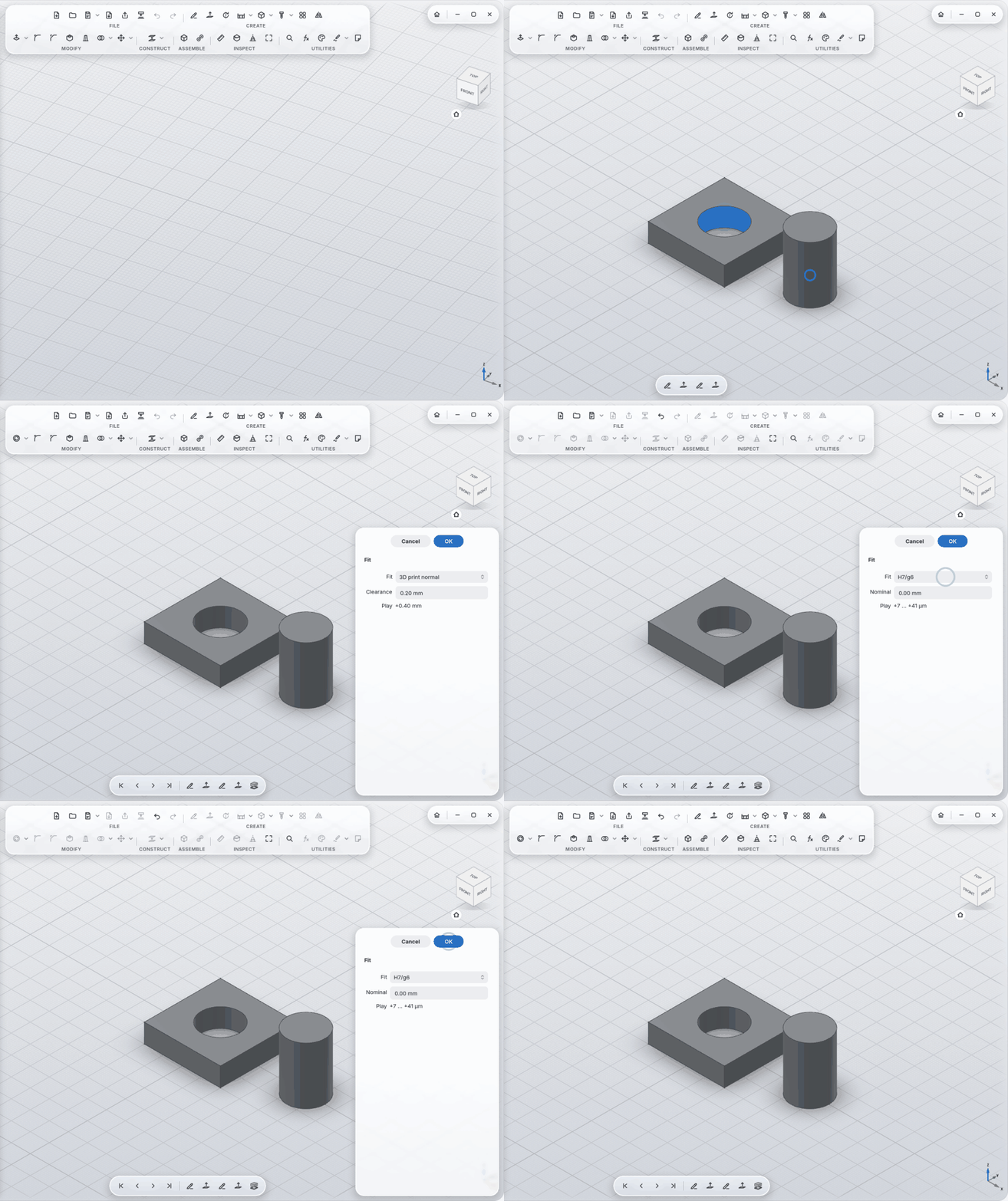
Select a hole and its pin (or flat faces), Fit (MODIFY section):
-
3D print tight / normal / loose: the hole gets wider by the play on each side (0.1 / 0.2 / 0.3 mm by default, adjustable under Settings → 3D print clearance). Without a hole, the pin gets thinner; flat faces move back.
-
ISO 286: H7/g6 (sliding), H7/h6 (close sliding), H7/k6 (transition), H7/p6 (press fit), H8/f7 (running). Both faces move to the middle of their tolerance field; the play shows in the panel, e.g.
+7 … +41 µm. -
The hole and the pin may be in two different bodies.
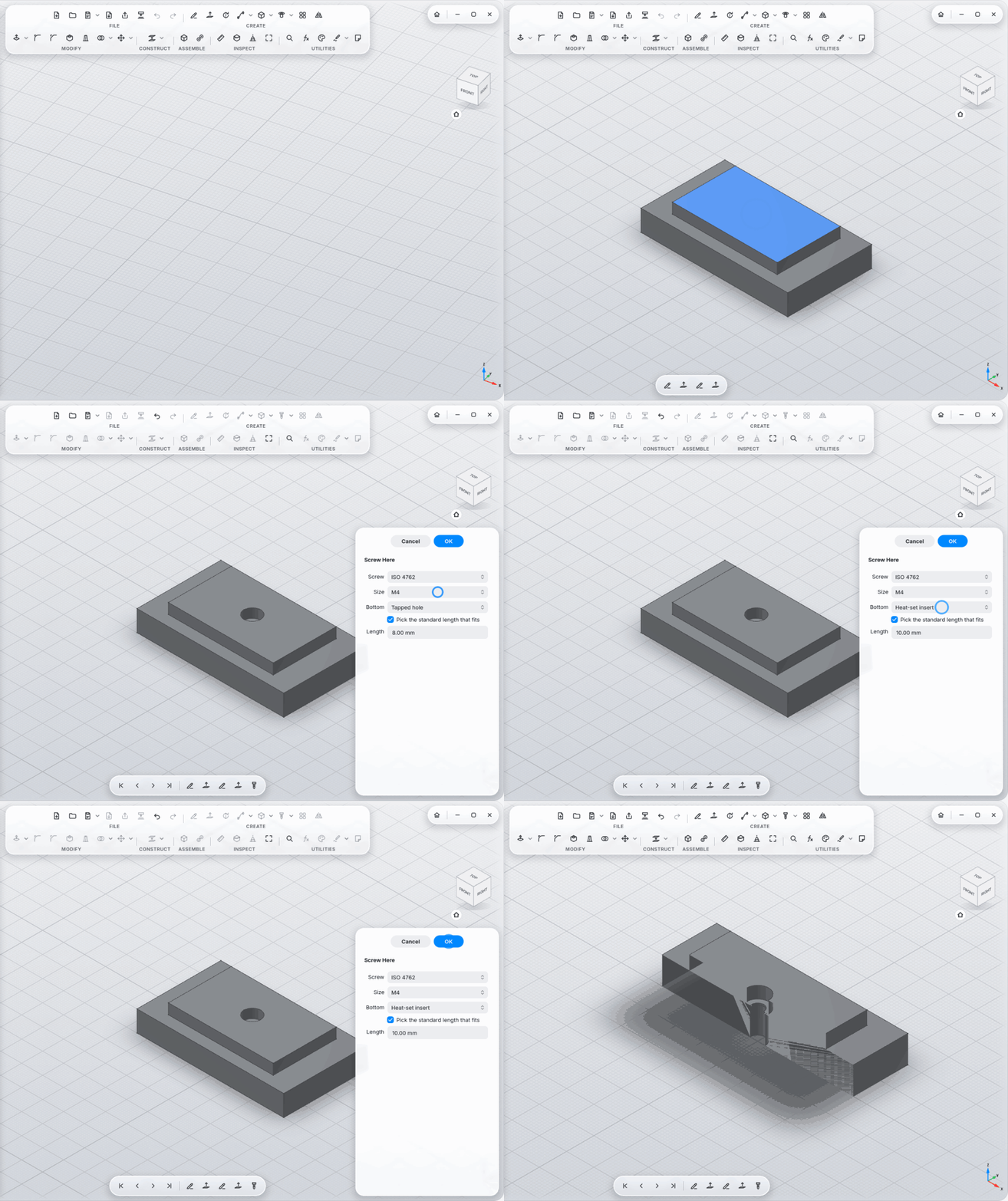
Click the top face of the upper part (or the edge of a round hole), Screw Here (arrow ▾ next to Hole). The lower part is the next body behind that point, even in another component.
-
Screw: ISO 4762 (socket head, sunk), ISO 10642 (countersunk, flush), ISO 7380 (button head); M2 to M12.
-
Bottom: Tapped hole, Heat-set insert (a hole for brass inserts, e.g. M3: Ø4 × 5.7 mm) or Nut trap (a hexagon pocket on the underside).
-
Length: the shortest standard length that holds; pick one that's too short by hand and MyCAD suggests a longer one.
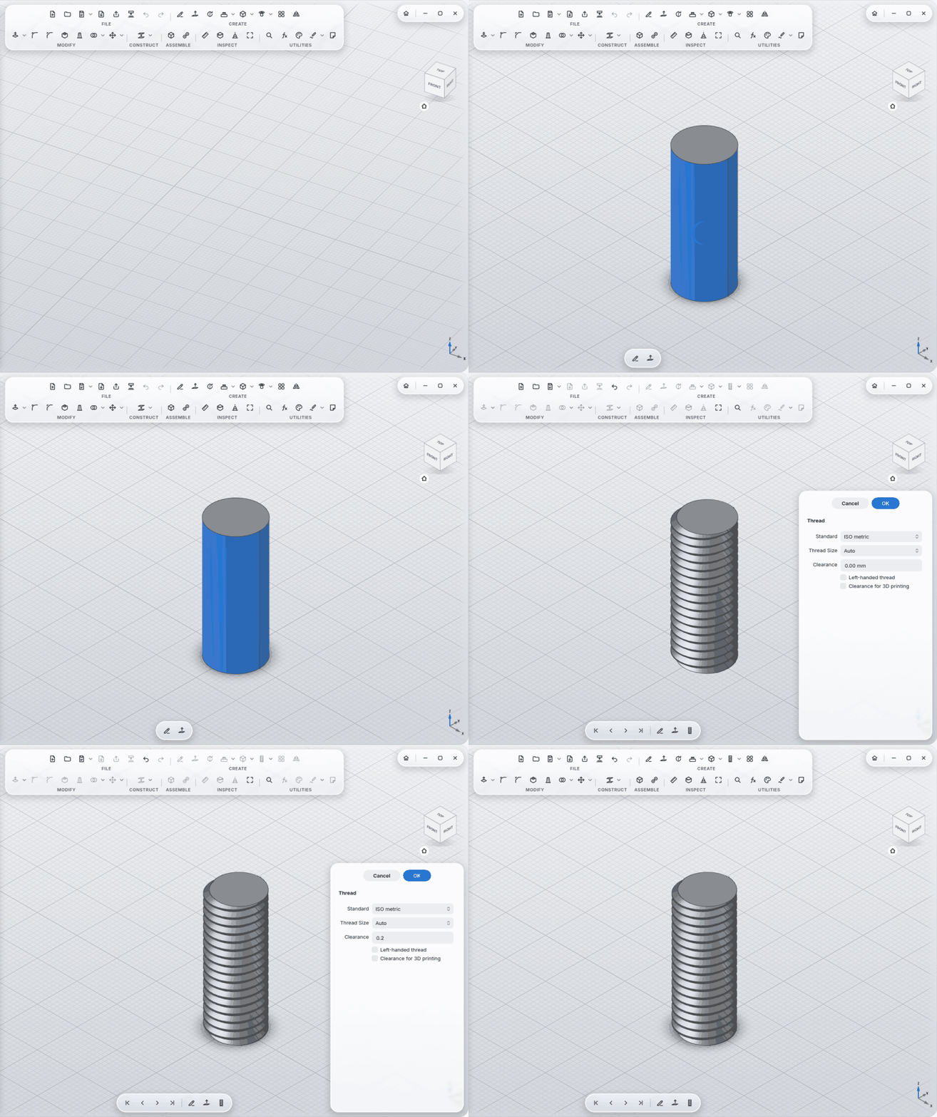
On Thread, tick "Clearance for 3D printing": the play is added automatically (at most a quarter of the pitch), and below 1 mm pitch (smaller than M8) MyCAD warns that it prints poorly with a 0.4 mm nozzle.
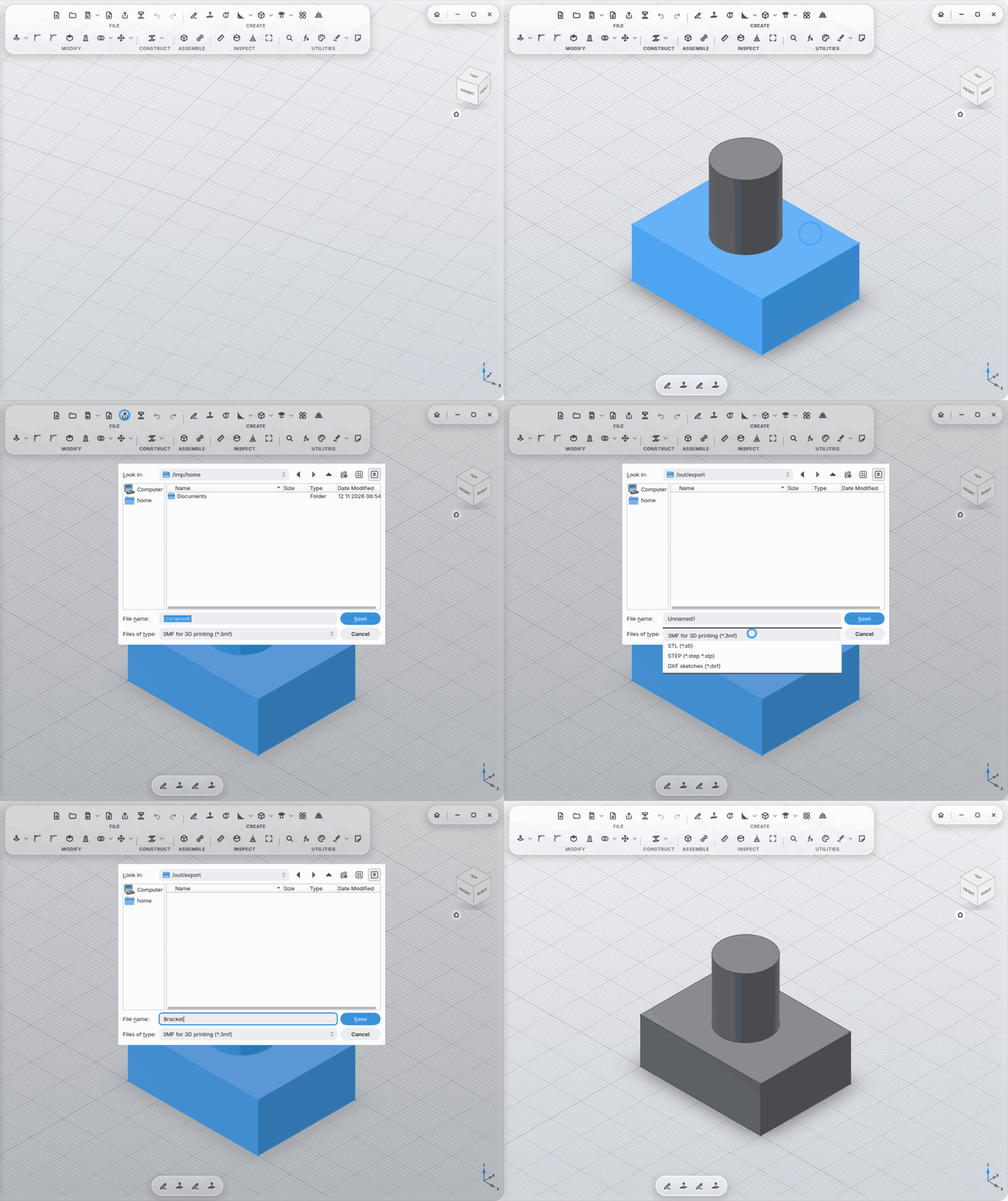
Export as 3MF (one object per body, with name and color), STL, STEP (with colors and structure) and DXF (sketches, e.g. for laser cutters and CNC).