Repository navigation
Modeling
As in Fusion 360: a sketch on a plane or face, click a profile, Extrude or Revolve, then keep going with tools like Fillet, Hole and Pattern. Every step lands in the timeline.
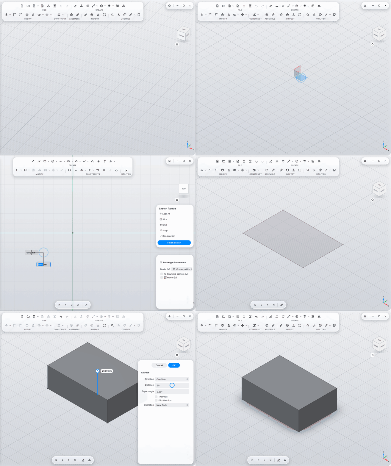
A design is made of bodies in components. The root component is the design itself; further components are for assemblies.
-
Create Sketch (S), then click a plane or flat face. The camera looks straight at it.
-
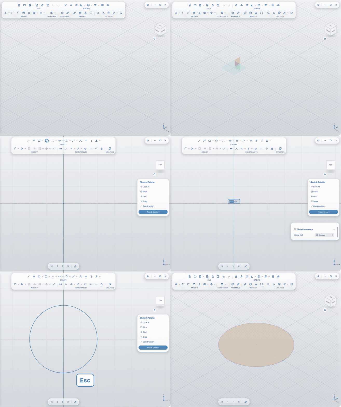
Every closed region is its own profile. Two circles inside each other give a ring and a disc.
-
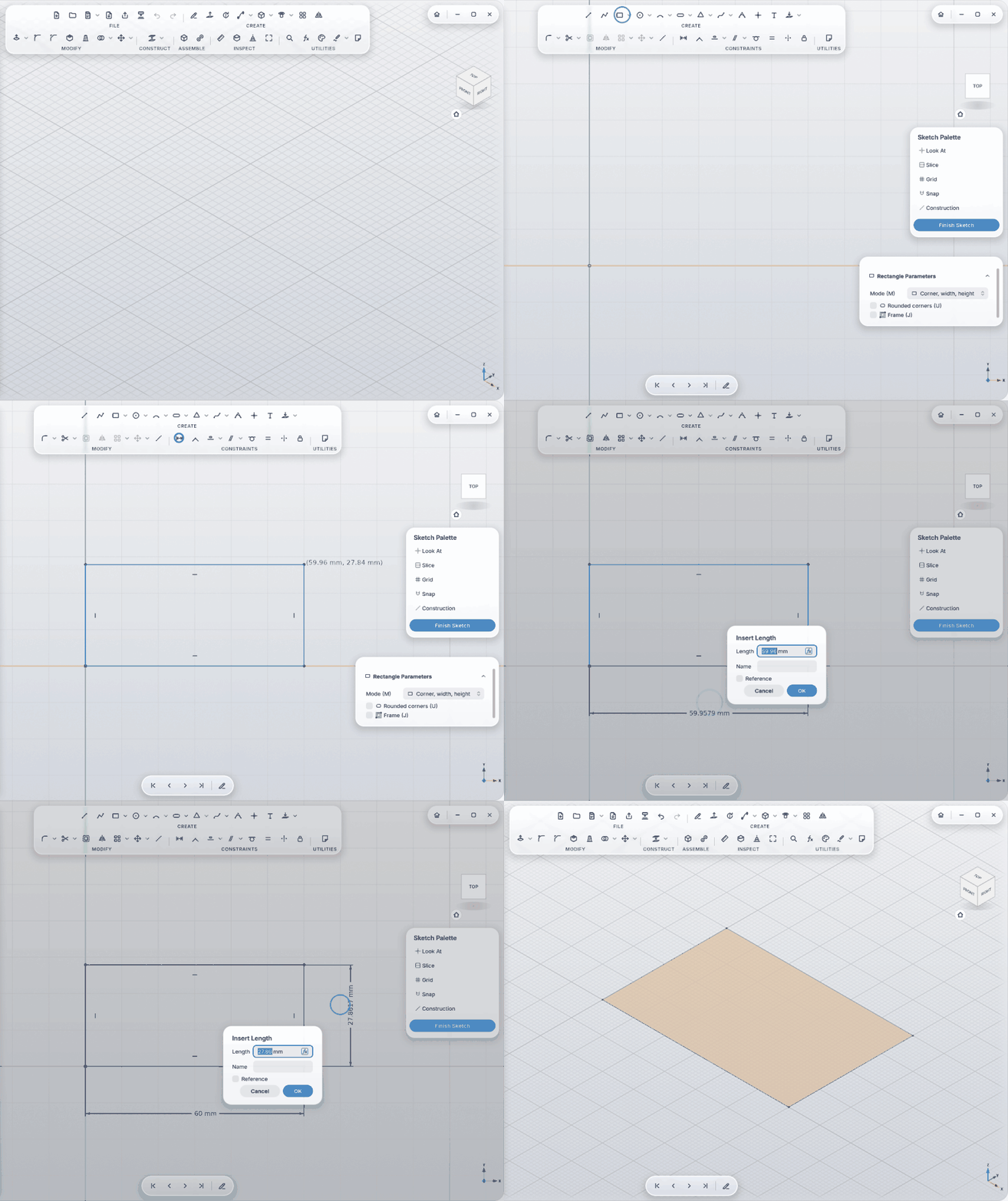
Dimension works out from the selection what to measure (length, distance, radius, angle). Place it, and a field opens right on the dimension: type the value, Enter applies, Esc keeps the old one, Tab applies and jumps to the next dimension of the sketch. Every size field takes formulas and parameter names.
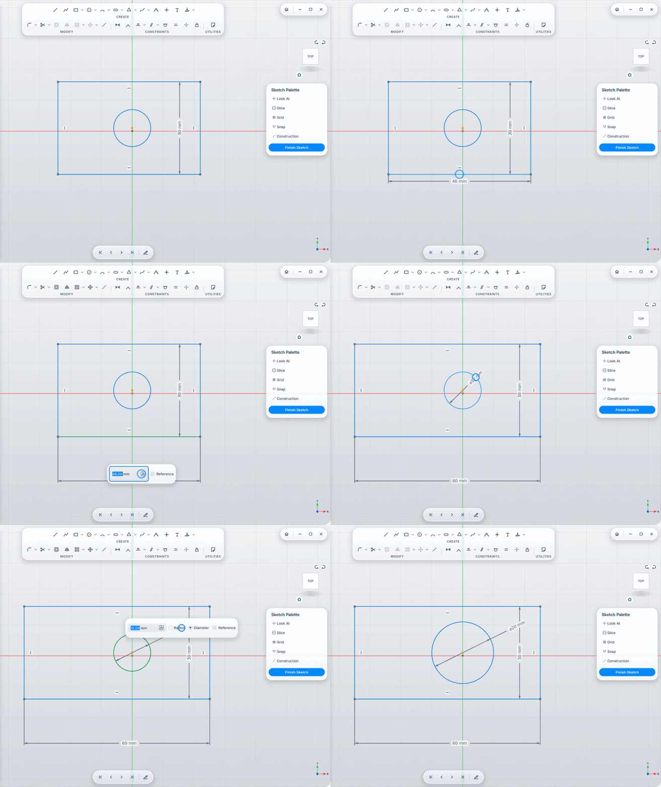
-
Esc puts the active tool away, Finish Sketch takes you back to the model.
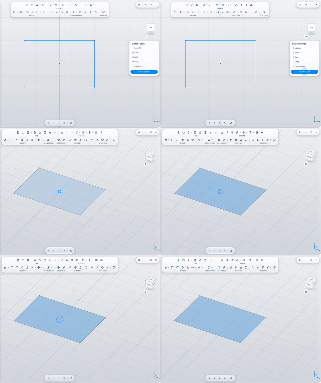
-
Edges of the model can be projected into the sketch and reused.
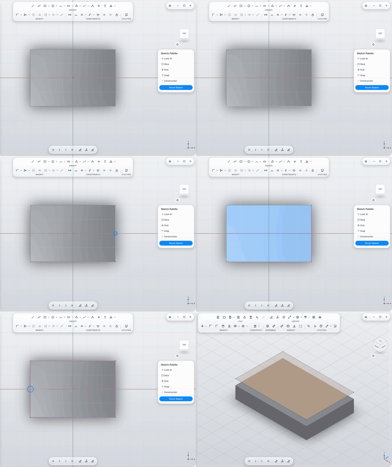
-
The Sketch Palette on the right: Look At turns the view straight onto the sketch again, Slice cuts away what lies in front of the sketch plane, Grid and Snap switch the grid and snapping, Construction draws helper lines, and the blue Finish Sketch leaves the sketch. One row says how many dimensions are missing (or Fully defined); click it and MyCAD adds them by intent: symmetric when the shape is centered on the origin, then the sizes, then its distance to the origin. Show What Can Move selects what is still free.
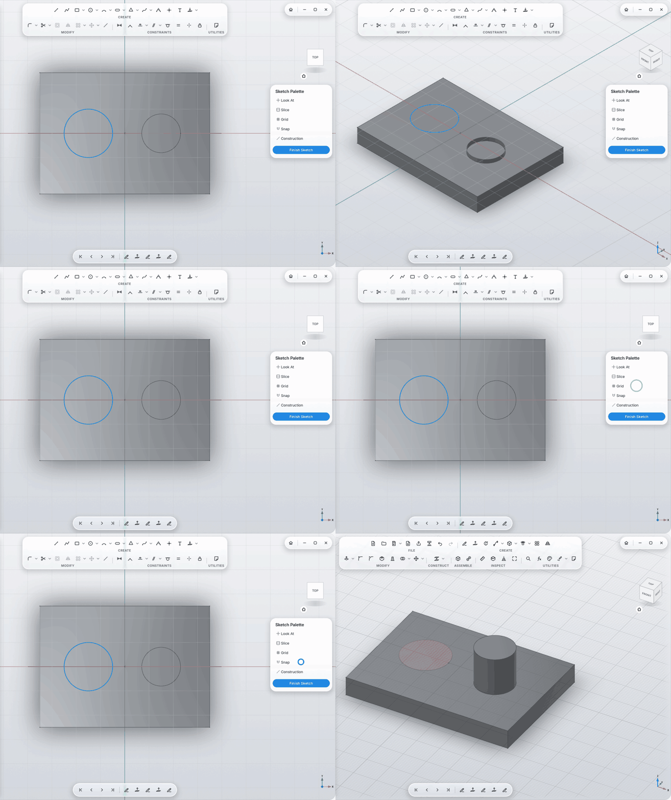
The other sketch tools:
Draw
Line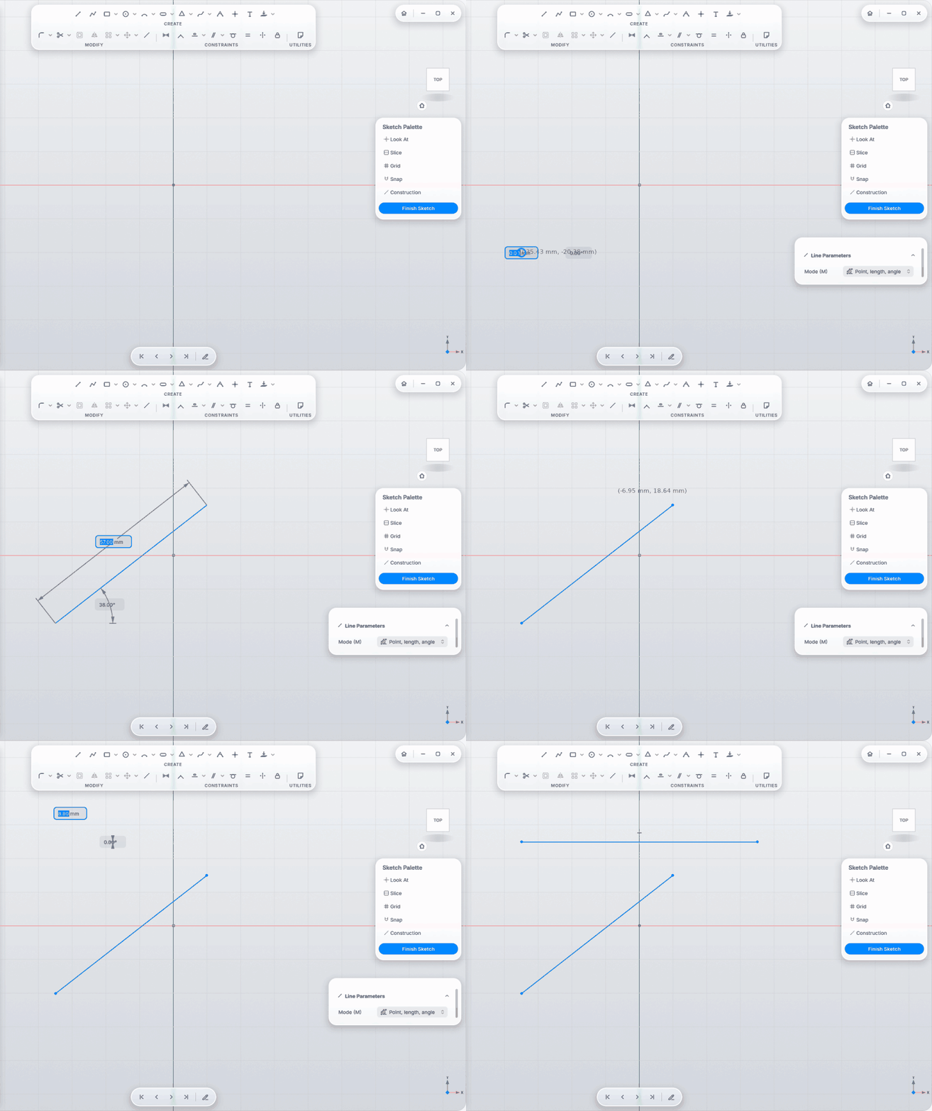
|
Polyline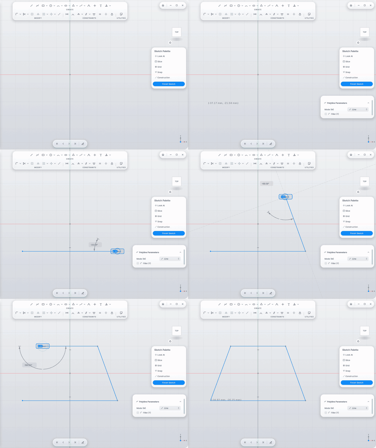
|
Rectangle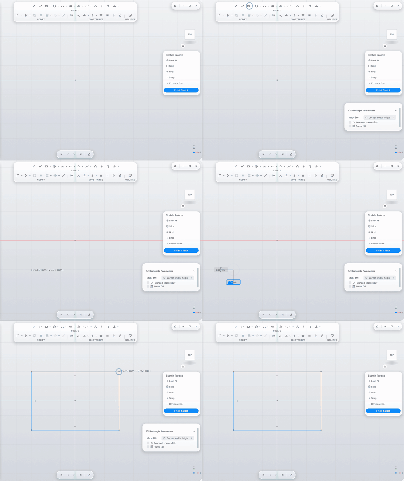
|
Circle and Ellipse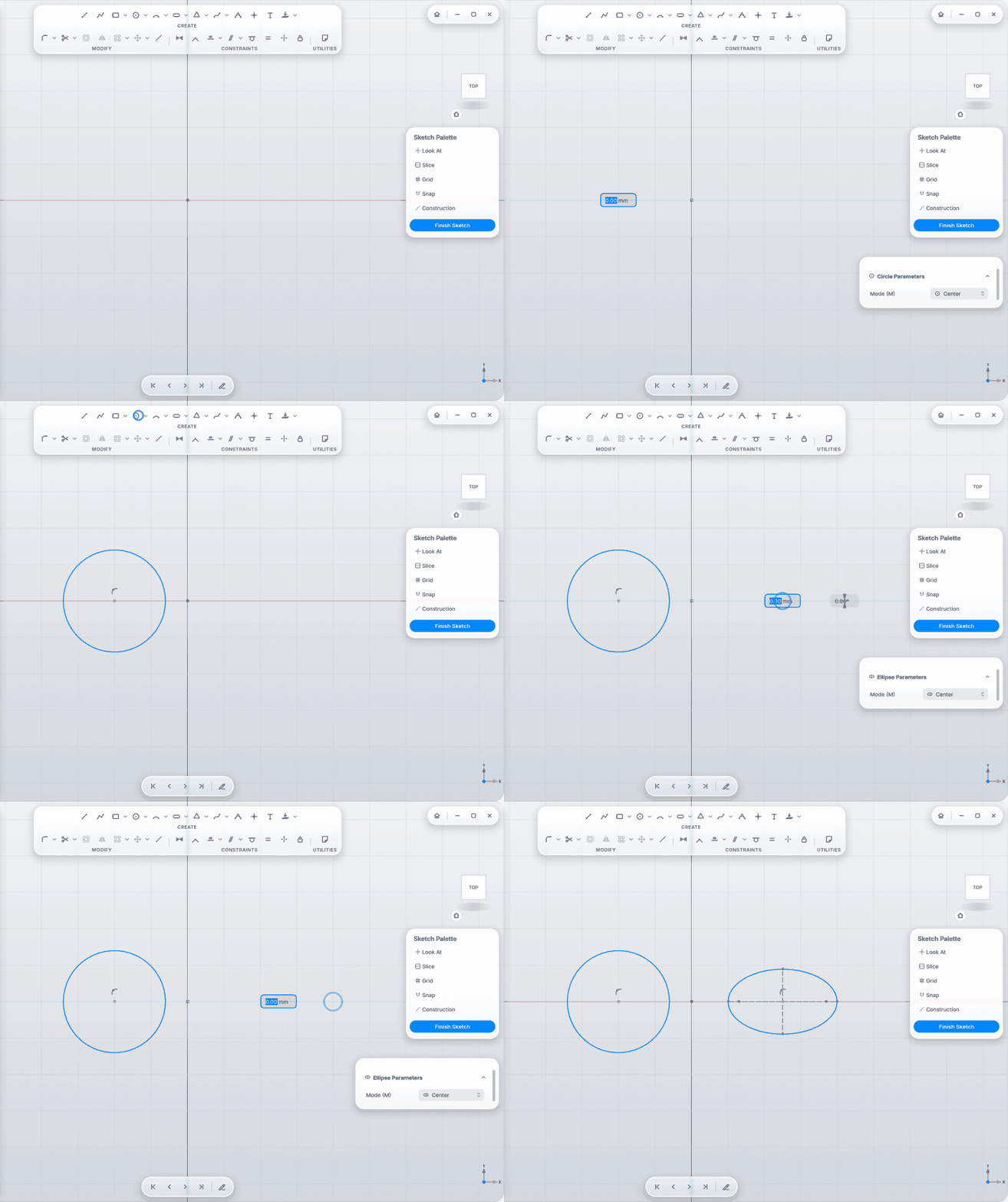
|
Arc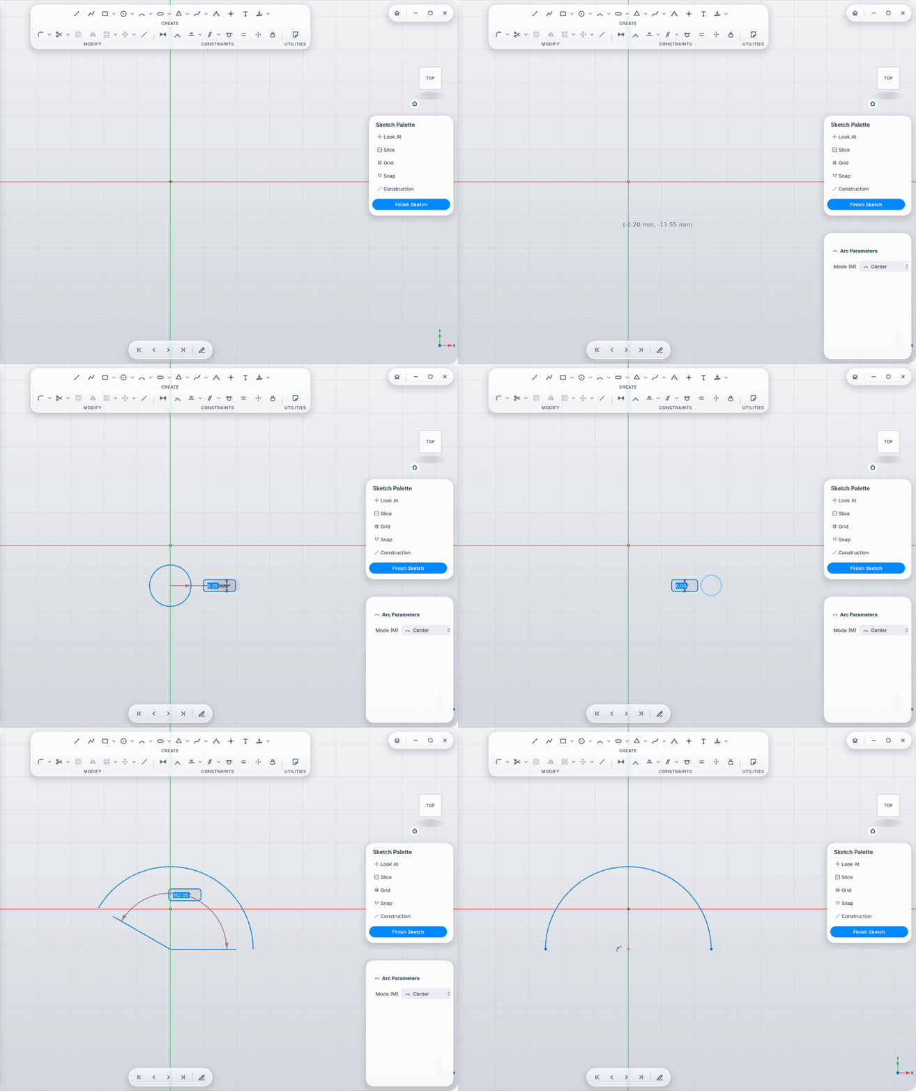
|
Slot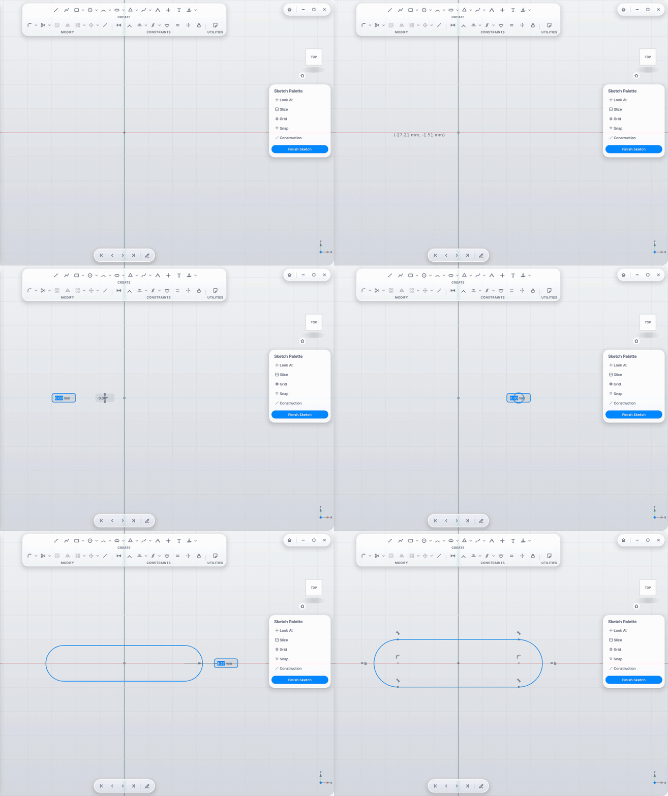
|
Polygon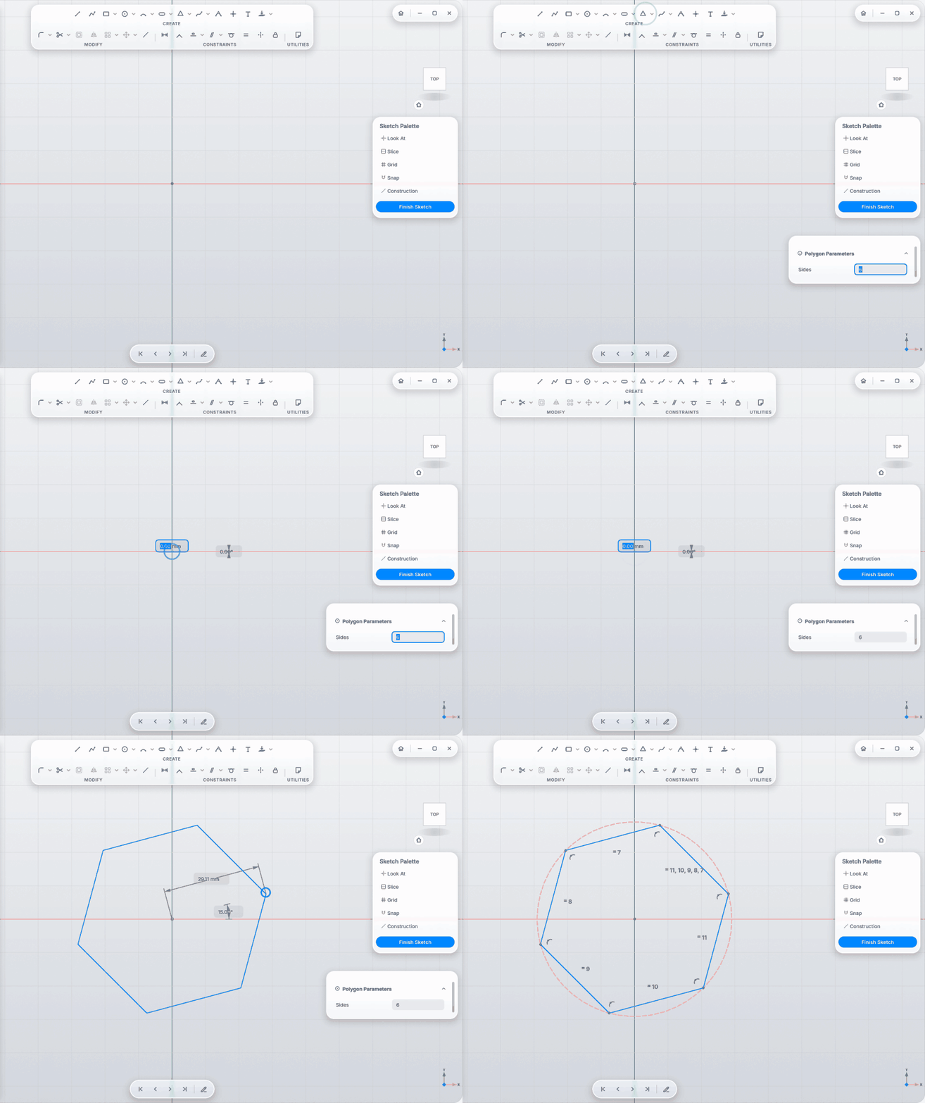
|
B-Spline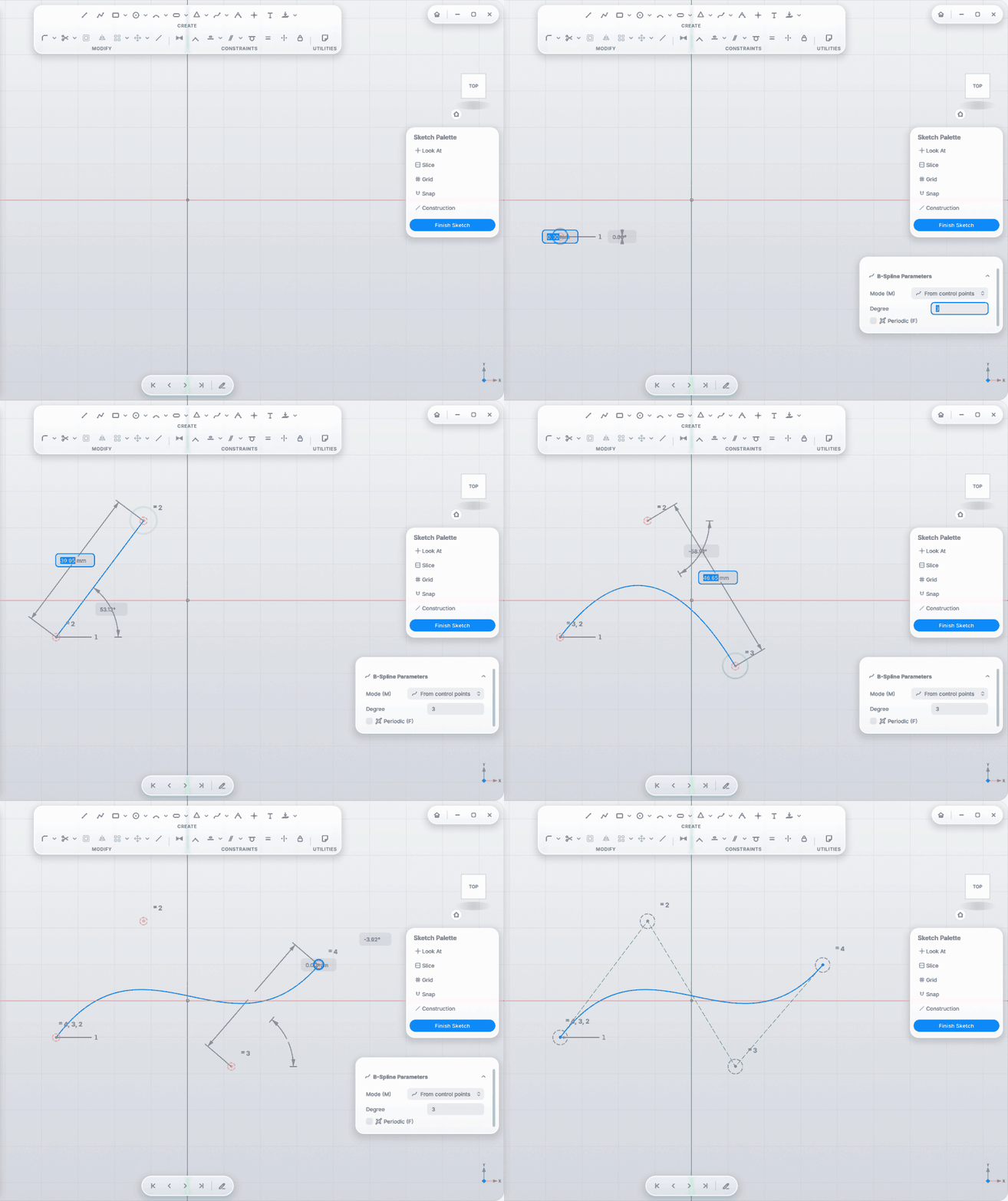
|
Conic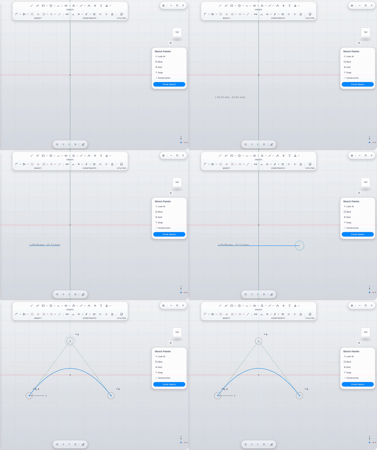
|
Point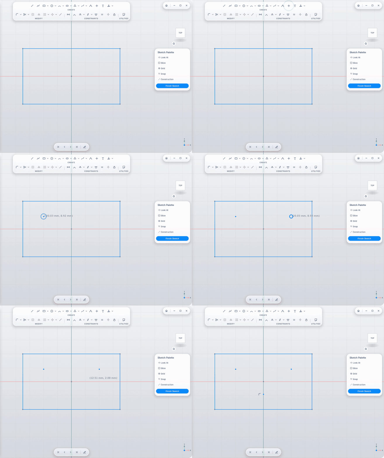
|
Text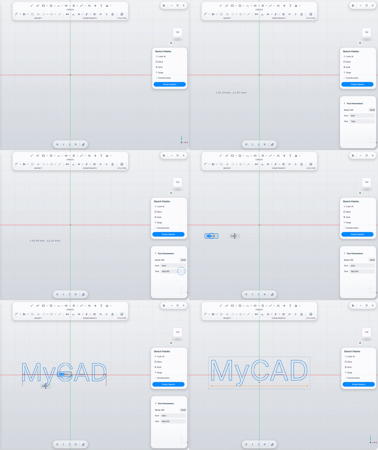
|
Modify
Sketch Fillet and Chamfer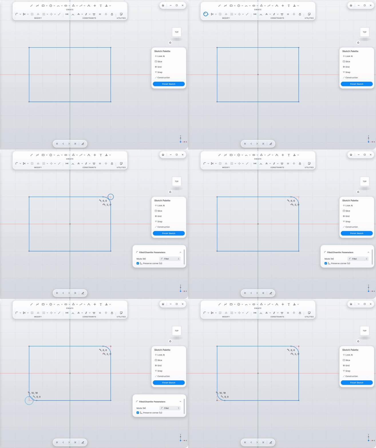
|
Trim, Extend and Split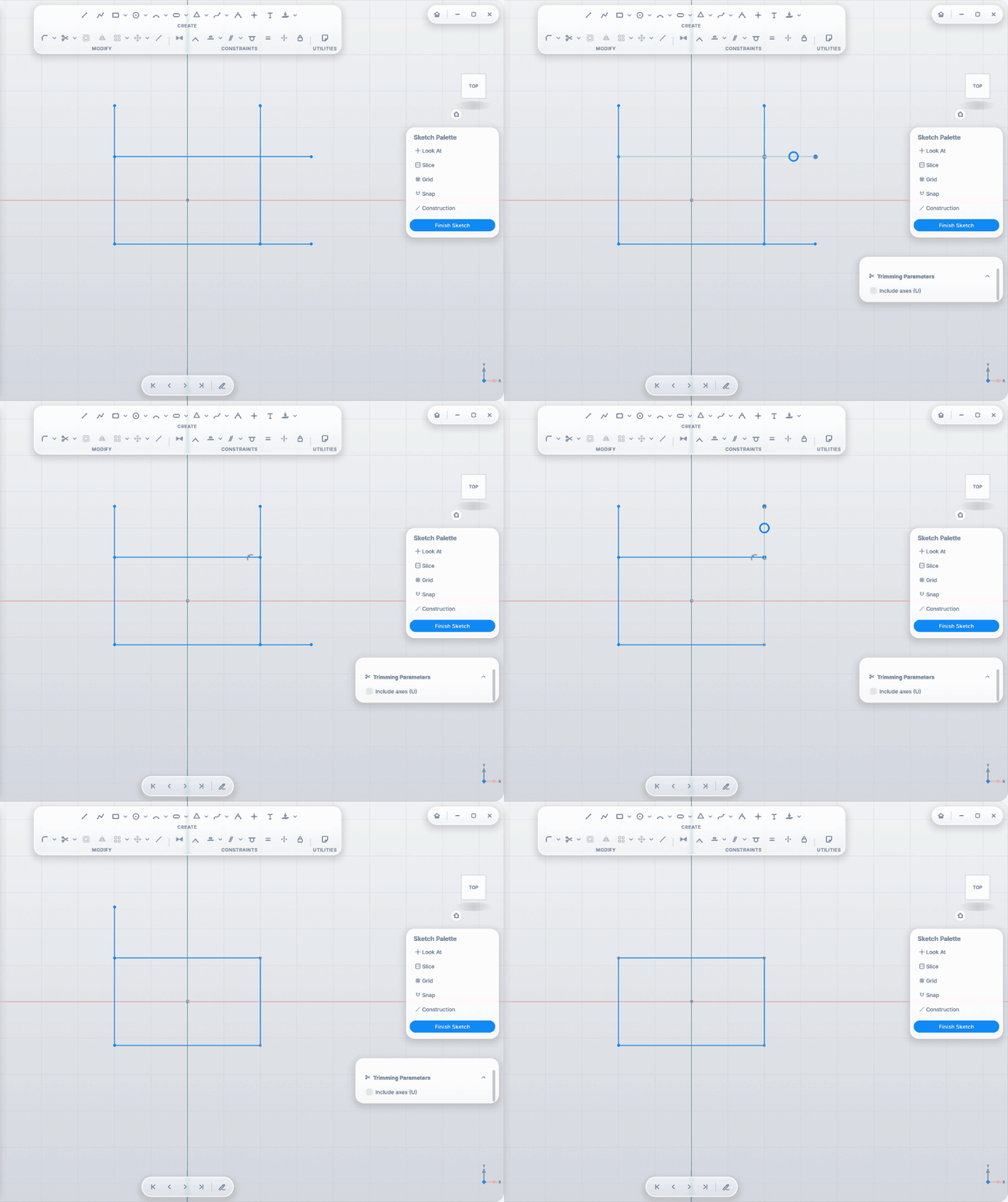
|
Offset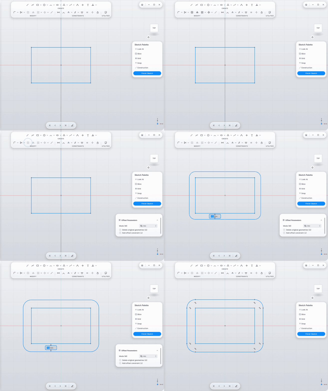
|
Mirror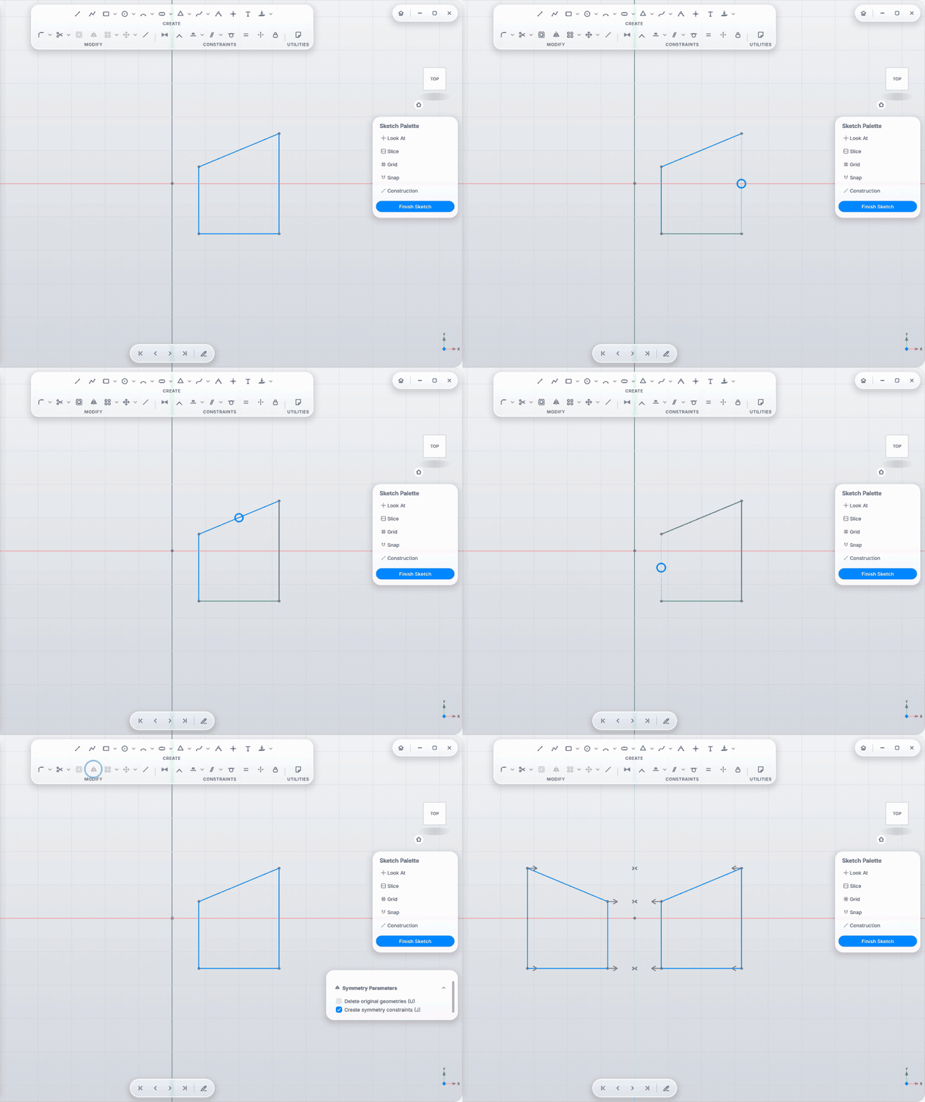
|
Pattern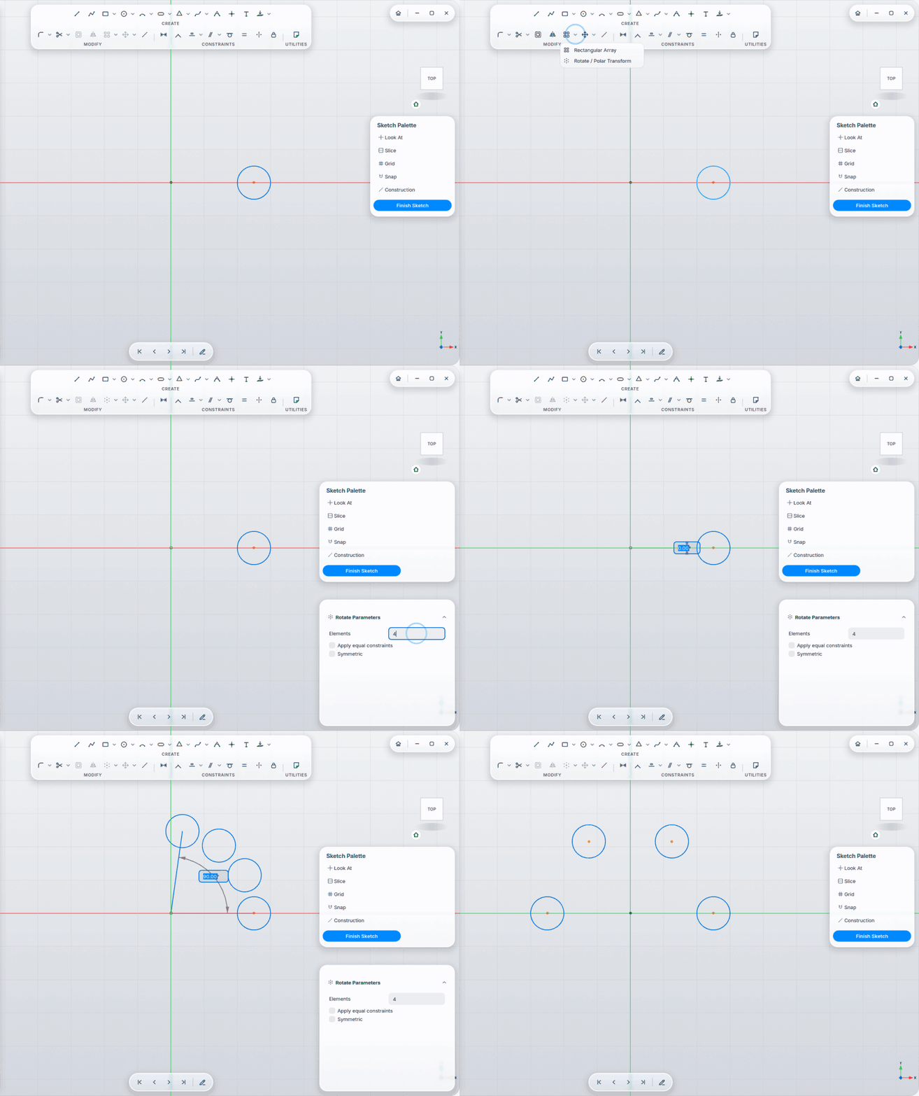
|
Move and Scale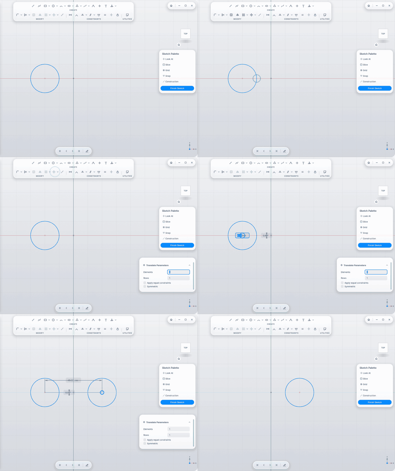
|
Construction Geometry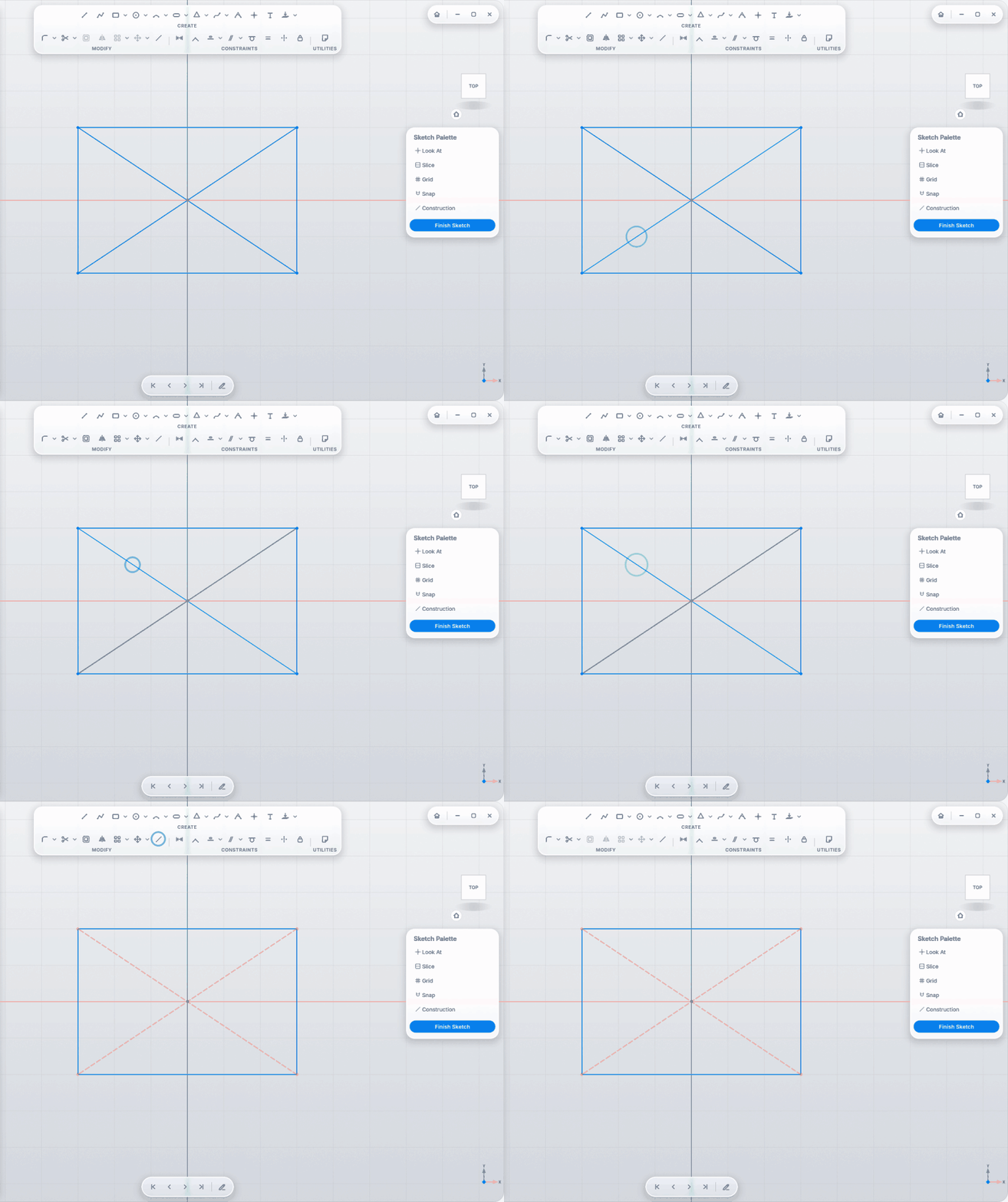
|
Constraints
Coincident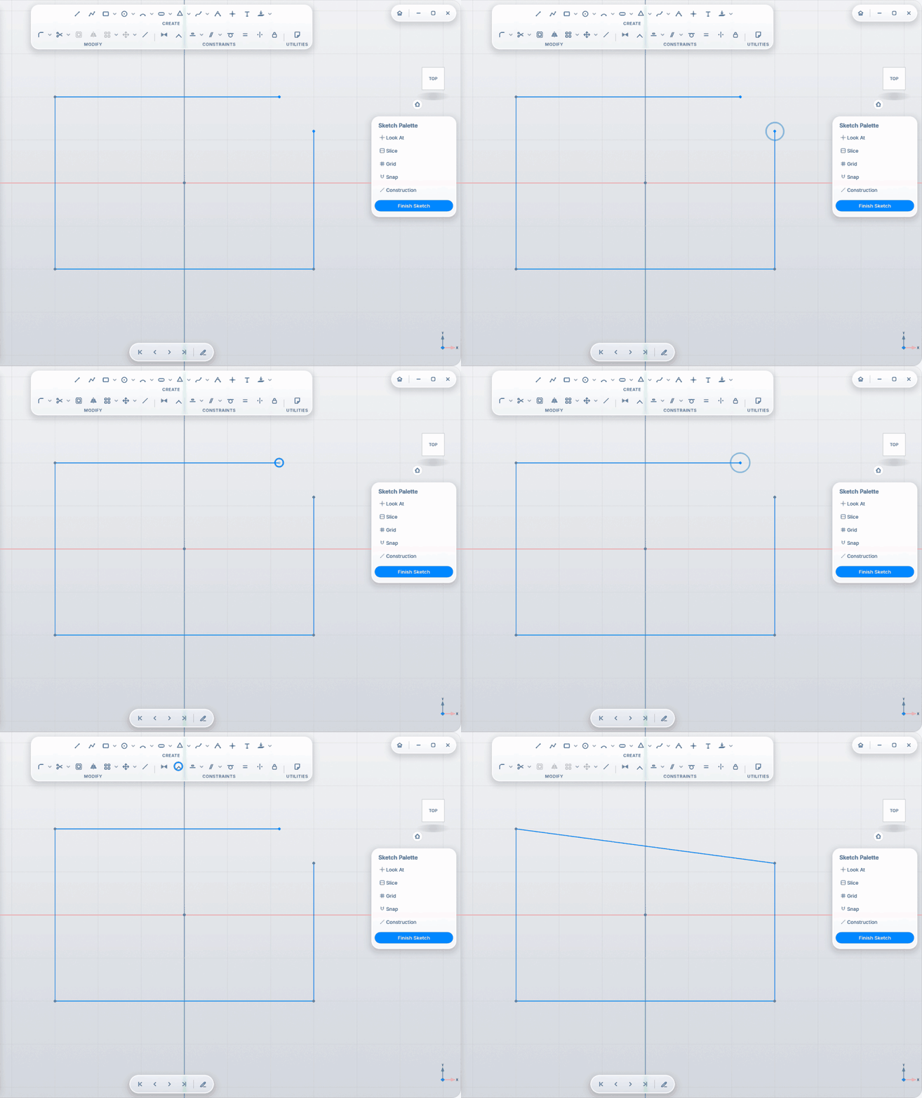
|
Horizontal and Vertical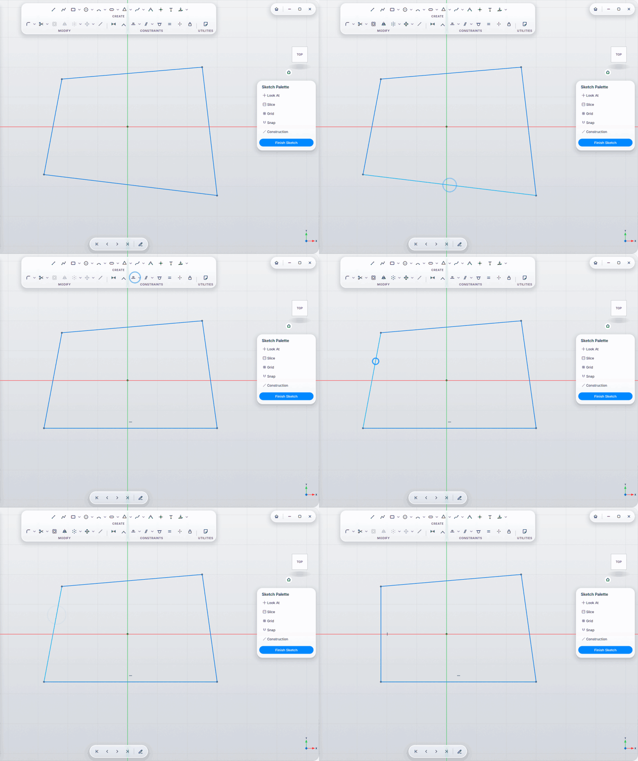
|
Parallel and Perpendicular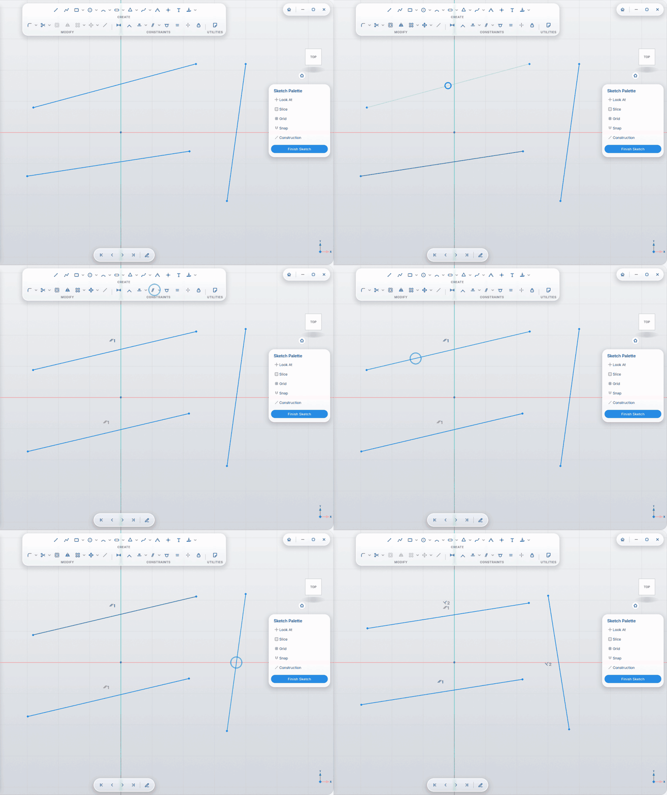
|
Tangent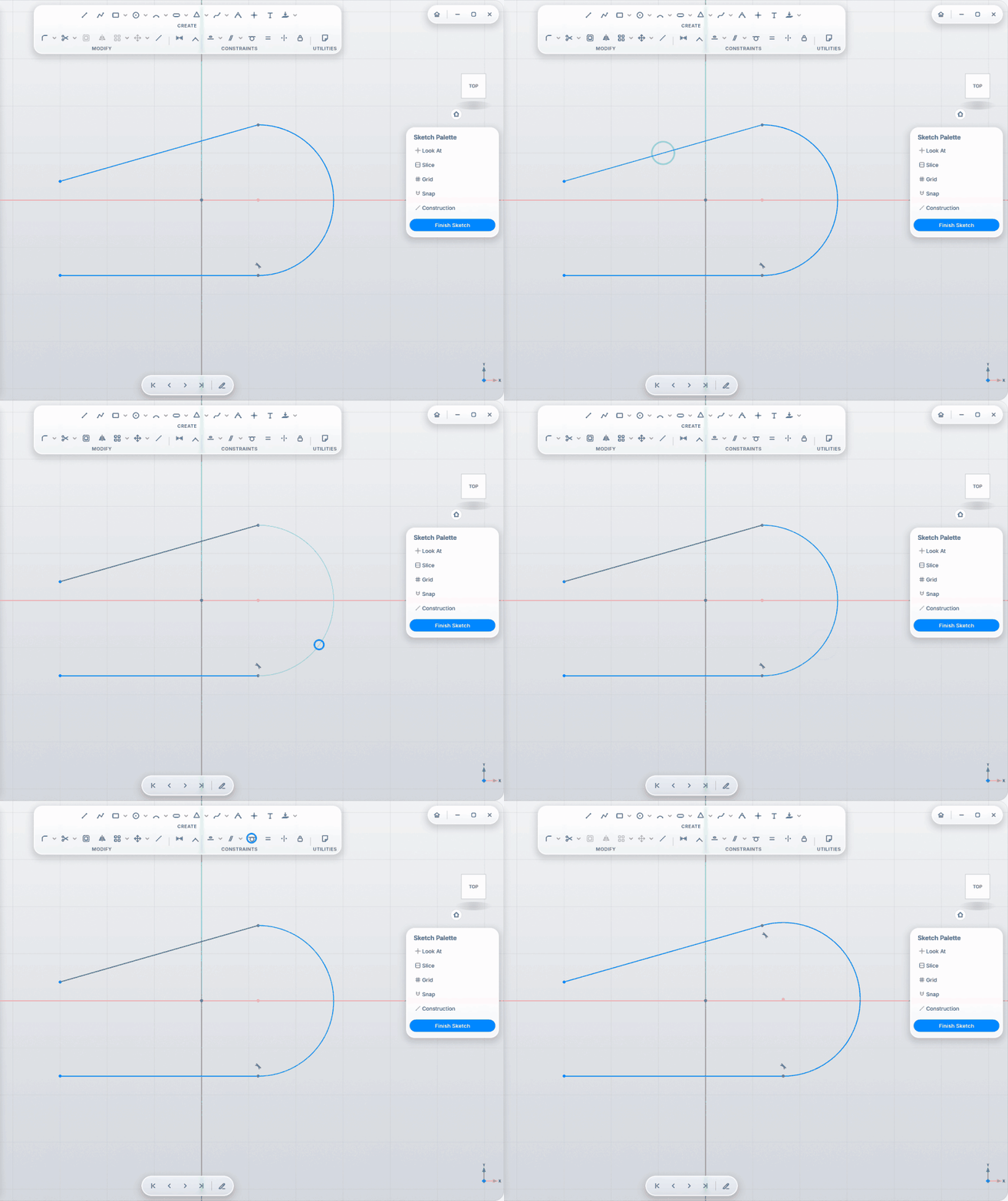
|
Equal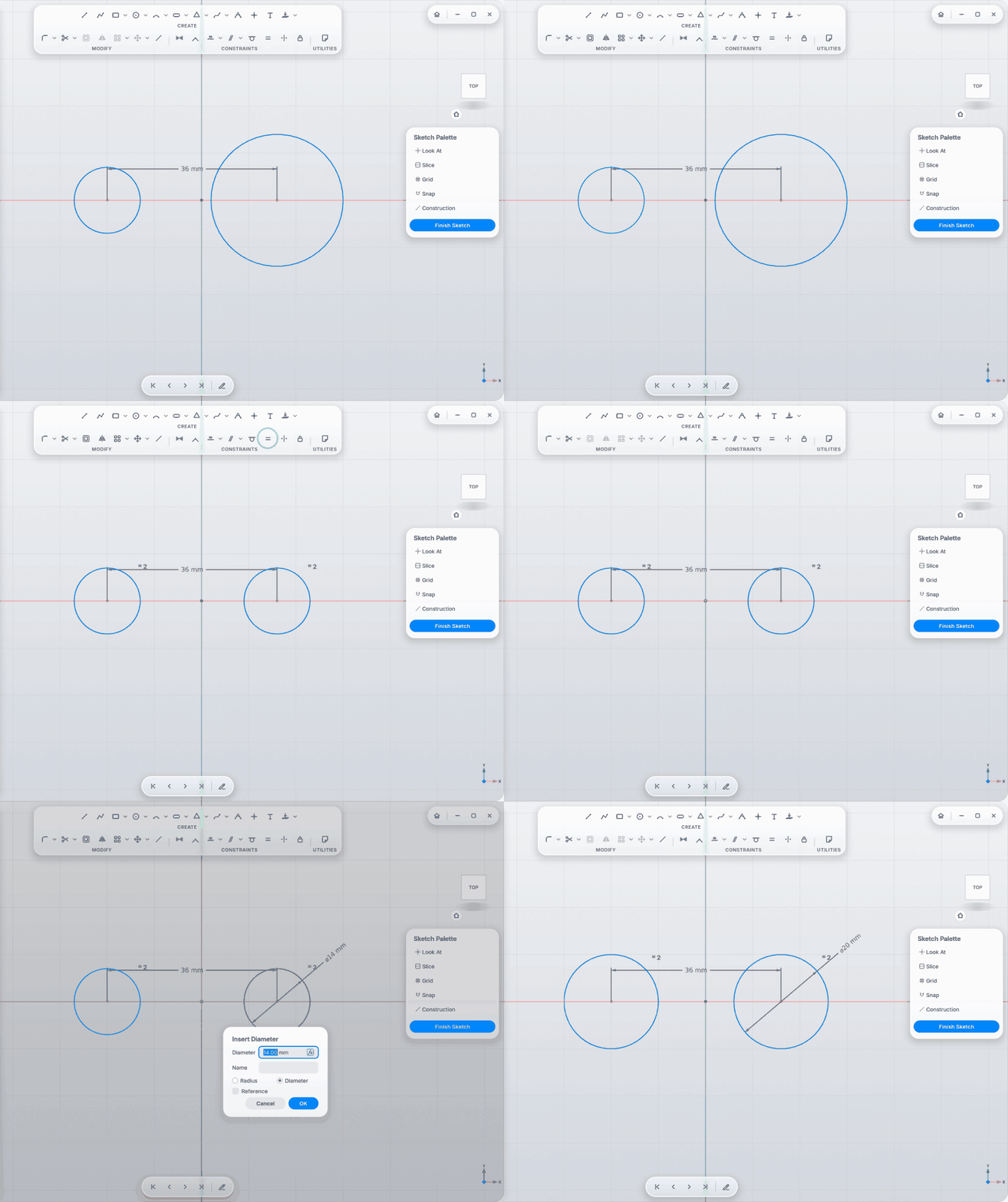
|
Symmetric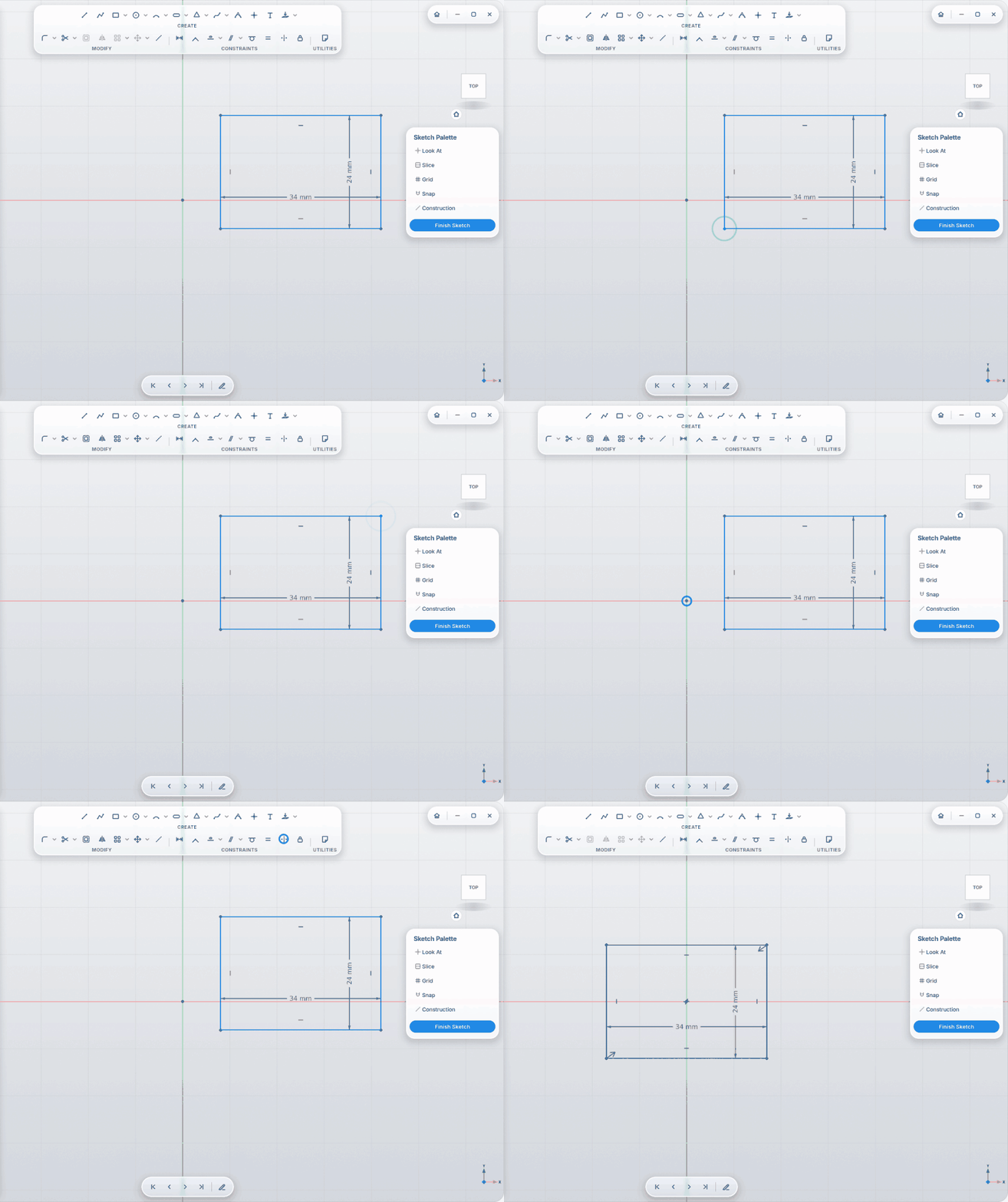
|
Block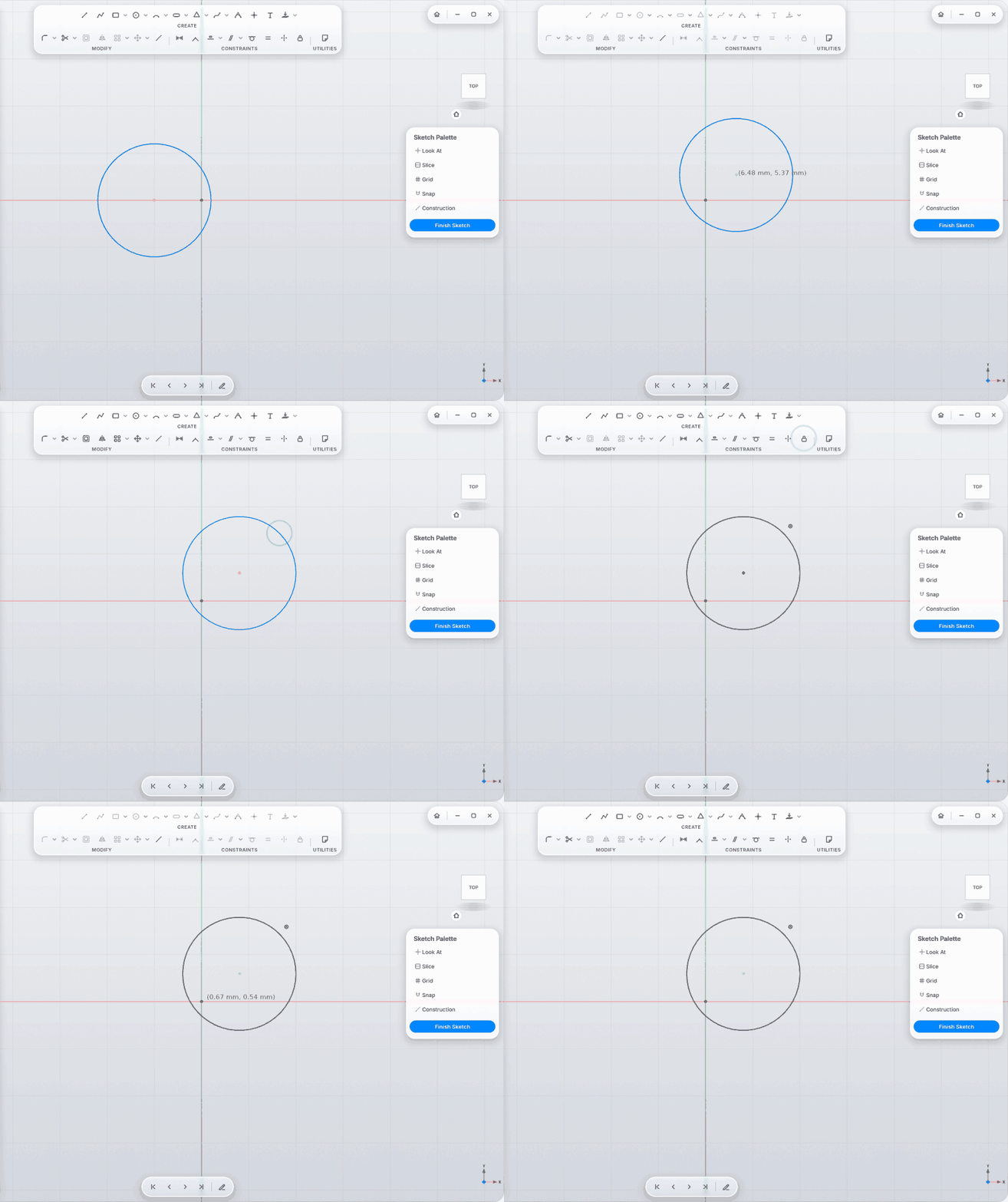
|
| Section | Tools |
|---|---|
| CREATE | Sketch · Extrude · Revolve · Sweep · Loft · Rib · Web · Emboss · Box · Cylinder · Sphere · Torus · Coil · Hole · Screw Here · Thread · Pattern · Mirror |
| MODIFY | Press Pull · Fit · Remove Face · Replace Face · Split Face · Fillet · Chamfer · Shell · Draft · Combine · Split Body · Move · Align · Scale |
| CONSTRUCT | Offset Plane · Plane at Angle · Midplane · Plane · Axis · Point |
Align and Midplane stay true to what you picked: an aligned body follows its target when that moves or grows, a midplane stays in the middle when one of its two faces moves. | ASSEMBLE | New Component · Joint | | INSPECT | Measure · Section Analysis · Print View · Fit All | | UTILITIES | Search · Change Parameters · Appearance · Scribble / Red Pen · Note |
Buttons with a small arrow ▾ hold more tools (for example Hole ▾ Screw Here, Thread).
The other tools in short clips; the ones with more to say have their own section below.
CREATE
Revolve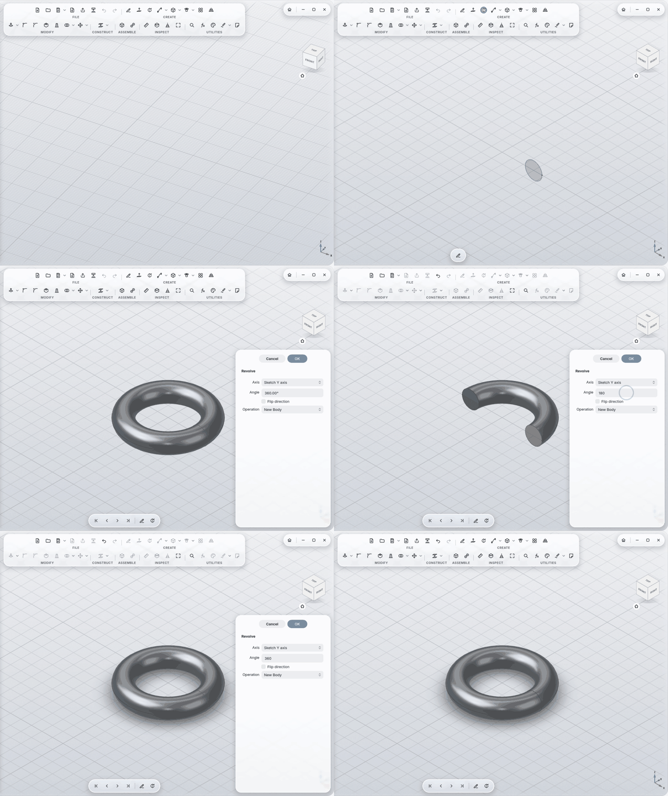
|
Sweep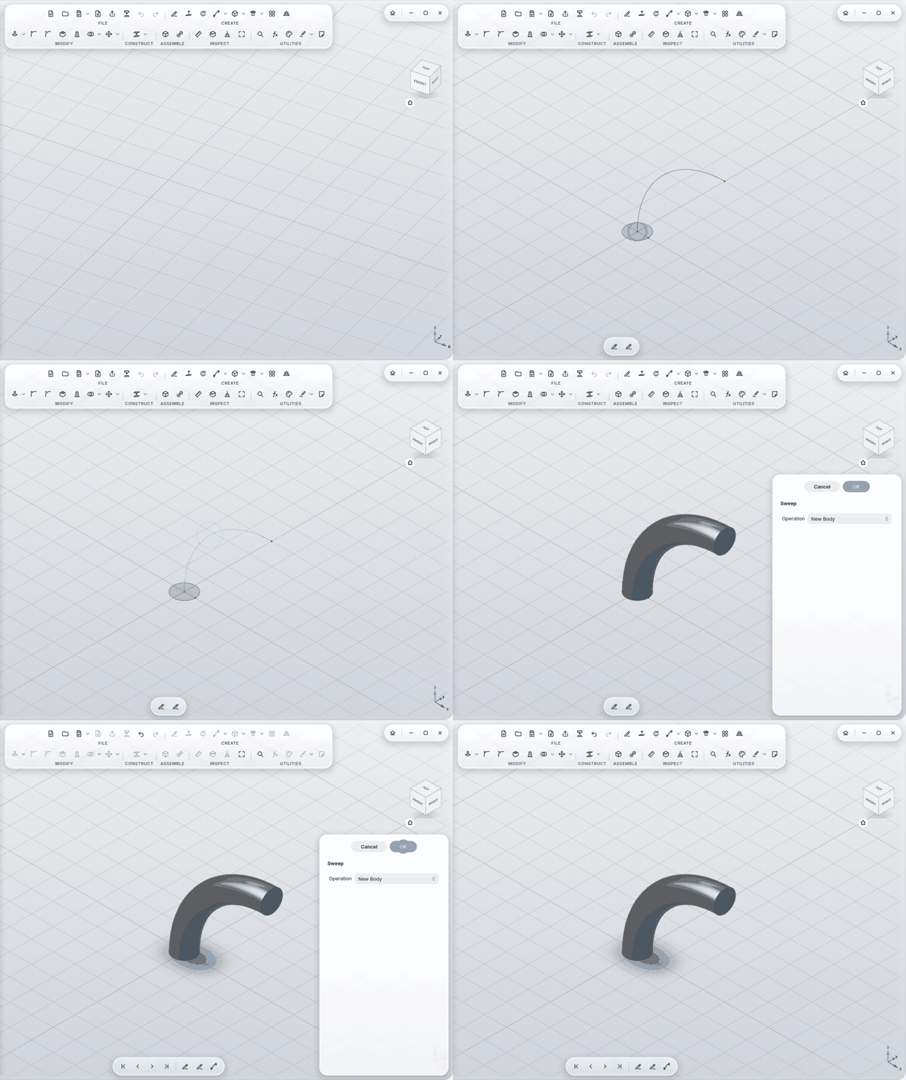
|
Loft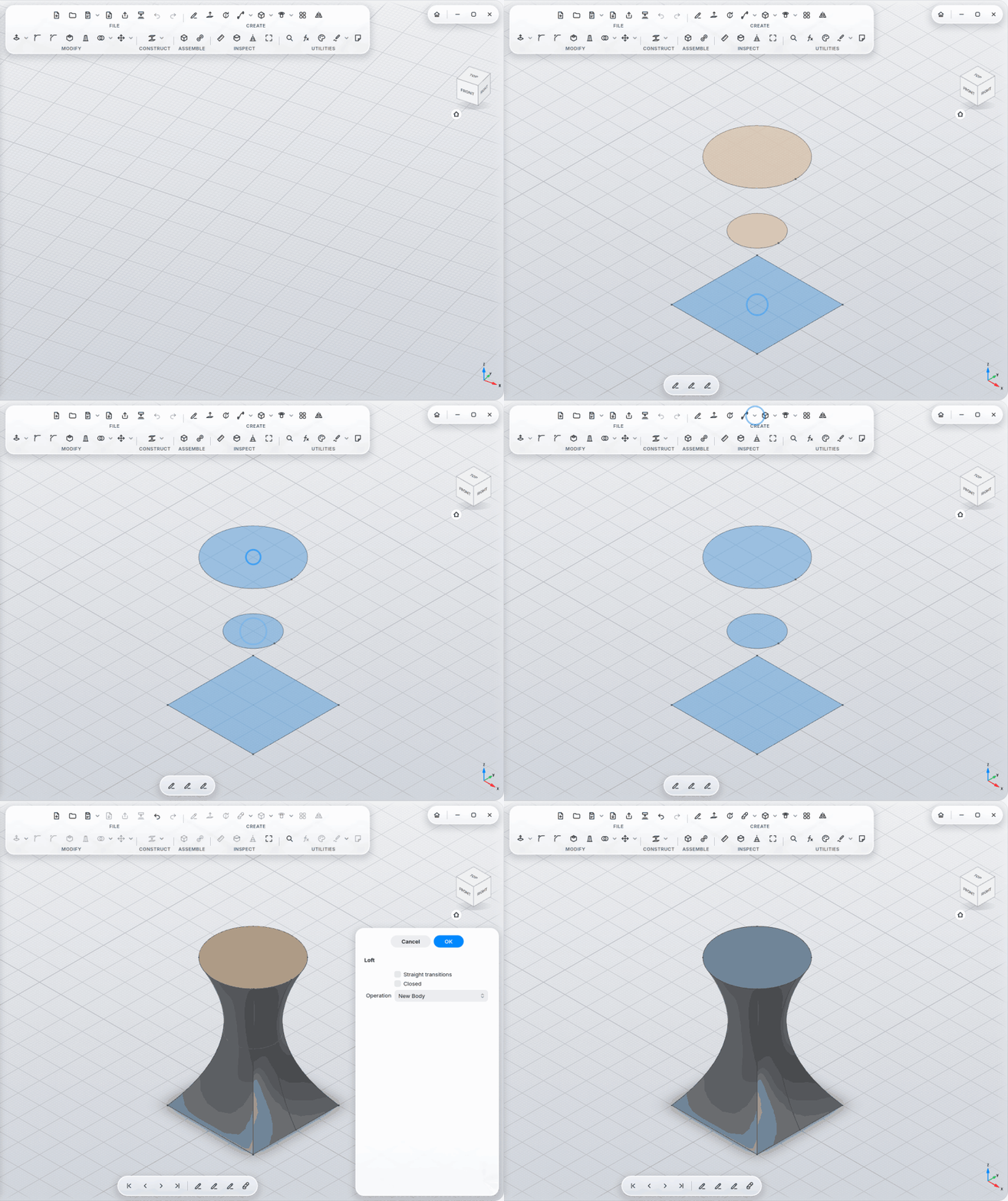
|
Rib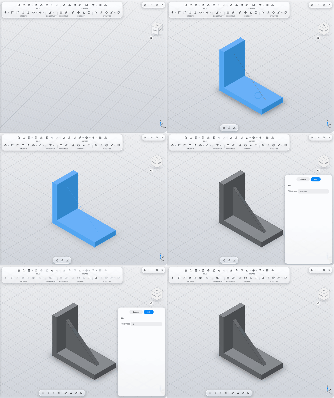
|
Web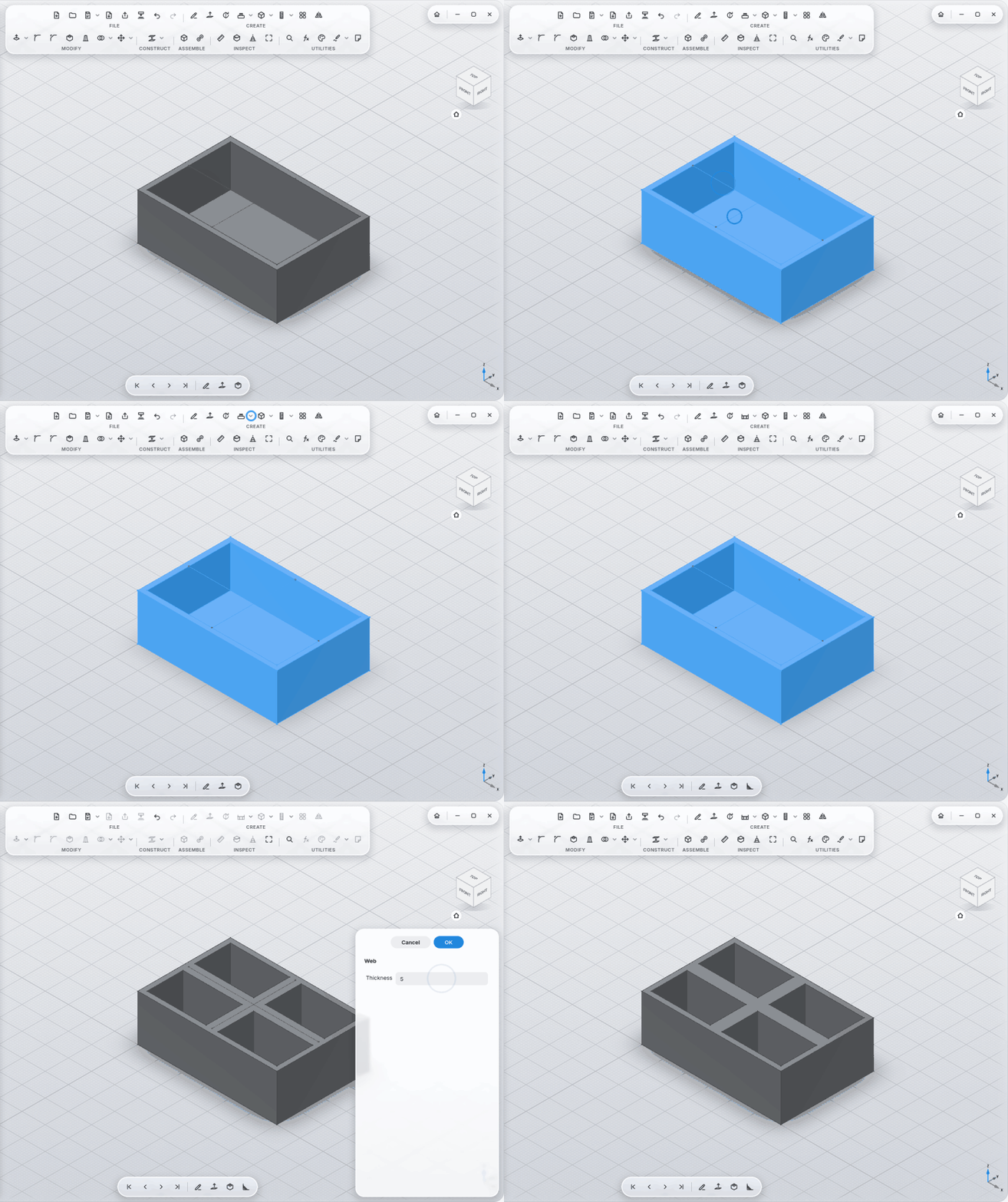
|
Emboss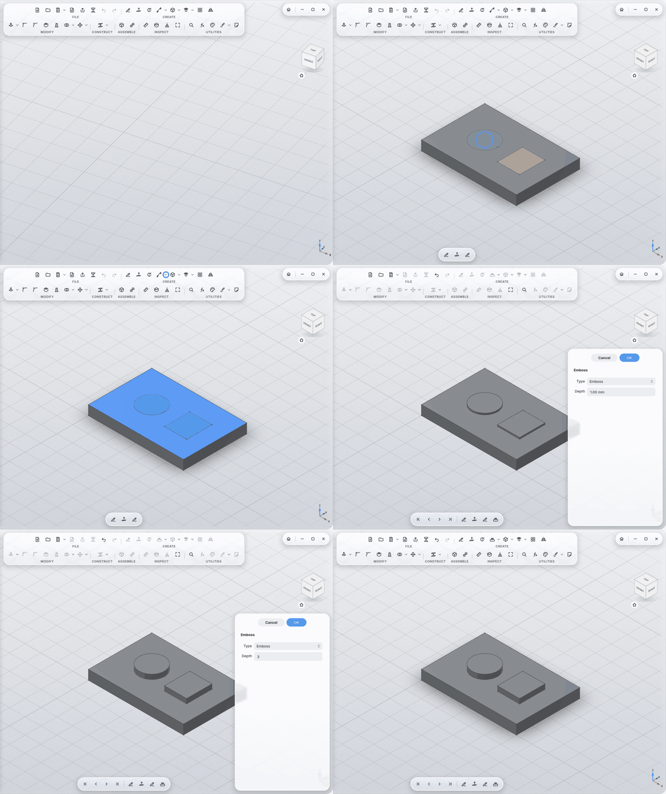
|
Box, Cylinder and more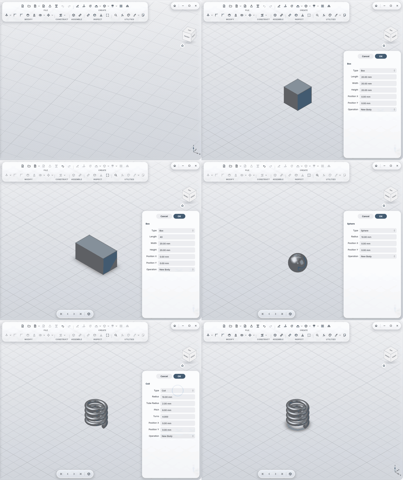
|
MODIFY
Press Pull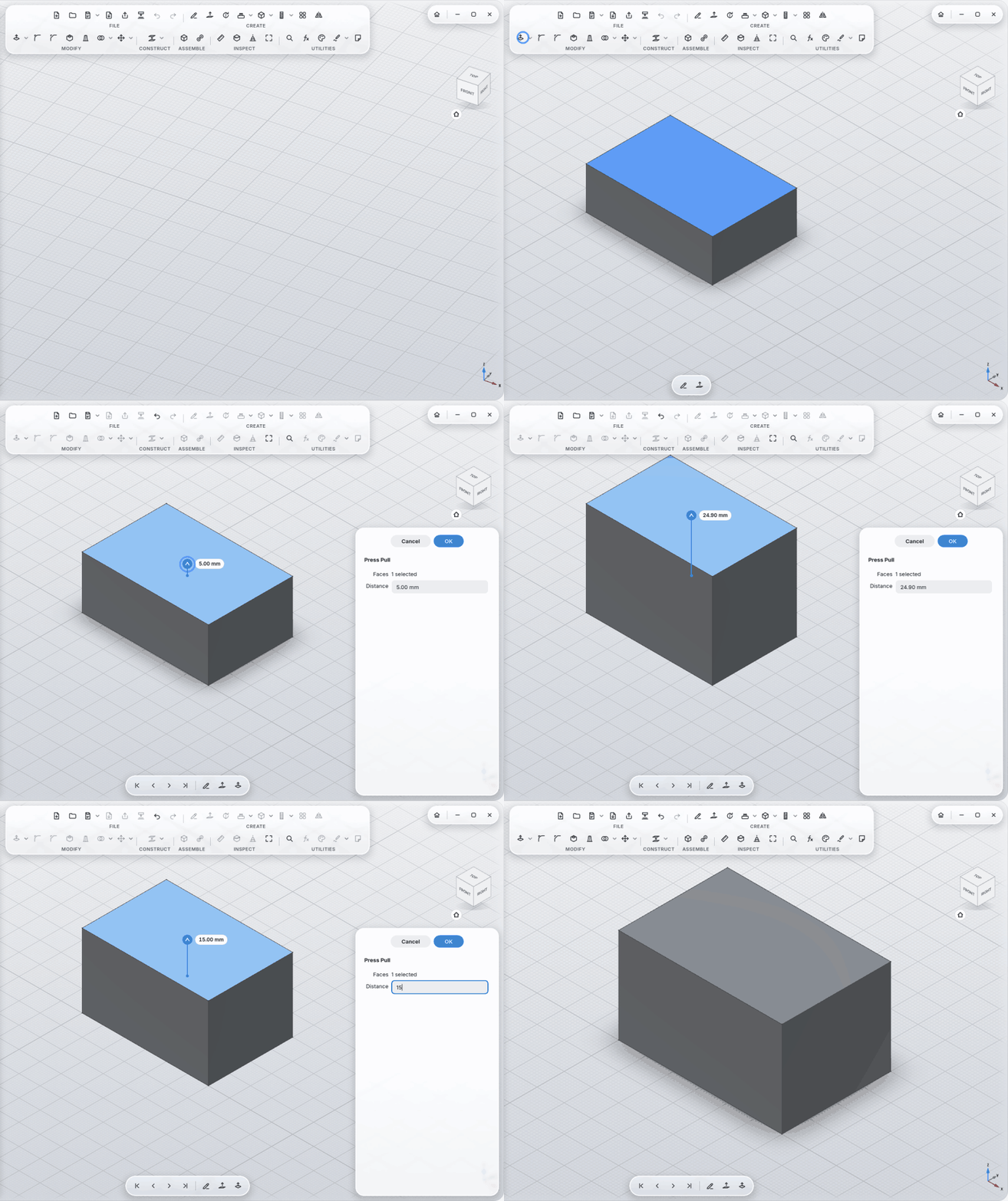
|
Replace Face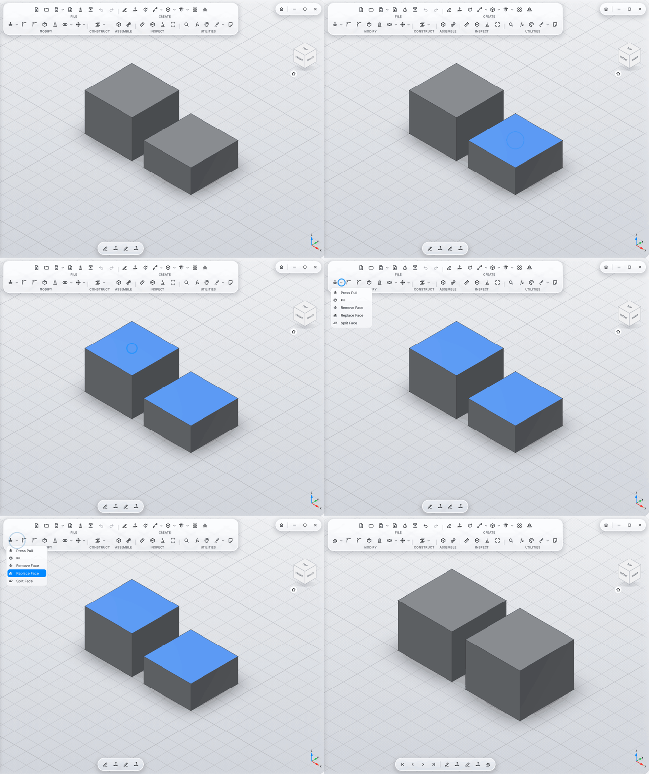
|
Split Face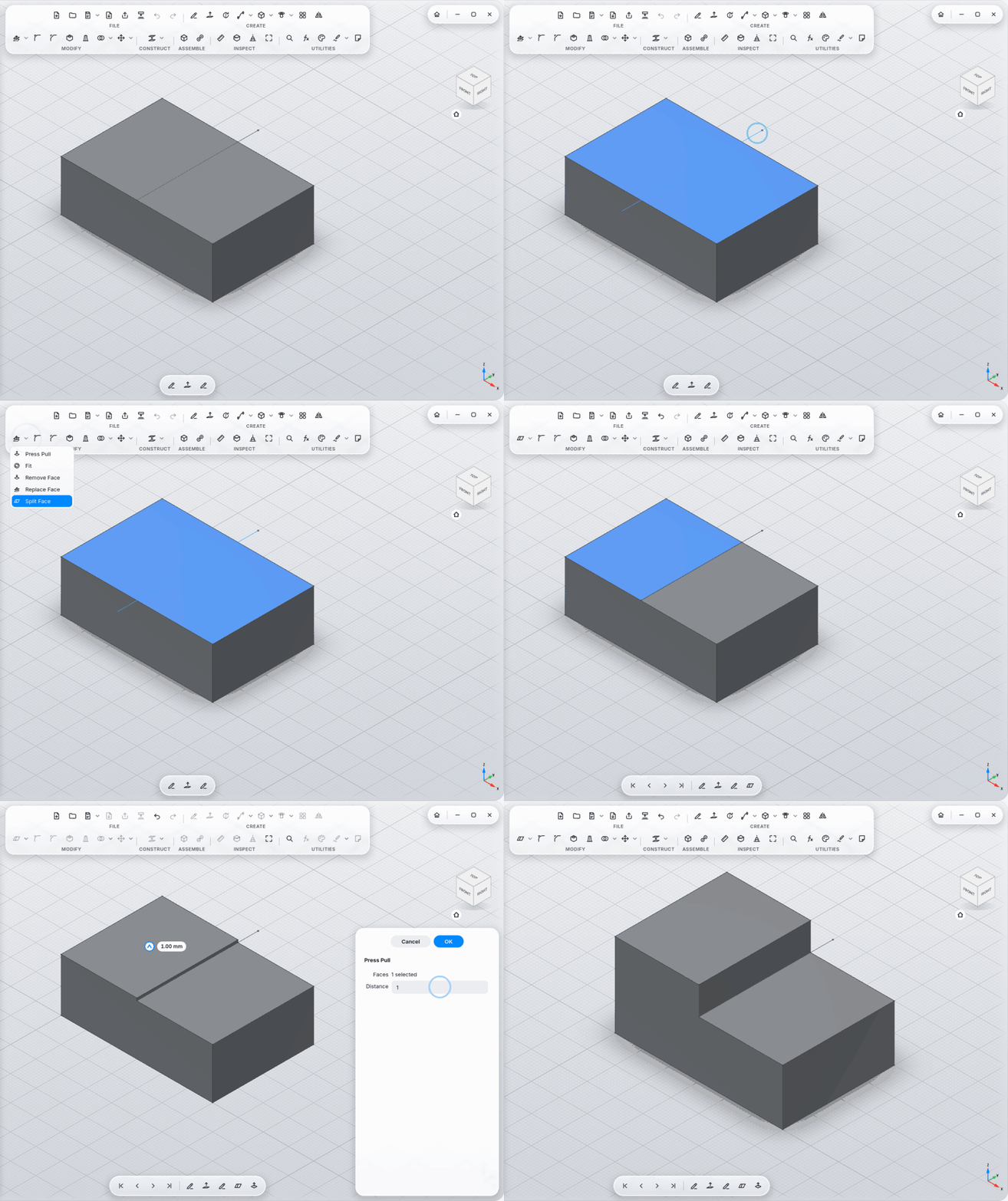
|
Draft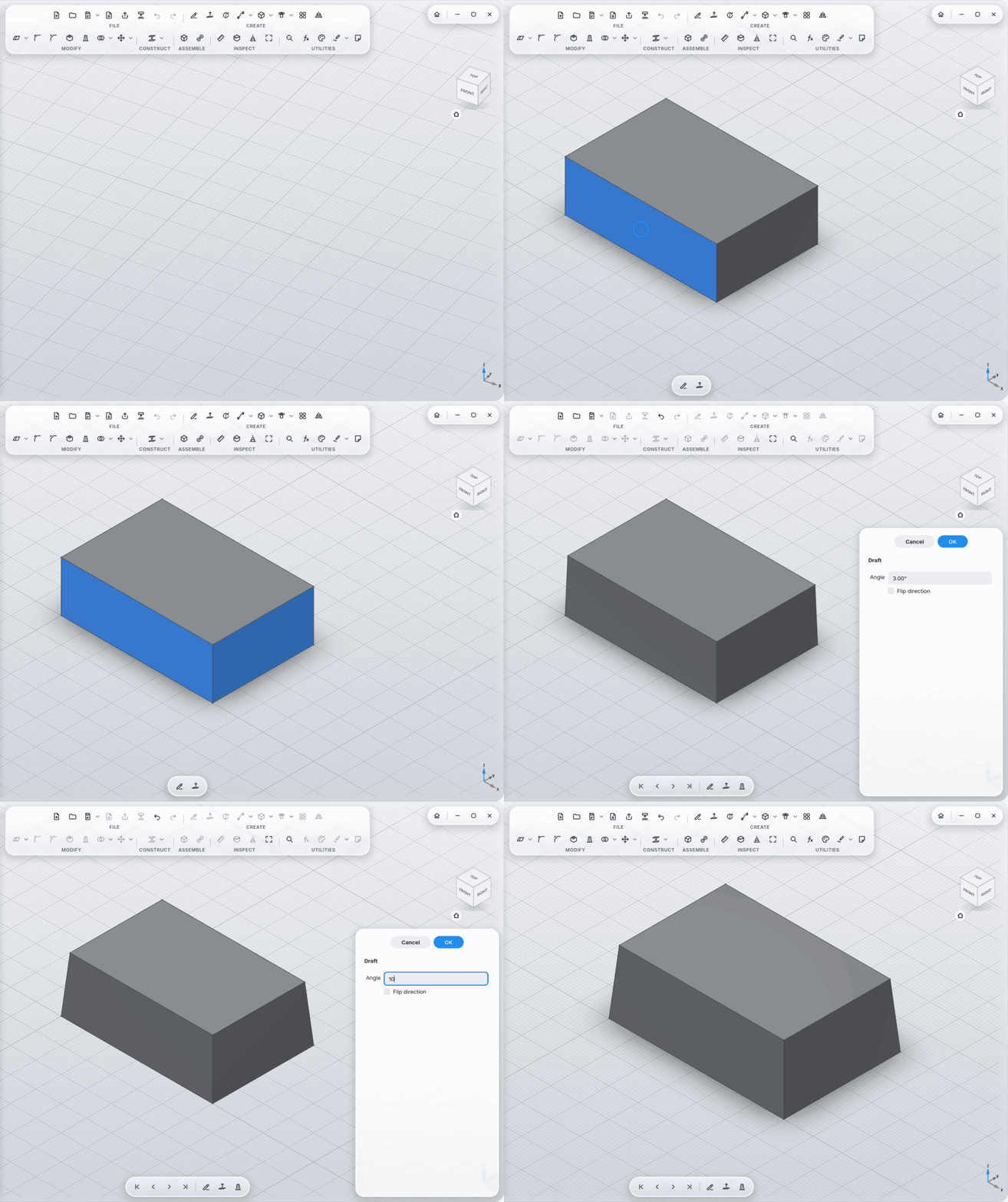
|
Combine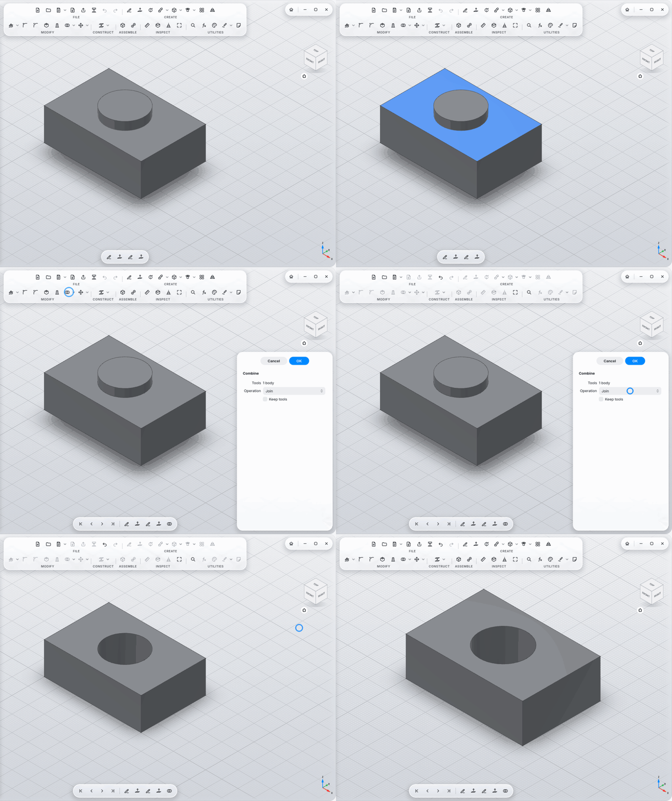
|
Split Body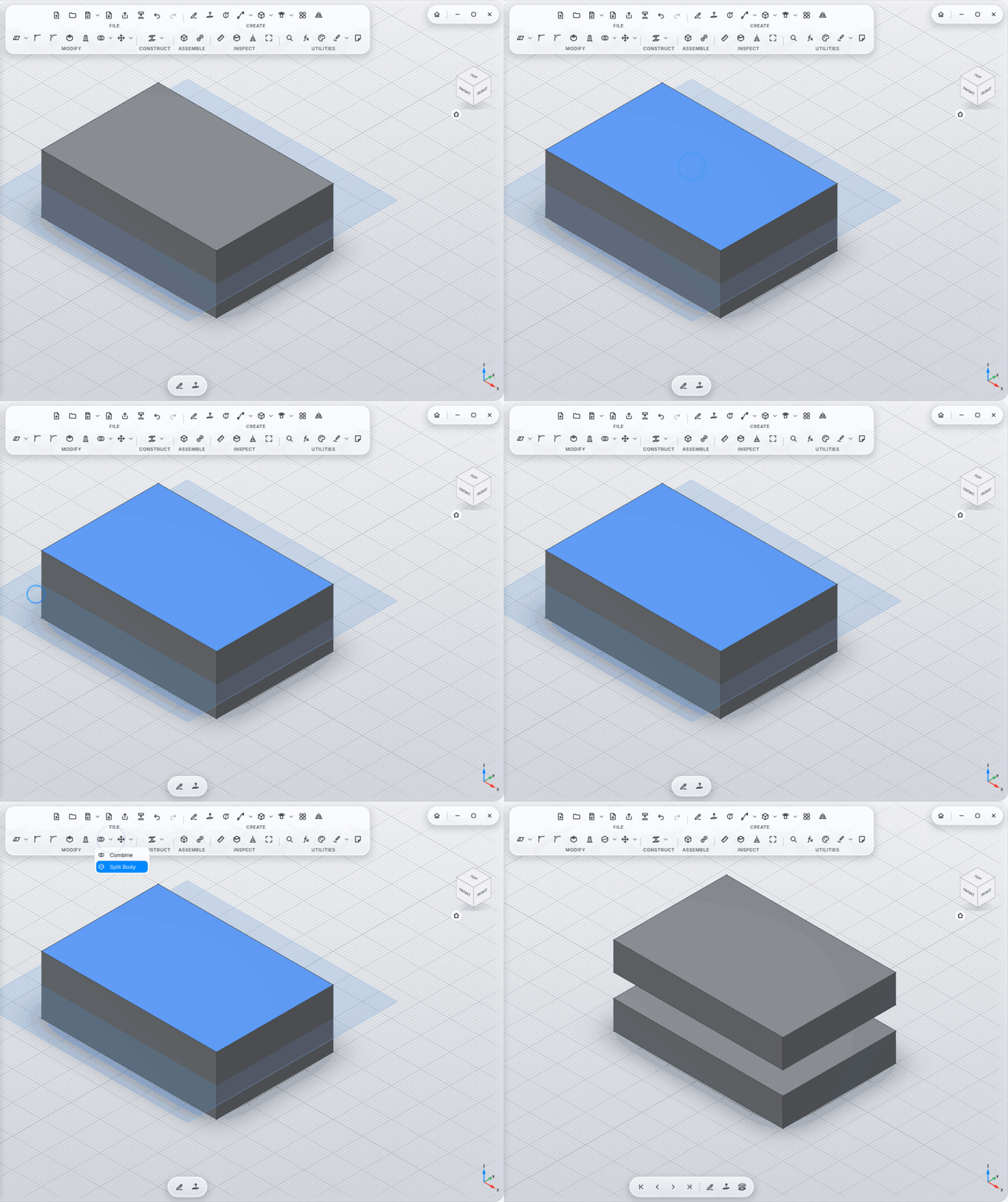
|
Align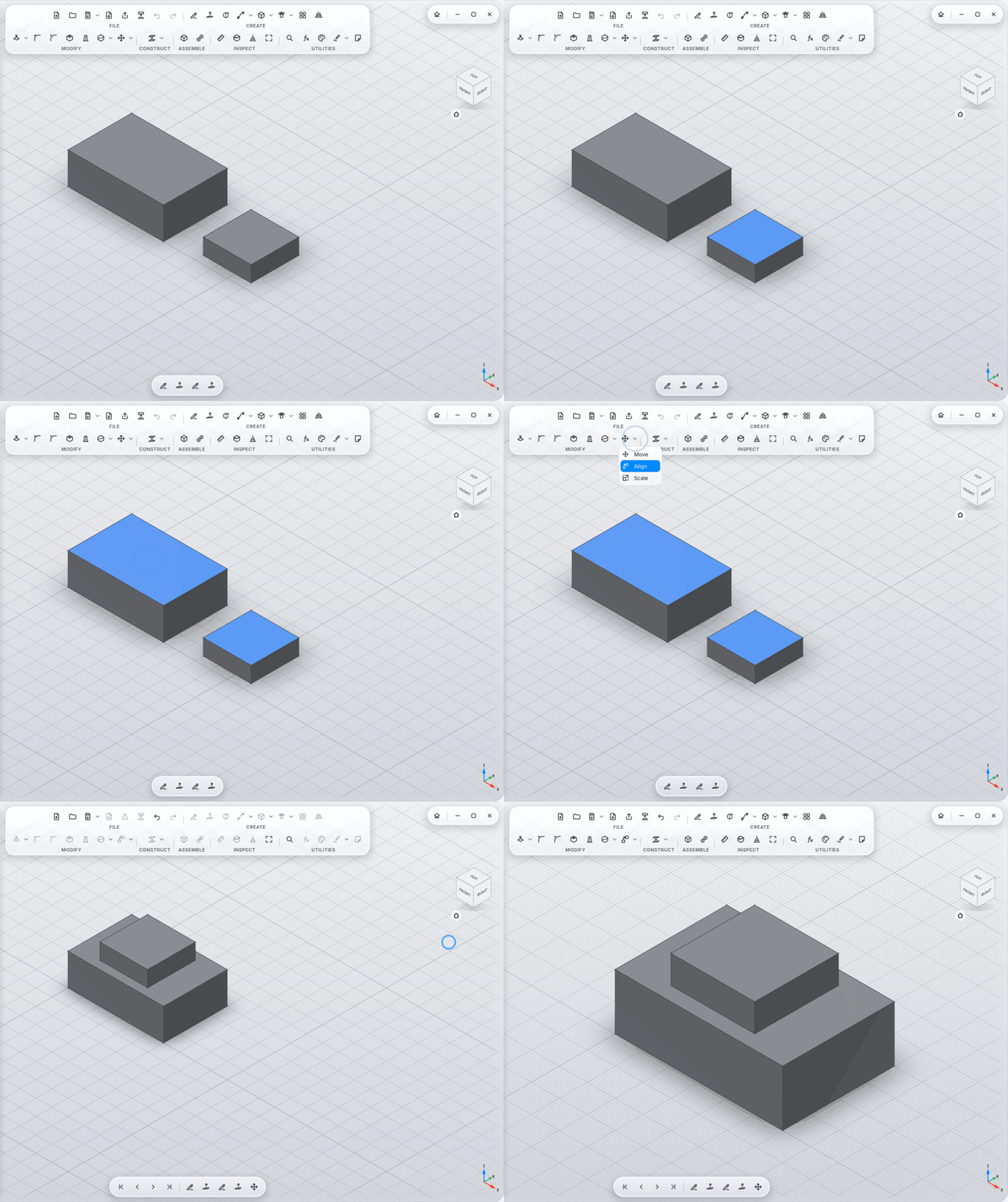
|
Scale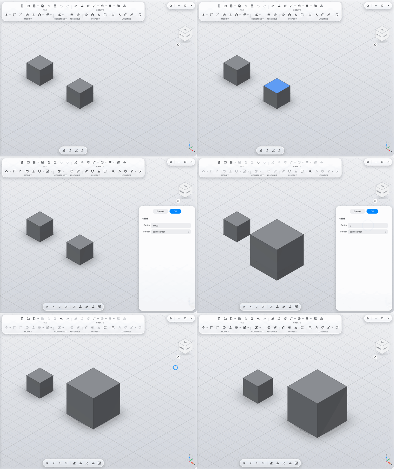
|
Delete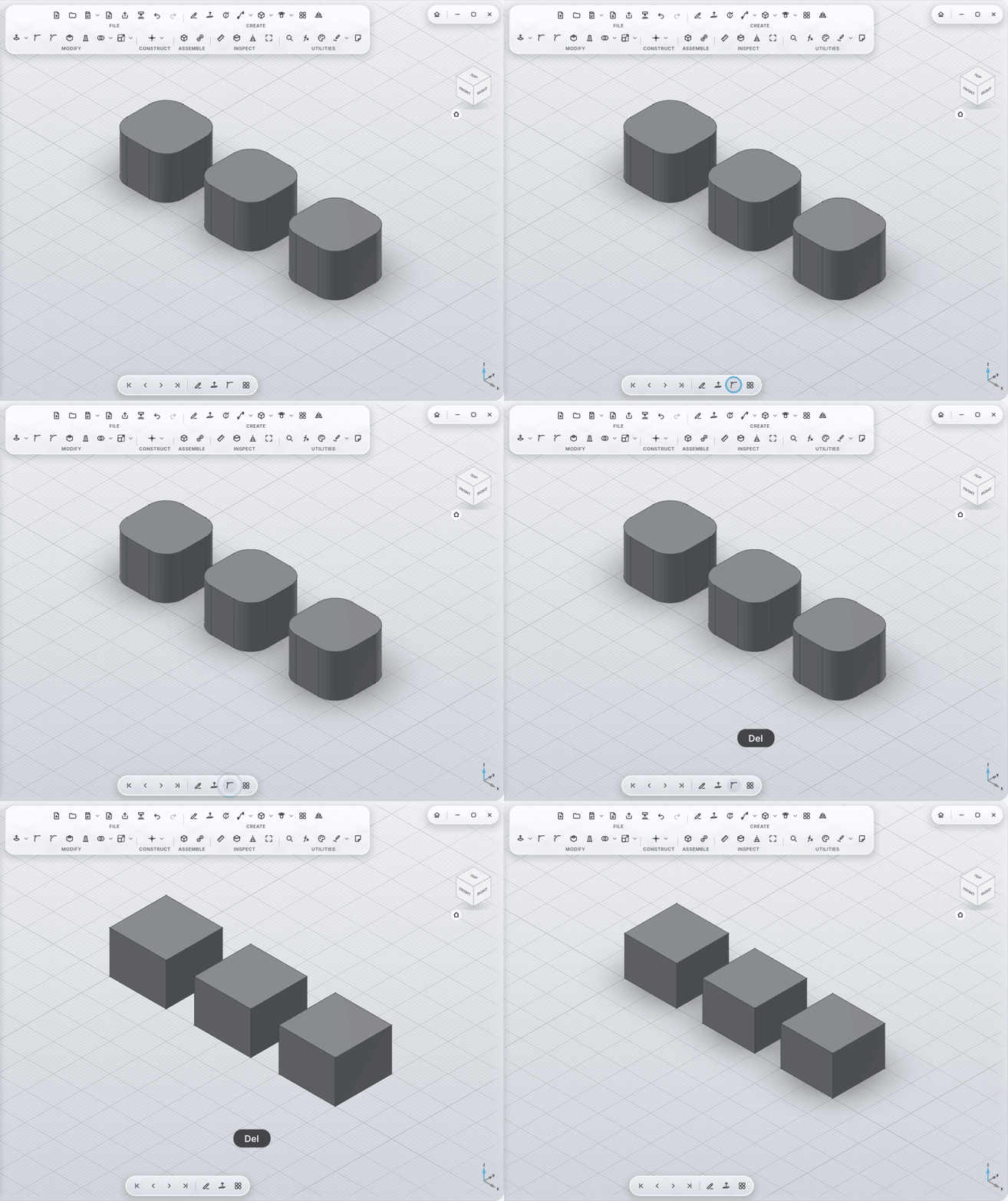
|
CONSTRUCT
Offset Plane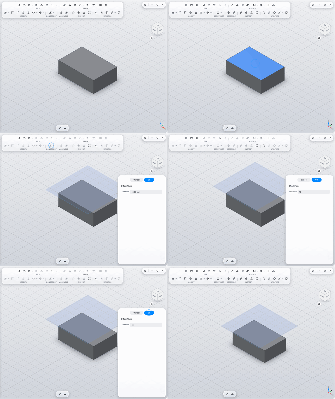
|
Plane at Angle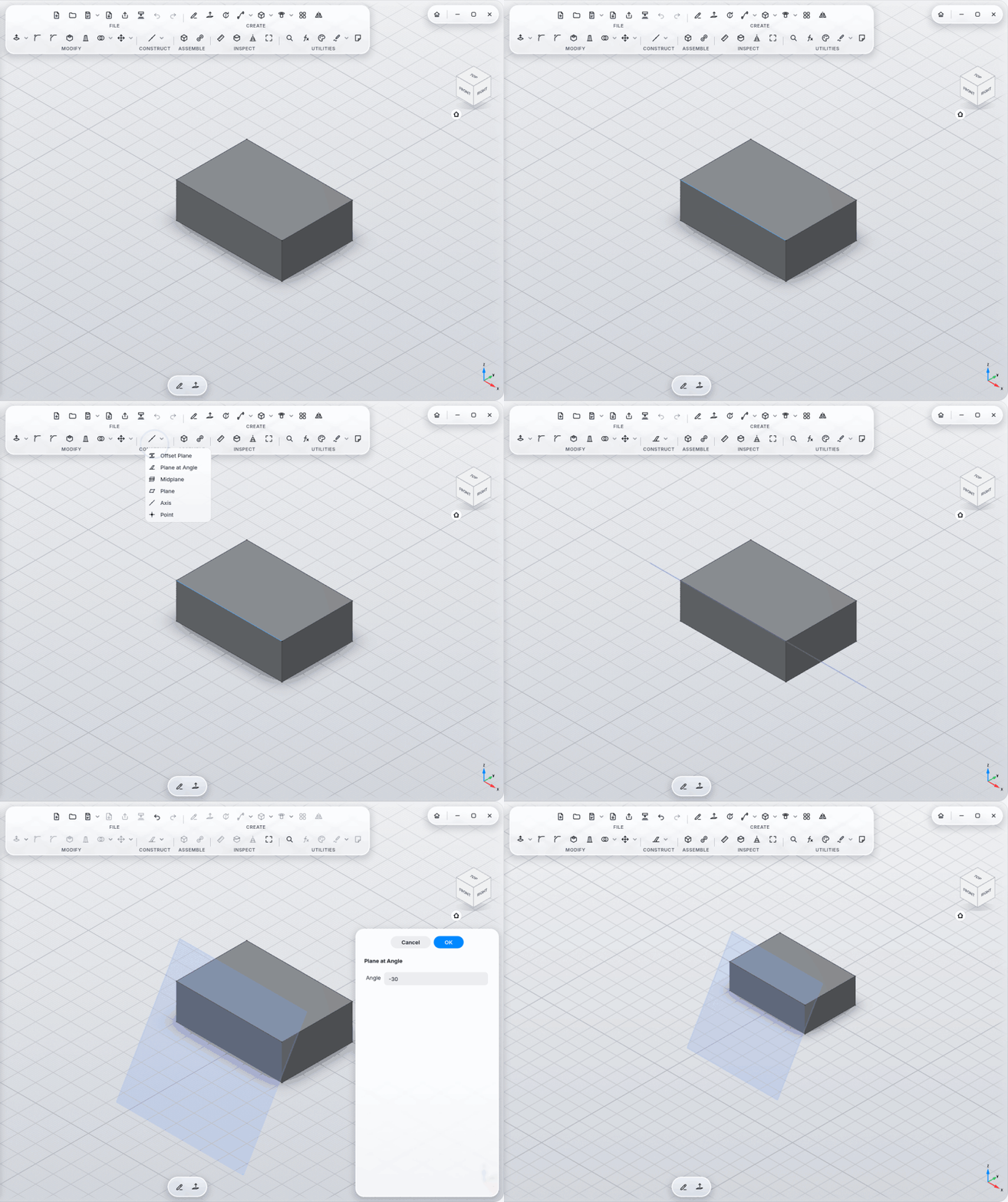
|
Midplane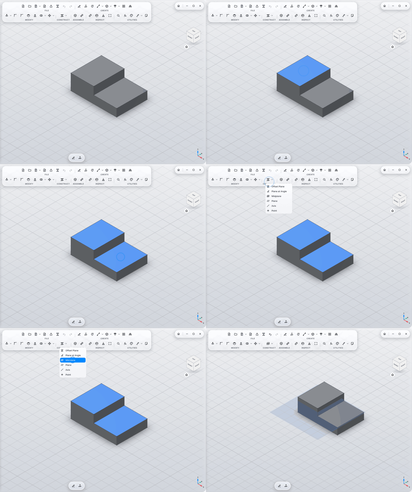
|
Plane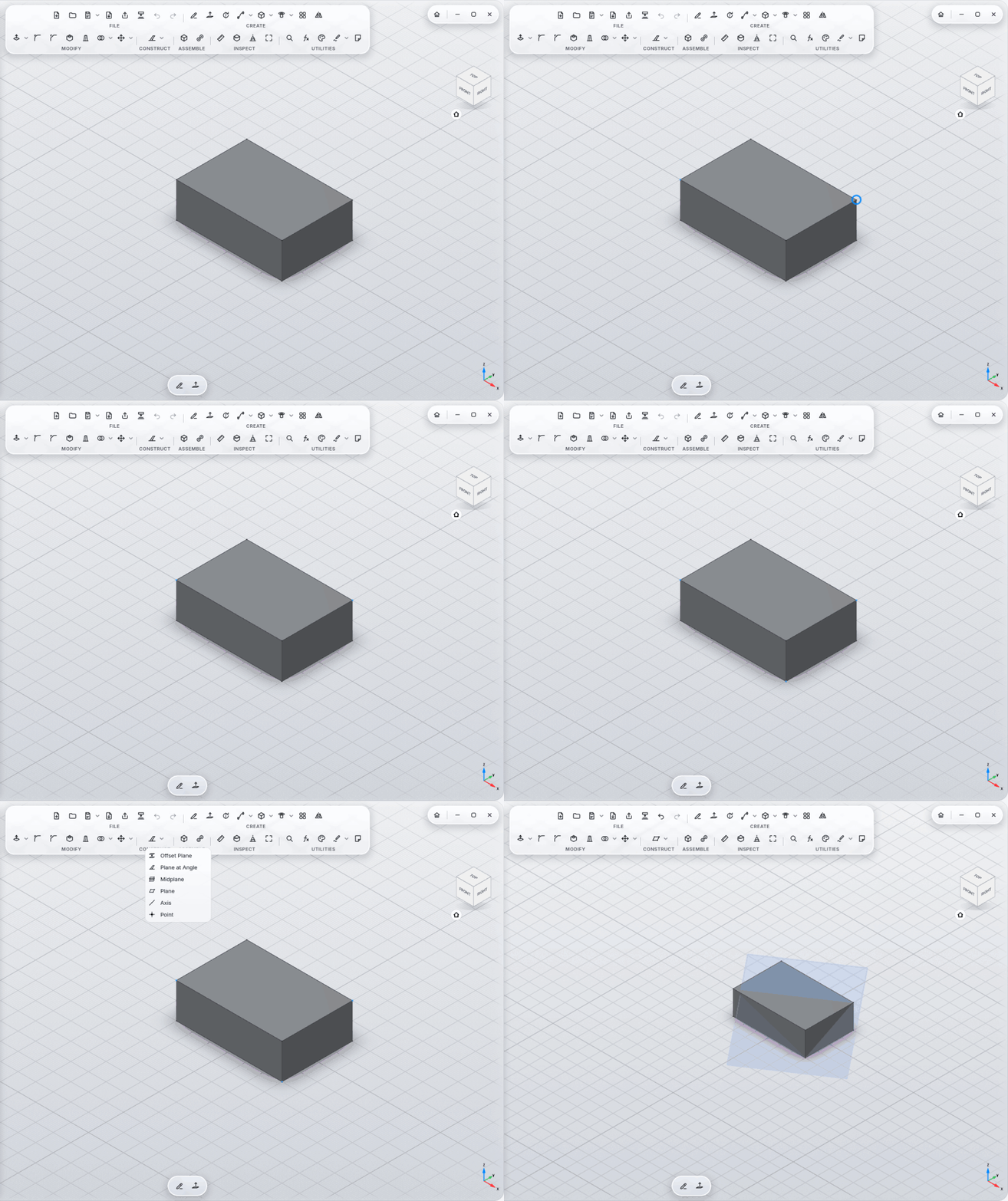
|
Axis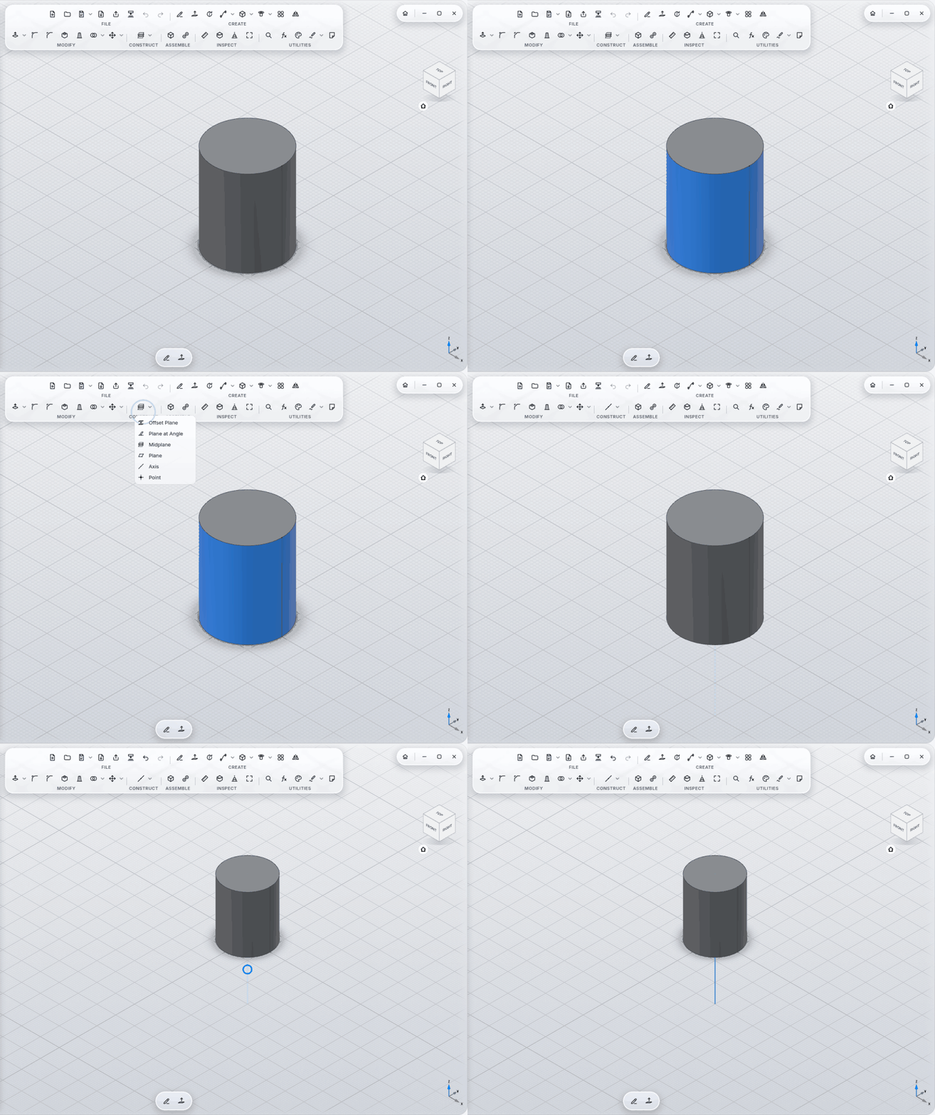
|
Point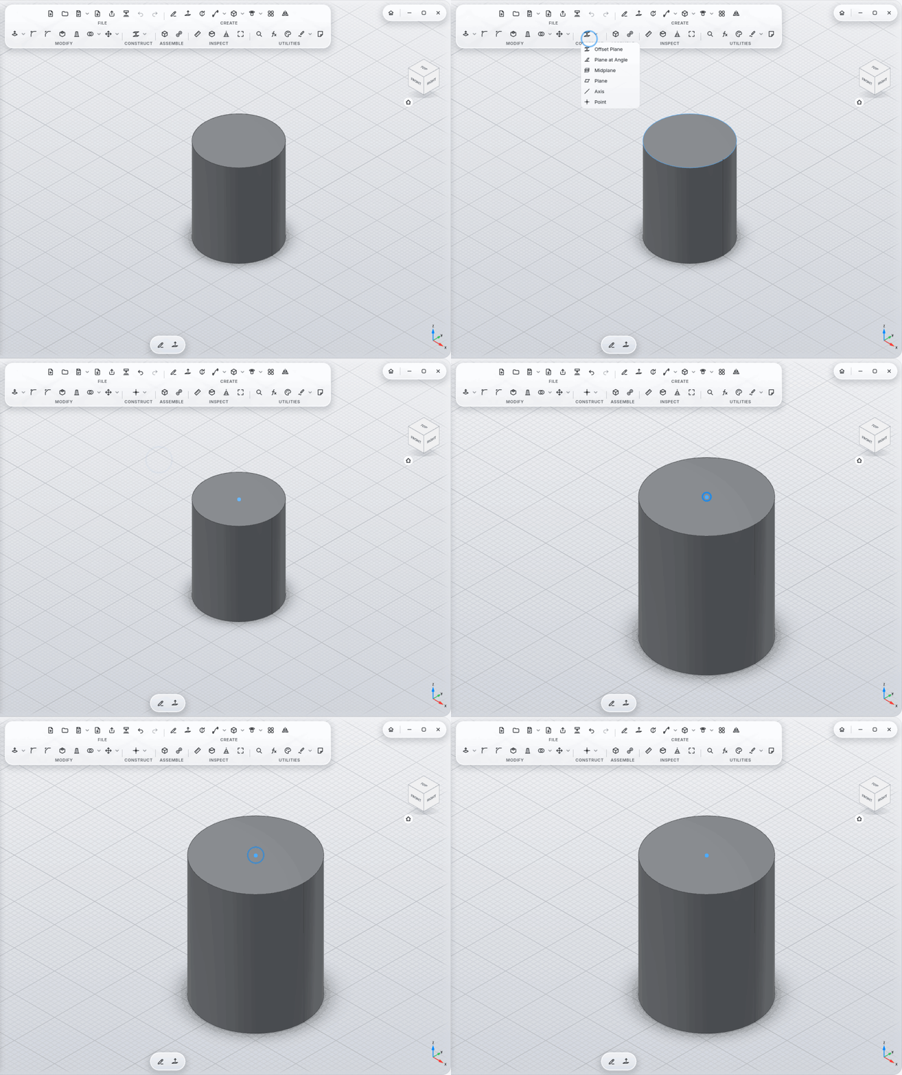
|
INSPECT
Section Analysis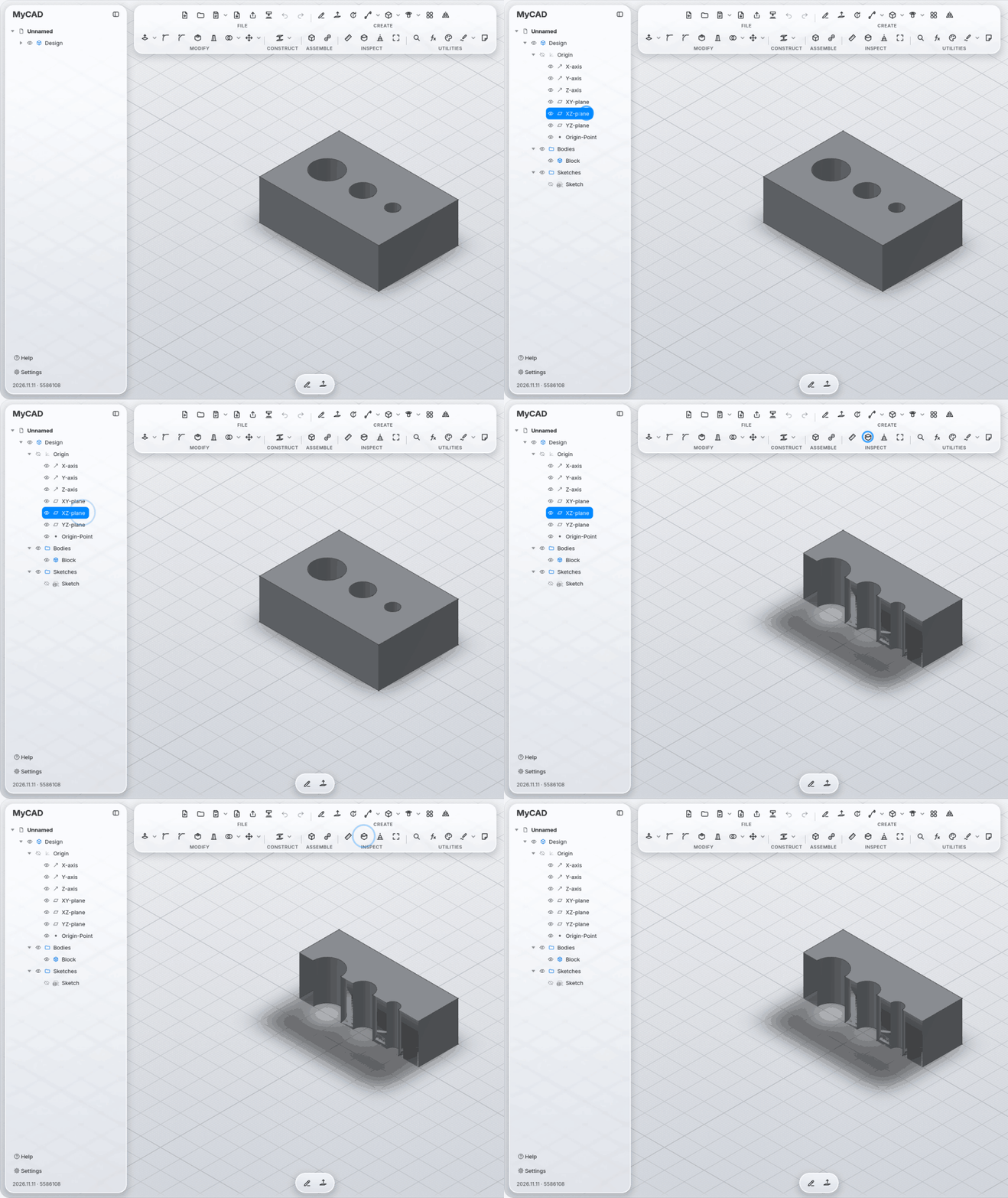
|
Fit All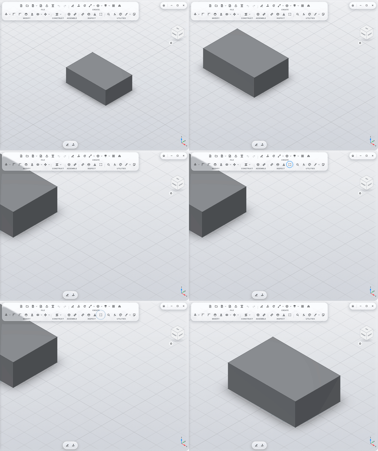
|
Lay a flat part on plain light paper, photograph it from straight above, then FILE → Import and choose the photo (PNG or JPG; also Ctrl+K → Photo to Sketch). Easiest: the part on a whole white A4 sheet on a darker table, all four corners in the photo, angle doesn't matter: MyCAD straightens the perspective and asks nothing. On grid paper it finds the squares and only asks their size (usually 5 mm); on plain paper type how wide the part really is: MyCAD traces the outline and every hole as a sketch to scale, ready to extrude. Round holes become real circles, everything else straight lines.
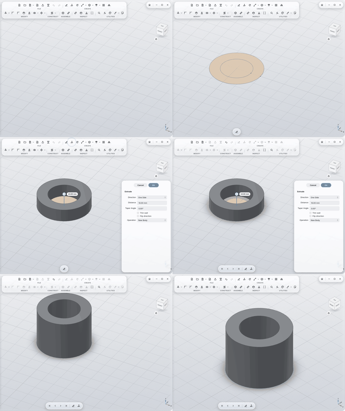
Direction One Side, Symmetric, Two Sides, To Object (up to a face or plane) or All (through everything). Plus a Taper angle (positive narrows) and thin wall (just a rim of a given thickness). Operation: new body, join, cut, intersect. Clicking a flat face of a body and extruding it works like Press Pull. A cut goes through everything in its way, also bodies of other components (a hole through a part and the plate it sits on); a new part in its own component that only overlaps other components stays a body of its own.
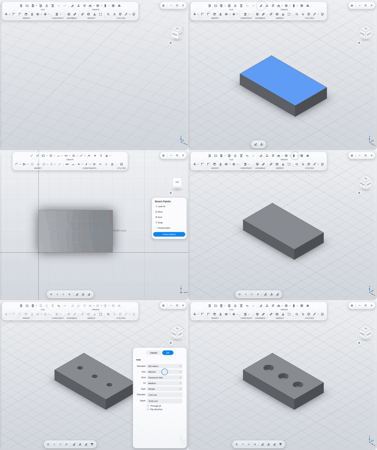
Click Hole, then the face where it goes. Near the middle of the face (or the centre of a round face) the hole snaps there, elsewhere to the nearest 0.5 mm, and it gets dimensions to the two nearest edges by itself: to move it later, change them in its sketch. While the panel is open, click more spots for more holes: one at the same distance from an edge as an earlier one snaps to it and is bound to it, so the row moves together. For several holes at exact spots, place points in a sketch on the face, select it, then Hole. With a Standard (ISO metric, ISO metric fine, UNC, UNF) MyCAD fills in everything: a clearance hole with fine/medium/coarse fit, or a tapped hole (core hole, optionally with a real thread), and the counterbore or countersink of the screw. With Custom every value is free.
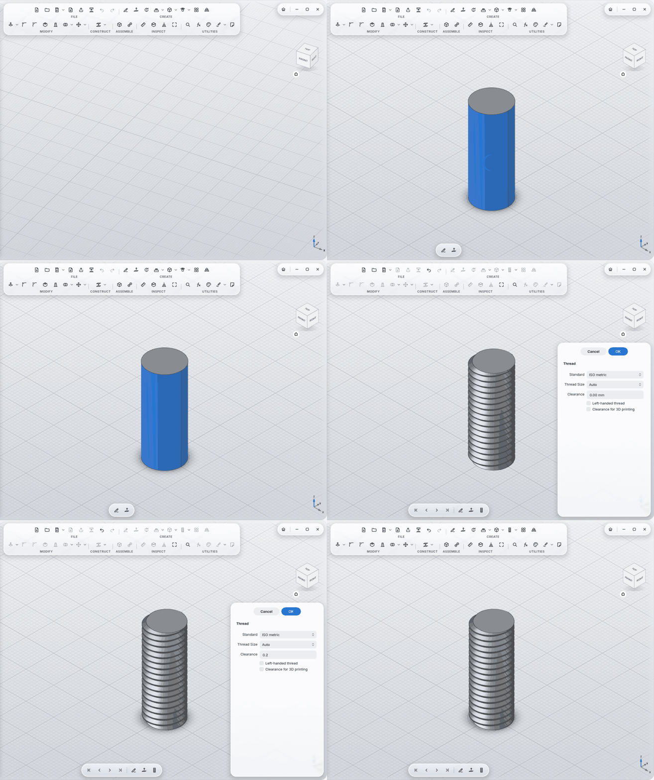
Click the cylindrical face of a bolt or a hole, Thread. The ISO size follows the diameter. Clearance per side for printed threads, or tick "Clearance for 3D printing" and let MyCAD pick it.
- Fillet with a constant or variable radius (start/end).
- Chamfer with equal distance, two distances or distance and angle; side can be flipped.
- Shell hollows a body out; choose the open faces.
Fillet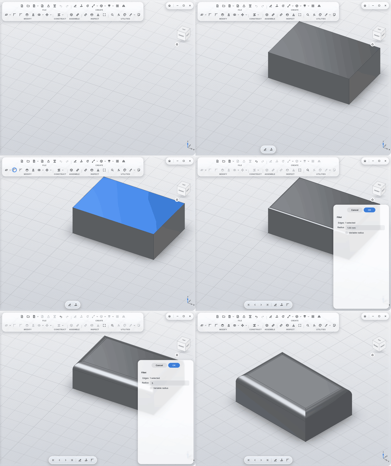
|
Chamfer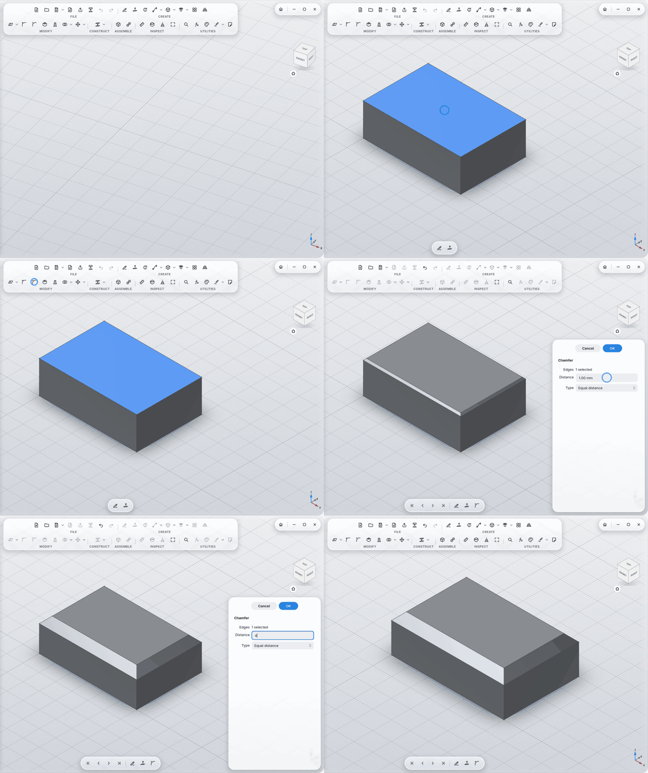
|
Shell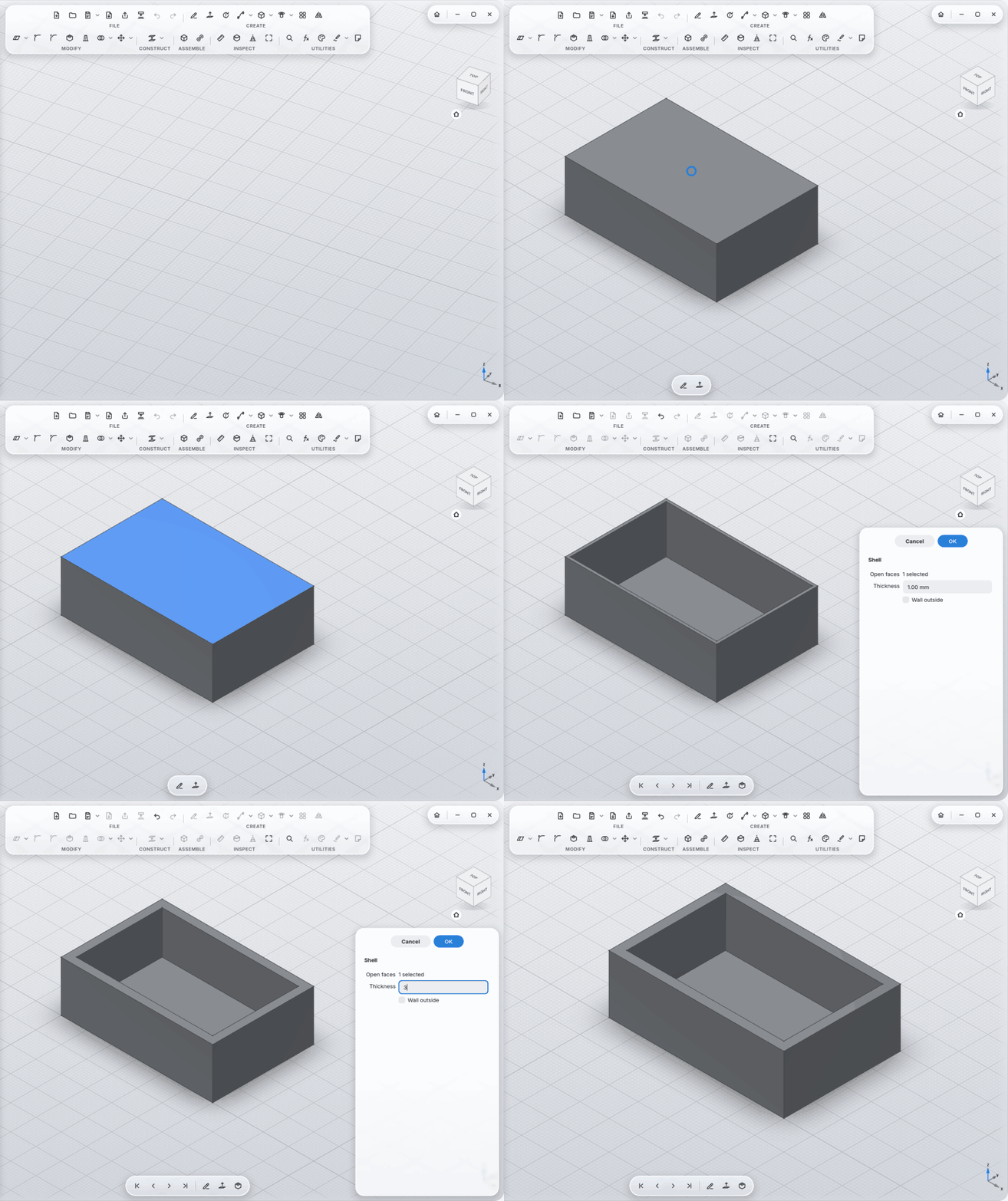
|
- Pattern rectangular, circular or along a path (edges); directions and axis from edges, axes or face normals; copies can turn along the path. Works for features (extrusion, hole) and whole bodies.
- Mirror across any plane or flat face.
- Move by distances and rotations, also around a chosen axis.
Pattern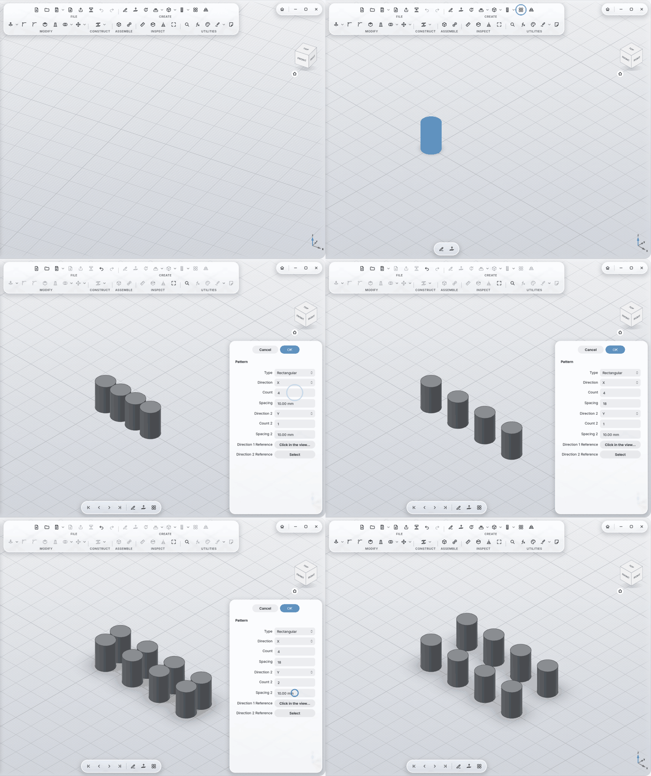
|
Mirror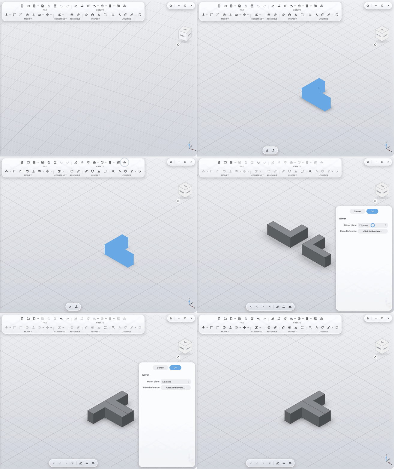
|
Move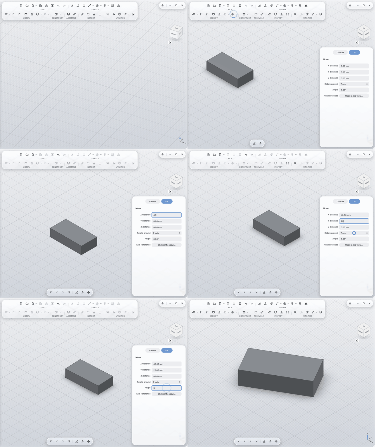
|
Select faces, Remove Face: the faces around them grow over the gap. Fillets, chamfers, holes or pockets disappear again, which is handy for imported STEP parts that have no history.
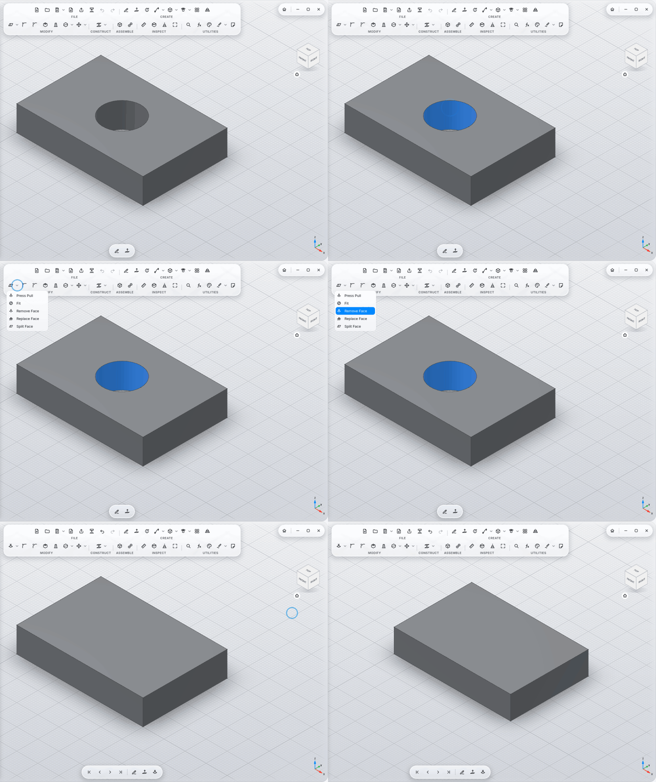
-
At the bottom center, one entry per step; double-click to open it again.
-
What depends on it: hold the mouse over a step and the steps that depend on it light up; the tooltip names them.
-
Delete with a preview: if something else depends on what you delete, MyCAD asks first and lists it: bodies that go along, sketches that lose their face (they stay in place, with a warning), steps that lose their input. For a whole body its own steps go along quietly; named are its mirror/pattern copies, a Combine that used it as the only tool, and other bodies' sketches or steps built on its faces.
-
Check References (Ctrl+K, or right-click a step with a warning) lists in one place every step that no longer finds its edges or faces for certain: lost profiles and faces, edges found again by their position, references to elements that are gone. Each row has Show, Edit (choose again) and, for a guess, Looks Right.
-
Roll back: the arrows, or a click, move the marker back; later steps rest until you move forward again.
-
Reorder: drag an entry. If it needs another step, MyCAD says which.
-
Groups: Ctrl+click several entries, right-click → Group Selected Steps. Groups fold into a chip, and can be renamed and ungrouped.
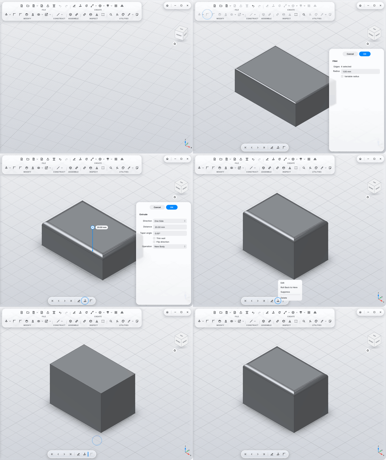
When a step fails, it gets a badge in the timeline and a plain-language message in the panel. Where possible, MyCAD works out a suggestion and shows it as a button:
- fillet or chamfer too big → the largest size that still works
- shell too thick, thread too short, revolve axis through the profile, screw too short
- the affected edges are marked on the model
If the model changes so that a selected edge may no longer be the same one, MyCAD takes the closest match and marks the step orange: Show Affected Edges or Looks Right.
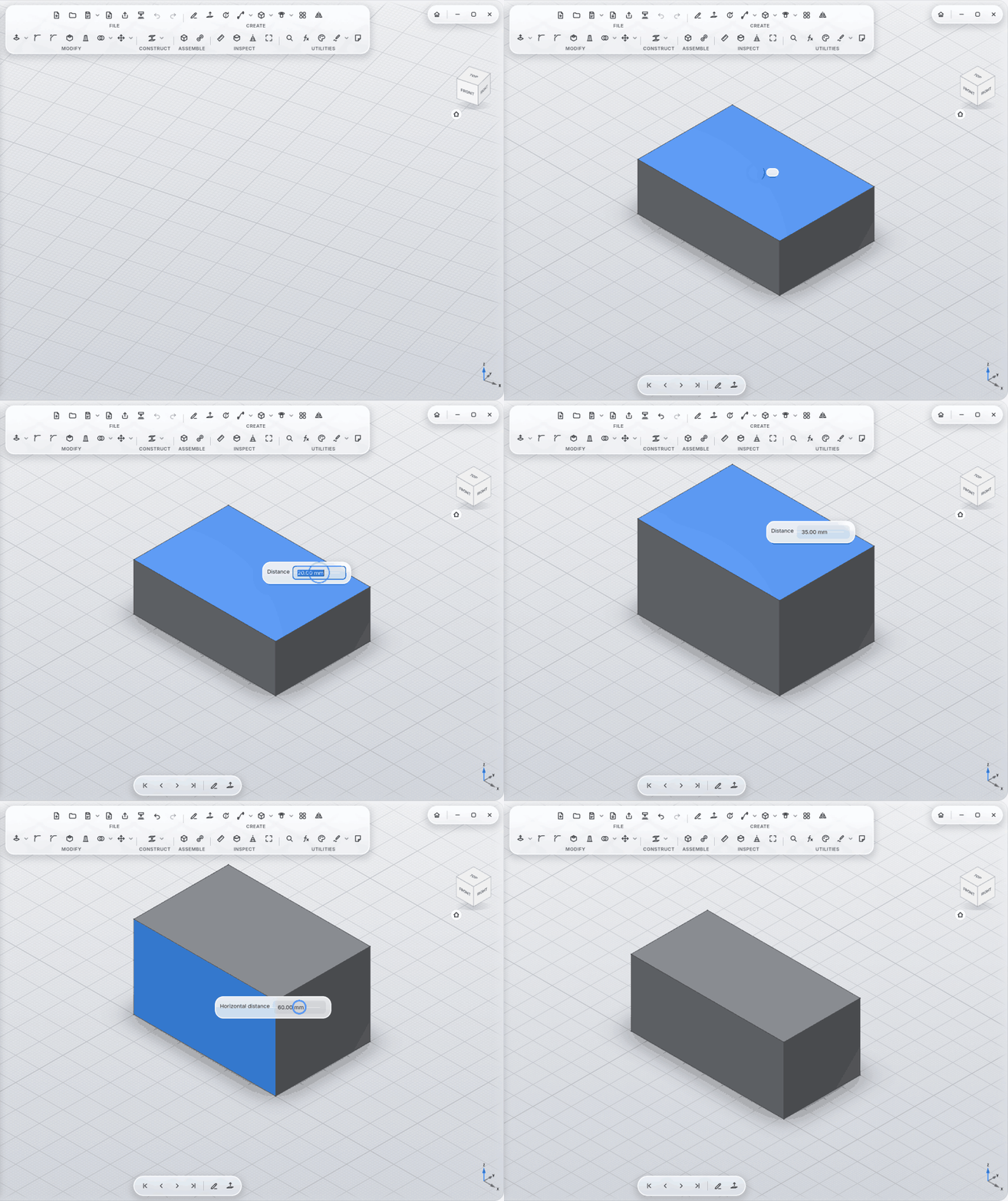
With no tool active, double-click a face (a single click only selects it): a glass card next to it shows the sizes that make it: the extrusion length of a top face, the sketch dimension of a side face, a hole diameter, a fillet radius. Type a number or formula, press Enter. If the size is a parameter, the parameter changes (and so does the note it's written in). A formula can't be overwritten here; change the parameter instead.
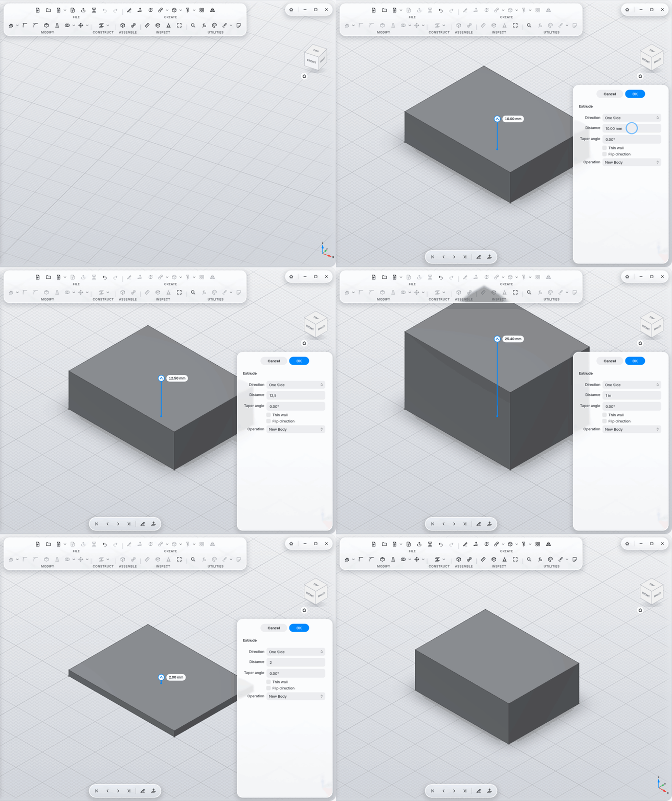
Every size field takes a number (12,5 and 12.5 are the same, millimetres unless you say otherwise), a unit
(1 in, 3 cm), a calculation (2 * 7,5) or a parameter name (Width / 2, then Enter: the field stays linked).
The model follows while you type; Enter after a plain number is the same as OK. Inside brackets a comma separates
values, so write 2 * (1.5 + 1) with a point there.
Ctrl+K opens the search at the top center. It finds commands, bodies and sketches, forgives typos, understands English and German, and words from other programs (pocket, pad, thread, fit, slicer). Enter runs the first hit; the ones you used last are at the top.