Workflow
Building upon the described interfaces and formats, the specific workflows for the utilization of the MOSIM MMI framework are presented in the following.
The launcher can be considered as the entry point of the overall MMI framework. The launcher provides a central service, named MMIRegisterService (see 3.2), which offers accessing functionalities of all registered adapters/services and available MMUs. Figure 92 gives an overview of the sequence-diagram of the launcher.
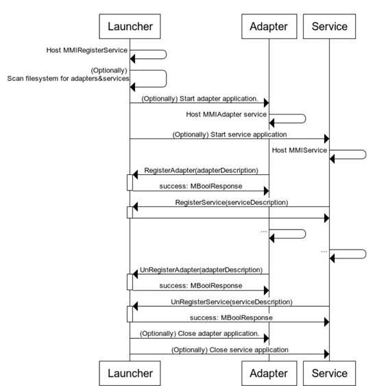
The launcher initially starts hosting the MMIRegisterService (see 3.2.9) which serves as a central registry for the overall system. Next, the launcher optionally scans the file system for executable adapters and service applications (using the MExecutableDescription). If desired, the launcher automatically starts and manages the respective processes. Each adapter and service registers itself at the central register using the specific MAdapterDescription or MServiceDescription. Therefore, it is also possible to add external adapters or services, which were not explicitly started and are not managed by the launcher. If an adapter or service is terminated, the unregister function of the MMIRegisterService is used together with the respective MAdapterDescription or MServiceDescription. From this point, the adapter and service are not further listed as available. Moreover, if the launcher internally started applications such as adapters or services, the applications are automatically closed once the launcher is shut down. The launcher component is provided in addition to this document as part of the MOSIM deliverable.
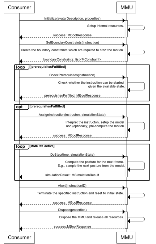
Despite the description of the workflow of the launcher, which serves as the entry point, it is also crucial to define the workflow of the specific MMUs. In general, the MMU execution can be subdivided into different phases, namely Initialization, Computation and Termination. The sequence diagram below (see Figure 93) illustrates the overall workflow of executing an MMU from an MMU perspective.
First, the MMU is initialized given the MAvatarDescription of the intermediate skeleton as well as additional properties. The MMU indicates whether the initialization was successful by returning a MBoolResponse. After initialization, the superior instance or consumer might call the GetBoundaryConstraints method of the MMU. Therewith, the MMU needs to return boundary constraints, which are relevant to start/end the motion. In particular, these constraints are important for the transition modeling (e.g., start posture). For a data-driven MMU that solely plays back a motion, the returned boundary constraint could be the first posture of the played back motion.
Next, the CheckPrerequisites function is called by the consumer/co-simulator. The MMU is responsible for indicating whether the intended instruction can be executed given the present state of the scene.
Within the computation phase, the AssignInstruction method depicts a major functionality. In order to compute and express the desired motion, the AssignInstruction method is executed given a specified MInstruction and the present MSimulationState. The method is only executed if the CheckPrerequisites function of the MMU returns true. This method might require more time than actually available for real-time computation. For instance, the internal model could be set up, paths or entire motions could be pre-computed. The MMU returns a status whether the assignment was successful (MBoolResponse). Being executed for every frame, the DoStep method is responsible for the actual computation/generation of the individual frames and postures. Therewith, the function gets the delta time (time to be simulated), as well as the present simulation state (MSimulationState) as input. The method returns the generated MSimulationResult. The DoStep method is executed until the MMU generates an End Event expressed using the MSimulationResult or the consumer aborts the instruction using the Abort method. Within the Abort method, the MMU is responsible to terminate the specified instruction and reset the internal state to the initial state. Furthermore, if the simulation environment/MMU is completely terminated, the Dispose method is used.
The adapter forms an essential aspect of the framework, encapsulating the MMUs in the respective programming language while buffering the scene. Similar to the MMUs, the adapter workflow is subdivided into different phases that are described in the following.
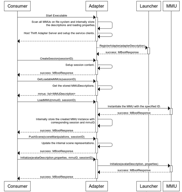
Initialization Phase In general, the external consumer or launcher starts the adapter application at the beginning. In particular, during startup several arguments must be passed to the adapter. The address of the desired MMIAdapter server (-a), the address of the MMIRegisterService (-r) and the file path or url of the MMU directory (-m) must be provided as console arguments. An exemplary set of startup arguments is illustrated below:
-a 127.0.01:8000 –r 127.0.0.1:9009 –m C:\MMUs\
After the adapter application has been started, the adapter hosts the respective MMIAdapter thrift server to be accessible from external consumers, whereas the specified address parameter (-a) is used as hosting address. Note that the implementation for the MMIAdapter must be specifically provided for each programming language. Furthermore, the adapter scans the file system or remote location, as specified using the –m parameter, for compatible MMUs. In particular, the MMUDescription files are utilized for analyzing the compatibility. If the MMUDescription contains the same programming language and supported dependencies as the adapter, the MMU is considered as compatible. The list of compatible MMUs and resources is internally stored within the adapter. In order to be visible within the MOSIM framework, next, the adapter registers itself at the MMIRegisterService using the register address provided as argument.
After the adapter has been successfully registered at the launcher, the adapter is now visible for all clients. From here on the client can create a session at the adapter using a specified session ID. It is noteworthy, that the adapter manages an individual set of MMUs, avatars and scenes for each sessionID. Given the created session, the client can now request the loadable MMUs and select the desired MMUs to be loaded. The adapter internally instantiates the respective MMUs and returns a status flag indicating whether the operation was successful. The instantiating process strongly deviates between the heterogeneous programming languages. For a C# adapter, the instantiation is realized using the Reflection functionalities of the .Net framework and .dll files, whereas for Java .jar files are utilized. Therefore, the instantiation needs to be manually implemented for each programming language.
After the MMUs have been instantiated, the client can initialize the given MMU with the respective mmuID and sessionID. The mmuID is provided within the MMUDescription file, read by the adapter. In before, the client pushes the full scene to the adapter using the PushScene method.
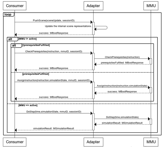
Computation Phase: After the initialization of the adapter and the respective MMUs, next the actual motion can be computed within the computation phase. Figure 95 visualizes the corresponding sequence diagram. During the computation phase, the consumer pushes the scene changes to the adapter at the beginning of each frame, ultimately resulting in a synchronized scene on a per frame basis. For this purpose, the PushScene method of the adapter is utilized, transmitting the delta scene changes using the MSceneUpdate class. Next, similar to the MMU workflow, the prerequisites of the instruction are checked. If the prerequisites are fulfilled the instruction is assigned. Different to the direct accessing of the MMUs, at each call, the sessionID and mmuID must be additionally specified to allow the adapter identifying the respective MMUs. For the actual frame wise computation of the motions, the DoStep method of the adapter with the specified mmuID and sessionID. Internally, again, the respective MMU is called and the result returned to the consumer. The adapter therefore acts as proxy between the consumer and MMU.
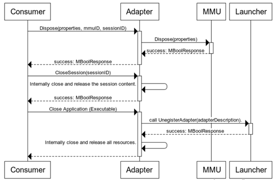
Termination Phase: To terminate specific MMUs, the Dispose function specifying the mmuID and session ID is used. Moreover, after all MMUs have been disposed, the session can be closed using the CloseSession method. Internally, the adapter releases the allocated resources for the specified session. Finally, the consumer must terminate the adapter application (process). If the adapter process is closed, the adapter unregisters at the central Launcher using the Unregister method. In this way, the adapter is not any more visible to further consumers in the MOSIM framework environment.
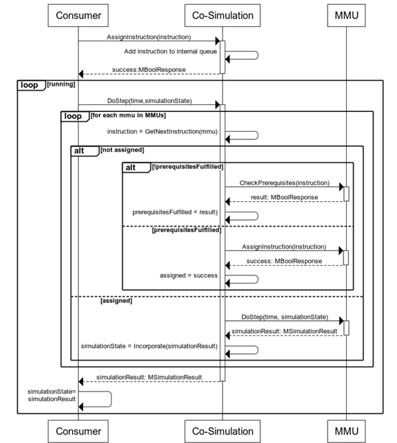
The co-simulation is generally responsible for executing the MMUs and generating an approved motion based on the underlying simulation approaches. As input, a sequence of instructions, as generated by the behavior execution is provided. The output is a feasible human posture for each frame. In the following, the execution sequence for the co-simulation is illustrated. The network communication in between is not further considered. Figure 97 visualizes the sequence diagram of the proposed co-simulation.
Initially, the consumer assigns instruction(s) to the co-simulation calling the AssignInstruction method. Since the MInstruction class can contain a further list of multiple instructions, it is also possible to provide several instructions as input. Internally, the co-simulation stores the instructions in a queue and returns a response whether the assignment was successful (MBoolResponse). Similar, to the MMUs, the co-simulation is also triggered by the DoStep function, which is cyclically called by the consumer. Within the DoStep routine, the co-simulation iterates over all MMUs according to its priorities and determines the next instruction to be executed. If the prerequisites of the instruction are fulfilled, the instruction is assigned to respective MMUs. Once the instruction is assigned, the MMU is called until it raises a finished event, or is externally aborted. The co-simulation furthermore, incorporates the results of the different MMUs. The result of the DoStep method is the incorporated result, represented as MSimulationResult.
The Behavior Model & Execution Unit is an important mediator between the task description to be simulated and the final result, as it queries the state of the scene and decides based on this, which motions or MMUs are to be executed. Figure 98 visualizes the sequence diagram of the behavior execution workflow.
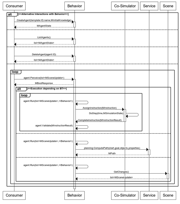
As described in the previous chapter, a simulated worker is represented in our approach by a software agent. For the administration of software agents, i.e. the creation, deletion or execution of such agents, four endpoints are offered:
- MBehaviorExecution:CreateAgent(MTemplate:ID,name,MInitialKnowledge): In order to create an agent, a reference to a predefined agent template is required, which contains, among other things, behavior models that the agent should use; a name; and the initial agent knowledge. This knowledge contains scene information and configuration data with which the agent can start with.
- MBehaviorExecution:ListAgents(): This function lists all agents.
- MBehaviorExecution:DeleteAgent(MAgent:ID): This function deletes the agent with the submitted ID.
- MAgent:Percieve(list): by sending scene updates to a particular agent, its reasoning cycle is activated because something in the scene has changed, and the agent may need to react. Internal BTs process this incoming information and decide how to deal with the new situation. These updates can be sent either event or game-tick based.
The reaction to new situations depends on the BT nodes used in a behavioral model. Either the updated agent knowledge is queried to check a particular situation and decide which behavior to execute later. Alternatively, new knowledge is generated based on the current situation or the current knowledge is updated. Besides these internal actions, the agent can also interact with other MOSIM components like the scene itself, the co-simulator or other services:
-
MBTScene:Run(): If the agent decides in a specific situation to read out certain information from the scene that was not previously transmitted via the MAgent:Perceive(list) method, it is queried via the MScene:GetChanges() function.
-
MBTService:Run(): Services should offer functions in MOSIM which can be used by different MMUs. They can also be used to support the decision-making process during Behavior Execution. For example, before generating instructions, the planned path planning service (ComputePath(start,goal,objects,properties)), could be used to determine whether a MoveTo-MMU can be executed with predefined parameters.
-
MBTAction:Run(): For the generation of instructions (MInstruction) a special branch node (MBTEvaluation) is executed to evaluate the underlying sub-behaviors and finds out which n-actions are to be executed next. Action nodes (MBTAction) represent motions or MMUs with predefined constraints that are considered during the evaluation with a simulated future agent state. After submitting the instructions to the co-simulator by the executed MBTAction, the Behavior Execution waits for responses from the co-simulator in which the status (MInstructionResult) of the motion generation is notified. If a new situation arises that requires a different instruction or if a MMU in the previously determined instruction could not be executed, the Behavior Execution must re-plan a new MInstruction.
-
MBTAction:Validate(MInstructionResult): The first action in a generated MInstruction validates the incoming MInstructionResult to its state and then changes its own state so that a new MInstruction can be generated.
The target engine is an essential component of the proposed framework. In particular, the target engine contains the ground through scene and triggers the overall simulation. In the figure below a proposed workflow for the target engine is provided.
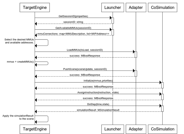
Initially, the target engine requests a unique session ID at the launcher/MMIRegisterService. Afterwards, the target engine can request the available MMUs with the associated connection properties from the MMIRegisterService. Next, the target engine internally selects the desired MMUs to be loaded. The target engine calls the LoadMMUs method of the respective adapter in order to load the desired MMUs. It is noteworthy, that a MMU might be available in multiple adapters. Therefore, it is up to the implementation of the target engine of which adapter to use.
After the MMUs have been successfully loaded, the target engine needs to provide the selected MMUs to the co-simulation. If the co-simulation is accessed using the proposed interface, a list of the unique id of the MMUs as well as its priorities need to be provided to the co-simulation. After the initialization of the co-simulation, the target engine can access its functionality. In particular, for each frame, the scene is pushed to each utilized adapter. The results of the co-simulation are applied to the scene at the end of each frame.
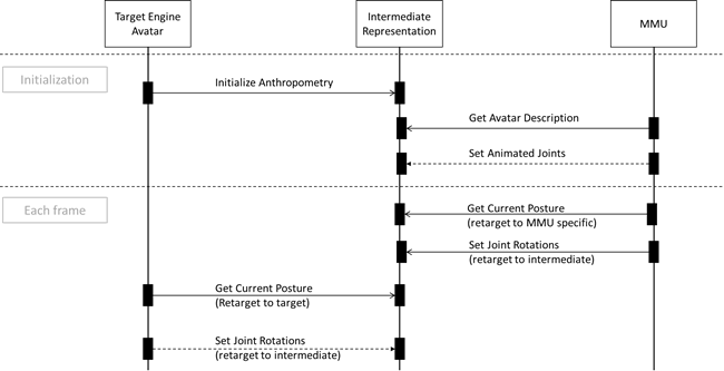
Despite the previously illustrated workflows, the interaction with the MSkeletonAccess depicts also a major aspect of the overall framework. Therefore, in the following an overview of the workflow of the skeleton utilization is provided.
Within the document, a first draft of the planned standard is proposed. In particular, the overall concept of the MOSIM framework was introduced. A detailed overview of the components and its interfaces was given. Moreover, the workflows of the components were described in detail. The document should serve as a base for utilizing and implementing the MOSIM framework.
Note that the document is considered as a living and dynamic document which is updated throughout the progress of the MOSIM project. In particular, the interfaces, formats and workflows, as described within this document are a first draft and are utilized at a starting point for the implementation phase of the project. However, feedback and gained knowledge during the implementation will be fed back to this document and the proposed framework will be adjusted. Especially with regard to the constraints, major adjustments are expected, since the corresponding task, which will focus on the design of constraints, has not started yet.
With the provided thrift files and the presented class diagrams in addition to the document, a first version of the MMI framework can be implemented.