Screens
English · Deutsch
What is on every screen, what the menu marks mean, and how each screen is operated.
The top band is shared by every screen. From the right: STOP, the run clock (while armed or after a run), ARMED or SAFE, a FAULT code when one is reported, the output mode (LINK or SIM), and LINK or NO LINK.
STOP works on every screen. It disarms and latches: the bench stays disarmed until it is armed again. Navigating away, an alert expiring or the link recovering does not clear a stop.
ARM is at the bottom of a bench screen; STOP is at the top of the band.

| Mark | Meaning |
|---|---|
| SOON | the screen does not exist; the tile lists what it will do and what it waits on |
| MODELLED | the screen exists and works, but its hardware is not fitted; every value is simulated and the screen says so |
| none | the hardware is fitted and the readings are measured |
The mark is derived from the capability bits the coprocessor reports at bring-up. A screen whose hardware is missing opens and runs from the model.
The menu in the light theme:


Each subsystem reports its result as it comes up: board, display, touch, SD card, settings, link, coprocessor. The board line carries the panel's own firmware version, and the coprocessor line carries the protocol version and the firmware version that the coprocessor reported -- two boards can speak the same protocol and be different builds, and this is where that shows.
A missing card or an unusable NVS (non-volatile storage) is a warning. A touch controller that does not answer, or a coprocessor with a different protocol major version, is a failure and the bench will not arm.
When every step has answered, the splash hands over to the menu after a hold of 1.6 s; a tap skips the hold.

Two columns. The plot and the throttle take the left, the four readouts and the controls take a rail on the right, so reading the numbers and working the throttle do not compete for the same part of the screen.

The trace is the record of a run. It advances only while the bench is armed:
arming clears it, disarming holds it as it stood. The panel tag reads
LIVE TELEMETRY while it advances, TELEMETRY HELD while it holds a run, and
TELEMETRY IDLE before the first arm, when the plot reads no run recorded.
The right-hand axis label reads NOW while it advances and END where a held
one stopped. The readouts, the TABLE pane, the totals and the temperature
strip are live at all times, armed or not.
The window is 534 columns at 20 samples per second, 26.7 s. A longer run holds its last 26.7 s; what came before is in the CSV file and not on the screen.
The trace ends at the disarm, not when the motor stops. Disarming commands zero throttle and the propeller coasts down after it. That coast-down is on the readouts and not on the plot, and not in the CSV file either, which closes on the same edge.
Arming clears the plot, and a latched stop is cleared by arming, so the trace of a run a STOP ended does not survive making the bench usable again. One arming writes one CSV file, and the log viewer plots it.
The strip above both columns carries the poll rate, the link's error count (cyclic redundancy check failures and resyncs added together) and three temperatures. ESC and MOT come from the bench page. MCU is the panel's own die, read from the ESP32-S3's sensor: it is the display board's temperature, not the coprocessor's.
The throttle moves by how far a finger travels, not to where it lands. A press
on the track commands nothing, so a touch at the far end asks for nothing; a
drag across the whole track asks for the whole span, and the pin follows it
unramped. -1 and +1 at the ends of the track step one percentage point.
ARM is a hold. The fill fades from green to the danger red across two seconds, and the bench arms when the fade completes; letting go before then arms nothing, and the release itself arms nothing either.
The finger has to stay on the button. One that leaves it abandons the hold, because the gesture is contact with the control and not with the panel. Coming back is not resuming: the contact is finished as far as ARM is concerned, so arming after that takes lifting the finger and pressing again. A bench that disarms under a finger still held on the button ends the gesture too — otherwise the contact made to stop it would arm it again two seconds later. Arming flashes the whole button twice: white, black, red, and again, one drawn frame each. An armed bench carries the danger red, and DISARM is a press rather than a hold: stopping never needs a hold. DISARM and STOP stop the output immediately, with no ramp. RESET PEAKS clears the peak markers and leaves the live readings.
The telemetry panel's header shows the rated kV, the revolutions per minute per volt the motor is actually turning, and EFF, the second divided by the first.
The arithmetic behind it is sound. Terminal voltage divides into the resistive drop and the back electromotive force (back-EMF), so rpm/V under load is the rated kV scaled by the fraction of the voltage that reaches the back-EMF, and that fraction is the fraction of the input power that becomes mechanical. In an ideal motor the ratio is the conversion efficiency exactly.
The number on the screen is not that, for three reasons, and it is labelled EFF rather than efficiency because of them:
- It accounts for copper loss (I squared R) only. Iron loss, friction and windage fall on the mechanical side of the split, so the figure is an upper bound on shaft efficiency rather than a value of it.
- The bench measures pack voltage, not the motor's terminals, so the ESC's conduction and switching losses are inside the figure. It describes the drivetrain, and comparing it against a motor datasheet compares two different things.
- It is only as good as the rated kV. An error there maps straight into the percentage, and a figure above 100 % means the rated value is wrong; the screen shows that rather than hiding it, capped at 199 %.
The rated kV comes from the connected ESC when it reports one. No ESC reports
it yet, so in practice it is the Rated kV setting, which defaults to zero: a
guessed kV produces a plausible-looking percentage that is wrong, so with no
value the field is drawn empty and no percentage is shown. The measured rpm/V
is shown either way, being a measurement rather than an inference.
While the values are simulated, SIMULATION is drawn across the screen. The panel simulates only while no coprocessor answers, so the watermark goes when one does. What replaces it is what that coprocessor can actually measure: rpm from bidirectional DShot today, and its own sensors when a measurement front end is fitted. A quantity nothing measures is drawn as an empty field rather than as a modelled number.

Drag anywhere on the sweep to command a position. The solid arm is the measured position; the faint arm is the commanded position. The gap between them is the servo's own lag. The rings around the tip pulse while the servo is being driven. Lifting the finger does not let go: the screen keeps saying the last position every SERVO_HOLD_MS, so a servo stays where it was put. RELEASE, the button, is what returns the surfaces to centre -- and even that leaves the pins bound and driving, at the middle of their travel. A disarm, or leaving the screen, which disarms, is what stops the edges.
The screen drives the channels the binding marks as surfaces, not a fixed pin and not a fixed protocol. PPM's eight channels are surfaces too, so a bound PPM output moves with this screen exactly as a bound SERVO PWM one does. With no surface channel bound at all it commands nothing and no pin moves.
SPEED is the rate the bench may move the output, in degrees a second of the horn's travel, not a speed for the drawing alone. At 100% the command goes straight through and the servo moves at its own rate; below that the bench ramps the command in front of it, so 30% takes three times as long to cross as 90%. It applies to a held output as soon as it is changed.
ARM before anything moves. While the bench is not armed the coprocessor writes a pulse of length zero to every PWM pin, so the horn on screen follows the finger and the servo does not. The button is a two-second hold, the same gesture and the same fade as the one on MOTOR & ESC, and a press on it while armed disarms. Leaving the screen disarms and lets go of the pin: a screen that is not visible must not be holding a servo somewhere, or leaving the bench armed behind it.

Sixteen channels, each with 1.5 s of history and a bar for its current value. CH17 and CH18 are the two digital channels. A glitch is a spike in one lane; a dropout is a notch across all sixteen at the same instant.
The state block shows one of SILENT, FAILSAFE, FRAME LOST and LIVE, with one line of explanation:

In FAILSAFE the receiver is sending well-formed values it has generated itself; every trace is drawn red. Treat FAILSAFE as a stop, not as sixteen valid channels. Receiver buses describes the states.
The sequence is: device class, protocol, connect.
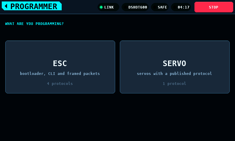
Every protocol row names its transport. There is no autodetection:
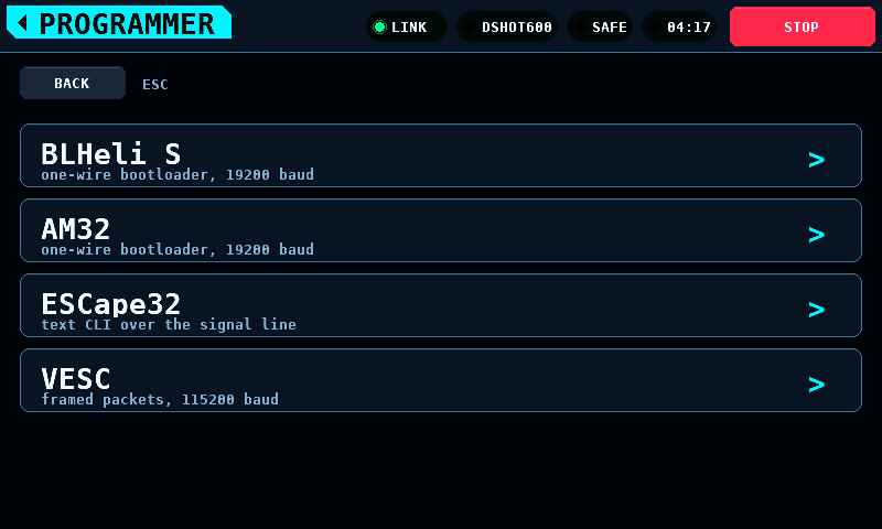
BLHeli_32 is not in the ESC list. The bench identifies and drives these ESCs and sends the DShot special commands, but cannot read their parameters: BLHeli_32 parameters.
Nothing is editable until a device has answered:

After a device answers, the parameters are shown in groups with the selected row's help under the list:
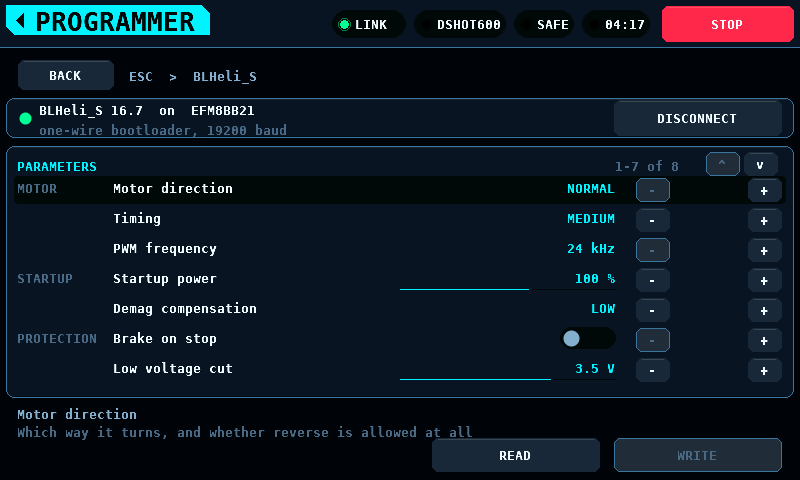
Each firmware shows its settings in its own units. BLHeli_S shows timing as named steps; the others show degrees of advance:

A changed value is not written until WRITE is pressed. Staged changes carry a mark and their own colour, and the WRITE button shows how many are staged:

Steppers stop at the ends of a list; they do not wrap.
Going back one level drops the connection. Back climbs one level at a time; the band's home tag leaves the screen.

Cells are drawn as their departure from the pack's mean. The verdict follows the spread, the widest gap between any two cells: HEALTHY below 30 mV, WATCH from 30 mV, REPLACE from 60 mV. The scale follows the pack down to a floor of 12 mV and is printed beside the plot.
Measure under load. At rest a weak cell reads like the others.

Browse the card, open a file, check what the import detected, then plot:

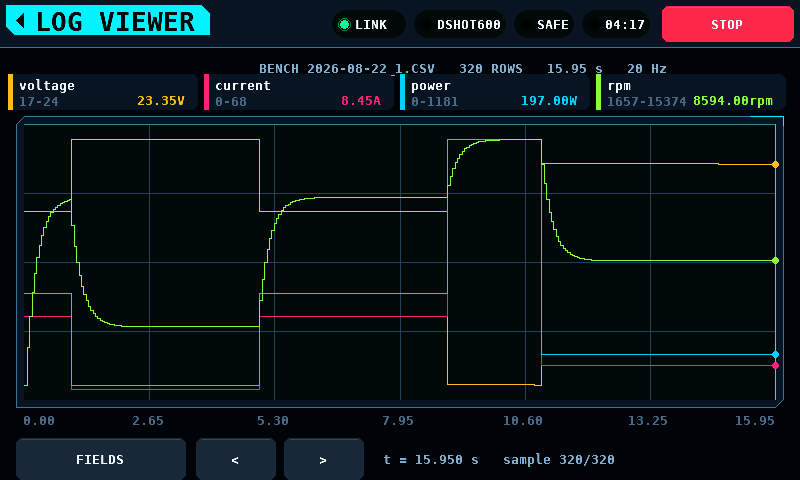
The CSV (comma-separated values) reader accepts decimal comma and decimal
point, a units row and ragged rows; the import view shows what it decided
before the file is plotted. Runs recorded by the bench are written as
BENCH001.CSV to BENCH999.CSV in the card's root directory.
The list holds 48 entries and a card holds up to 999 runs. When there are more
than fit, the list keeps the newest runs and its tab reads 48 OF 137 FILES
instead of FILES, so a run that is missing from the list is a run the list
was too short for rather than a run that was never written. The number in the
name is what newest means: the panel has no clock that survives a power cycle,
so every file on the card is dated 1980-01-01. A run outranks a file the bench
did not write, so a card holding 48 or more runs lists no other file. Delete
old runs on a computer to get one back.
A run is committed to the card every 20 rows or 1000 ms of run, whichever comes first. Power lost mid-run costs the rows the commit has not finished with and the rows still in the queue between the control task and the card's own task: under 1.0 s of run while the card keeps up, and 84 rows, 4.20 s at the panel's 20 Hz sample rate, if the card has stalled and the queue is full. The rest of the file is readable either way. The card is written by a task of its own: an SD (Secure Digital) card is allowed 250 ms to finish a write, and the task that beats the safety line has a ceiling of 150 ms.
Eight messages say what a card did to a run. Each appears on the band:
| Message | What happened |
|---|---|
no card -- this run is not recorded |
nothing is mounted, so the run was never opened |
card unreadable -- run not recorded |
the card would not list, so a run number could not be chosen |
card full or unwritable -- run not recorded |
no run number could be created |
the card did not keep up -- run not recorded |
every row was dropped, so there is no file for this run at all |
the card fell behind -- the log has gaps |
some rows were dropped; the file's time column shows where |
the card stopped taking rows -- run not recorded past here |
a write failed mid-run; every later row is rejected |
the card stopped taking rows -- the log is short |
the same failure, said again when the run closes |
the card failed on the last write -- the log is short |
the close failed, so the rows since the last commit are not in the file |
The first four mean there is no file to look for. The last four mean there is one and it stops early.
A run being written is not offered in LOGS. A file's length lives in its directory entry and is written when the file is closed, so a run still open would list at its last committed length and read as a finished one.
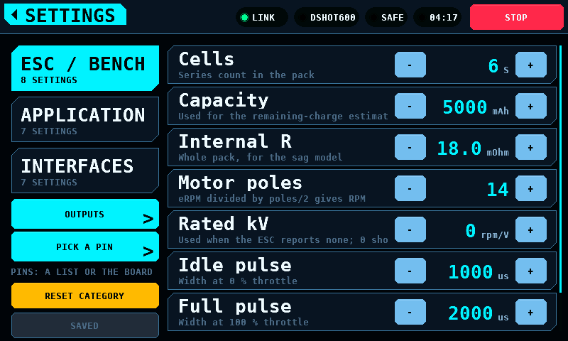
Settings are behind the SETUP tile, in both themes:

A changed value takes effect at once and is not written to flash until SAVE is pressed. The button under RESET CATEGORY says which of three states the screen is in:
| Label | Meaning |
|---|---|
SAVED |
Nothing is unwritten. The button is inert. |
SAVE |
Something is unwritten. Pressing it asks for a write. |
WHEN IDLE |
A write has been asked for and is waiting for a moment to happen in. |
NOT SAVED |
The store refused the write. What reached the medium is not known from the screen: a refusal on one key leaves the keys written before it committed, so the next boot can load a mix of the new values and the old. Pressing it tries again. |

The press asks; it does not write. Writing settings commits a page of NVS
(non-volatile storage), and a flash operation on the ESP32-S3 disables the
instruction cache, so neither core runs for its duration. The write is taken
on the first frame at which the bench is disarmed and no board photograph is
being fetched or stored. On the settings screen that is the next frame, and
the label goes to SAVED as fast as the eye follows the press. Armed, the
request stands as WHEN IDLE until the bench is disarmed.
A store that refuses leaves the label at NOT SAVED in the danger colour
until the next successful write or the next edit. A refusal does not undo what
was already written: the values are set key by key and a failure part way
through leaves the earlier keys committed, so the medium can hold a mix of the
new values and the old. The screen cannot say which. A panel whose NVS could
not be brought up at all refuses every write of the session, writes nothing,
and says so once more on the splash as NVS unavailable.
Values not saved are kept until the panel is switched off. Leaving the screen writes nothing.
The panel runs the CAN (Controller Area Network) echo self-test at every start-up, for 1200 ms inside the splash. A verdict other than every probe coming back intact puts this on the panel instead of the menu.

It exists because the fault is invisible from every other screen: a bus that does not carry frames looks exactly like a coprocessor that is not fitted, and both look like a bench that shows no numbers. The verdict is the heading, the list is what to check in the order that costs least to check, and the right column is what both ends counted.

Leaving it takes a two-second hold, the ARM gesture and the same fade. Acknowledging repairs nothing: the bench runs in simulation, nothing drives an output, and the test runs again at the next start-up. There is no band and no STOP, because nothing can be armed behind it.
The same screen carries the other half: a link that was up and has been gone for 4 s. The heading is what this panel's own CAN controller is doing, because the wire carried frames a moment ago.

| Heading | Meaning |
|---|---|
this panel is off the bus |
too many frames went unacknowledged; it stopped transmitting |
this panel is rejoining the bus |
it is counting the quiet time a rejoin needs, about 3 s |
this panel's controller has stopped |
idle and not restarted — a fault in the firmware |
the link stopped answering |
the controller is on the bus and nothing answers |
the controller cannot be read |
the driver is not running; nothing can be sent |
Four seconds, not one: the link drops for a poll now and then, and a screen that took over on every blip is a screen operators learn to dismiss.
Never while armed. The screen has no STOP, and a bench with something spinning must not have its stop button covered by a diagnosis. Armed, the alert band says the link is gone and the screen waits for the disarm.
The same numbers go to RCBENCH.LOG on the SD card, one line per report while
the link is down:
t=182s link=down for 47s bus=OFF tx_err=248 rx_err=0 bus_err=1976 rejoins=44/44 polls=5323 replies=5279 timeouts=44
The fields are the same in the same order every time. rejoins is this outage
over the total since boot, and an unreadable controller writes ? in its
columns rather than a differently shaped line: the reading that most needs a
timestamp is the one where the controller would not answer.
The card is there because the panel's console is not reachable on every board. The native USB socket carries GPIO19 and GPIO20, which the multiplexer hands to CAN about a second into boot, so it is gone before a bench fault happens. The bridged socket is on UART0 and normally carries the console right through, but what it is connected to is switchable: a slide switch beside the BOOT and RESET buttons is marked UART1 and UART2. In one position the bridge chip enumerates and passes nothing in either direction, and the panel then has no console at all.
Bringing up the link has the verdicts and what each one means.
Behind the OUTPUTS key on the Setup screen. The protocols bound to the coprocessor's pins, and which pins each one drives.

A set of pins per protocol, not eight independent slots: a bench is wired a protocol at a time — four servo leads, then one ESC (electronic speed controller) — and asking for the protocol and then for its pins is the shape of that job. More than one protocol can be bound at once, and a pin belongs to at most one of them.
Each ticked pin becomes one slot on the OUTPUTS page, in pin order across every protocol, taking channels from zero upward — so the lowest ticked pin is channel 0 whatever order the screen was touched in and whichever protocol holds it. Eight slots and eight channels are the budget, shared. PPM renders eight channels on its one pin, so a bench with PPM on it has room for nothing else. It runs at 40 Hz, not the 50 Hz the pulse drivers use: eight channels need 23,300 us of frame and 50 Hz gives 20,000.
SERVO PWM and MOTOR PWM are the same pulse at the same 50 Hz and differ in what the channel is for. A servo channel centres when nothing commands it; a motor channel stops. Nothing in the pulse says which is on the pin, so the entry says it: bind an ESC as MOTOR PWM and a control surface as SERVO PWM. The MOTOR & ESC throttle drives every channel bound as a motor — MOTOR PWM and the DShot entries — and leaves the servo channels alone.
When the protocol can take no more pins, the reason is under it in amber:
NEEDS 8 CHANNELS, 4 FREE, ALL 8 SLOTS IN USE, or SERVO PWM TAKES 8 PINS. A board drawn entirely in grey with nothing beside it reads as a
fault, and PPM greys the whole board whenever anything else is bound.

The protocol is a list rather than a stepper, because there are eight of them and stepping past seven to reach the eighth is not choosing:

Reserved pins are shown and cannot be ticked. GP3 carries the safety heartbeat and GP8 to GP12 are the CAN (Controller Area Network) controller, and each says so under its name. Hiding them would leave an operator hunting for GP10 and finding a gap. DShot and the output drivers has the whole map.
The pad number under each pin is the one printed on the board, so an operator counting pads and an operator reading GPIO (general-purpose input/output) numbers arrive at the same pin.
Changing anything writes the pages at once. There is no APPLY key: a screen holding a choice that has not been sent is a screen that disagrees with the bench, with nothing to say which of the two is driving. What became of the write is under the protocol — WRITTEN, NO LINK, or REFUSED.
Switching protocol says which set is being edited. Nothing is dropped: the pins ticked for the protocol being left stay bound, and the pins of the one arrived at come back as they were. A selector that retargeted the current pins would make binding a second protocol mean unbinding the first.
A pin another protocol holds is drawn greyed, with that protocol's name under it where a free pin shows its pad number. That is a choice, undone by going to that protocol and unticking it there — unlike a reserved pin, which is drawn red and struck through because it is the wiring rather than a choice.
Four servo leads and an ESC, with DShot600 the protocol being edited. GP5 is ticked; GP0, GP1, GP2 and GP4 say SERVO PWM and cannot be ticked here; GP3 and GP8 to GP12 are red because the coprocessor reserves them:

So a cell is in one of four states, and each says what to do about it: ticked in this protocol, held by another and named, reserved and struck through, or free and showing its pad number.
Behind the PICK A PIN key on the Setup screen, and the same binding the Outputs screen holds. The list answers "which GPIO is bound"; this answers "where do I put the lead".

The buttons are not the pads. At any size that fits a 480-pixel panel a pad is under 40 pixels across, which is smaller than a fingertip, so the pads are drawn where they are and the touching happens on staggered rows of buttons beside the board, each on a straight trace to its own pad.
A button is coloured the way its cell is on the Outputs screen: this protocol's pins are accented, a pin another protocol holds is grey, and a pin the coprocessor reserves has no button at all — it is crossed on the pad, because a button under a pin that cannot be chosen says it could be.
Down the left are this protocol's pins in channel order; down the right are the pins other protocols hold, named. The two together read as one run of channels, because that is what the OUTPUTS page carries.
Where the pads are comes from the board, not from the panel: the shape page carries the outline, the pitch and the corner pad 1 sits at. A board that does not say is not drawn at all — a picture from a guessed shape points at the wrong pad as confidently as the right one, and this screen's whole job is finding a pad on the board in front of you. Its pins are still on the Outputs screen.
The photograph is separate again. With one, the board on screen is the board in your hands; without one, the outline and every pad are drawn from the shape and the buttons are in the same places:

The photograph is fetched over the link once per board and kept in the panel's flash, so it costs about ten seconds the first time a board is seen and nothing after that. A board with no photograph, or one whose transfer has not finished, is drawn rather than left blank.
A servo lead has three wires and the buttons describe one. The other two are marked on the board itself: a ground carries a white G, and a rail carries its voltage — 5V0, 3V3. A rail that is an input rather than a fixed voltage carries PWR instead, because a number that is only sometimes true is worse here than no number. Pads that are neither, like RUN, are dotted and left unlabelled.
They are marked inside the outline on a short trace, at two depths so a run of rails at one end of a row does not draw one label over the next. Inside is the only room left: the space beside the board belongs to the buttons, and a mark on the pad itself would be as small as the pad.
These come from the pads page, which is separate from the catalogue because they do not fit in it — a page is 32 registers and a 40-pad board has more pads than that between the two. A board that does not serve it has its grounds and rails unmarked, and a lead is placed by reading the board rather than the screen.
A binding describes wiring, and the panel is not the board the wires are in. The coprocessor writes the OUTPUTS and CHAN_CFG pages to its own flash and restores them at boot; the panel never stores a binding and never sends one unasked. When the link comes up the panel reads the page and shows what is configured over there. After a panel restart, what this screen shows and what is driving pins are the same thing.
Restoring configures the outputs. It does not drive them: every driver is gated on the bank being armed, which the coprocessor grants only while the ARM register is set, the link is out of failsafe and the heartbeat is trusted, so a restored binding claims its pins and holds them at idle until somebody arms. Channel commands are not restored — a configuration survives a power cycle and a throttle position does not.
The save waits for the bench to stop driving, and then for a gap in the
traffic. Writing flash stops the coprocessor with interrupts off, and it
answers nothing while it is stopped: on the bring-up module a save that
erased and programmed inside one window measured 19,178 us, against a CAN
frame of about 130 us and two frames of buffer in the controller. The erase
and the page program have not been timed apart from each other. A request lost
in that window costs the panel 1000 ms of waiting, which is past the
coprocessor's 200 ms silence failsafe, so one lost frame ends as FAULT 01
(LINK_FAULT_LINK_SILENT) over a cable with nothing wrong with it.
So the sector is not erased per save. Two sectors hold sixteen records each; a save writes the next record, and a sector is erased only once every record in it has been superseded. That erase is taken before the save that needs it: at boot before the coprocessor starts answering, or on a pass after the save that first writes into the other sector, once the bus has been quiet for 5 ms. It is the sector left behind that is erased, not the one just filled, so the erase and the save that needs it are separated by the fifteen saves in between. Fifteen saves in sixteen therefore cost one page program and no erase. How long a page program takes on the module's flash is not measured; the console line printed after each save carries it.
A power cut during a save leaves the binding from before it. Each record carries the number of 0 bits it holds, beside that number complemented. An erase sets bits and a program clears them, so a record caught in either holds fewer 0 bits than it claims, and the claim cannot survive a partial write in either direction. The record being written is therefore rejected rather than probably rejected, the record before it is still the newest good one, and the sector being erased is never the one holding the record still wanted.
A page the screen cannot describe — two protocols at once, a rate no entry offers, a pin that is not on the header — reads back as nothing configured rather than as a selection that disagrees with the page it came from.
Described on its own page: Balancing.
A tile marked SOON names what the screen will do and the part or decision it waits on.