C64 bus
The c64bus decoder turns the bus cycles of a Commodore 64 into reads and writes with address
and data, names the memory region behind every access and disassembles the executed code — even
though the 6510 has no SYNC signal that would mark opcode fetches.
The C64 needs 24 channels for a useful capture, so two boards are cascaded
(multi device set). The profile
examples/c64-expansion-port-profile.json in the repository contains the complete configuration:
| Board | Channels | Signals |
|---|---|---|
| B (master) | CH1–CH14 | Φ2 (E), R/W (5), /RESET (C), /IRQ (4), /NMI (D), /ROML (11), /ROMH (B), /IO1 (7), /IO2 (10), BA (12), /DMA (13), /EXROM (9), /GAME (8), dot clock (6) |
| B | CH15 | A0 (pin Y) again as the reference line for the alignment |
| A (slave) | CH1–CH16, CH17–CH24 | A0–A15 (pins Y…F), D0–D7 (pins 21…14) |
Both boards: GND to pins A and Z, VREF at 5 V, and the trigger output of the triggering board to the trigger input of the other one.
Trigger: /RESET on board B. Pin C of the expansion port pulled to GND by a push button gives you a reset button the C64 does not have; start the capture while holding it and release it to catch the whole start-up.
20 MHz is a good sampling rate: it divides the 200 MHz base clock exactly and gives 20 samples per C64 cycle. 1,000 + 30,000 samples (1.55 ms) fit into the buffer of a Pico.
| Row | Content |
|---|---|
| Bus cycles |
R $FFFC = $E2, W $D020 = $06, VIC cycles (BA low). Zoomed out the value stays visible: FFFC=E2, then E2
|
| Memory region | Zero page, stack, screen, BASIC, KERNAL, VIC, SID, CIA1/2, I/O areas, the vectors |
| Control lines | /RESET, /IRQ, /NMI while they are active |
| Disassembly |
$FCE2 LDX #$FF, including undocumented opcodes and interrupt sequences |
| Warnings | Cycles whose lines change right at the read point (unstable: A5 A9) |
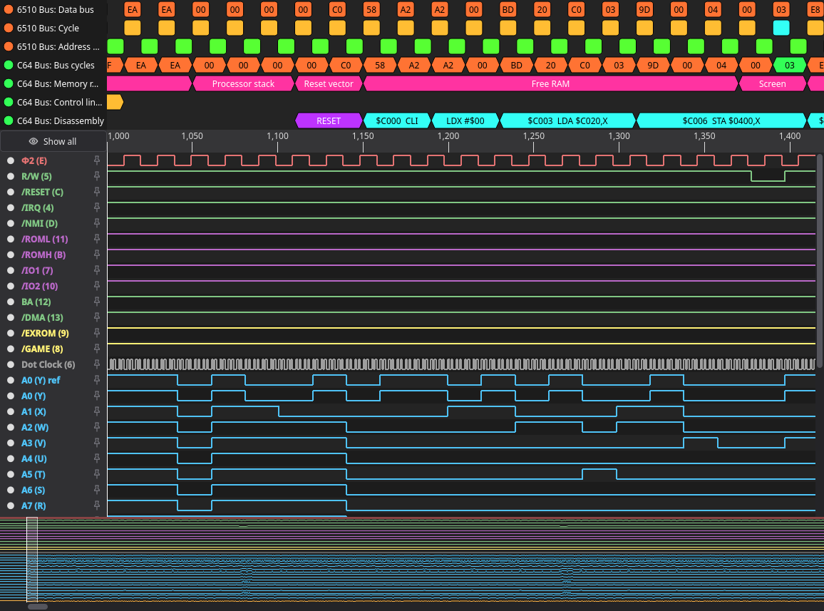
Options: address format (hex/decimal), memory regions on or off, where the bus is read (the 6510 takes the data at the falling Φ2 edge; this application can look back one sample, other hosts read at the edge), a read offset in samples, and whether to disassemble at all.
A capture of the start-up shows the whole 6510 reset sequence: three suppressed stack pushes, the
reset vector at $FFFC/$FFFD, the jump to the KERNAL, LDX #$FF / SEI / TXS / CLD, the CIA
initialisation in IOINIT and the RAM test in RAMTAS. If the addresses and the code do not match a
standard KERNAL, the machine is running a patched ROM.
Open the Disassembly row as a list and filter for JSR to see the call
flow at a glance.
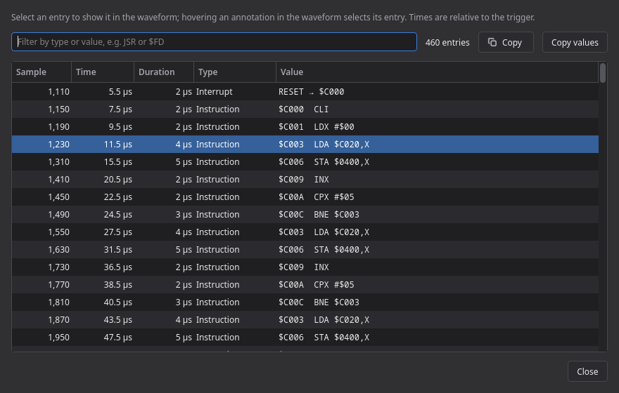
examples/c64-demo.lac is a generated capture (reset, screen output, two CIA interrupts) that
decodes with the same profile — useful to try the decoder before wiring anything up.