Multi device sets
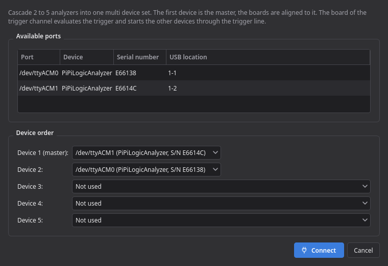
Two to five boards can be cascaded into one set, giving 48 to 120 channels. Connect them with Multiple devices… in the device list and assign the order; device 1 is the master that the other boards are aligned to.
Connect the trigger output of one board to the trigger input of the others (on a Pico: GPIO 0 → GPIO 1). On every board both pins are linked, so all trigger pins form a single line. Ground the boards together.
The board that owns the trigger channel evaluates the trigger and starts the others through that line:
| Trigger | Where it can run |
|---|---|
| Pattern | On any board, within one group of consecutive trigger inputs of that board (Pico: channels 1–21 or 22–24). A pattern cannot span two boards. |
| Edge on a channel | On any board whose firmware drives the trigger output on an edge (the firmware of this project). The dialog only lists those channels. |
| External trigger (every board) | The signal goes to the trigger input of every board and each board waits for the edge itself, so they start together without a delay to compensate. |
The board evaluating the trigger has to capture at least one channel — the dialog says so if it does not. Blast mode and burst mode are not available for a set.
The trigger input is a 3.3 V GPIO. For 5 V signals such as the /RESET line of a C64, use a level shifter or a divider.
The boards are started through a wire, so a slave can begin a sample early or late, and the crystals drift apart by a few samples over a full buffer. After every capture the application corrects this:
-
Reference line (exact): connect one signal of a slave board to a free input of the master
as well and name it like the slave channel plus
ref(the C64 profile usesA0 (Y) refon CH15 of board B). Offset and drift are measured from the two copies. -
Clock (estimate): without a reference line the offset is estimated from a clock channel on
the master (
Φ2,PHI2,CLKorclock).
The status bar and the Alignment row of the capture information name the method and the
correction, e.g. board 2 moved by -1 samples (reference A0 (Y) ref). Capture → Align boards
measures again on a capture opened from a file and lets you choose the method.
All boards of a set need the same firmware version; mixed versions are refused.