Repository navigation
Home
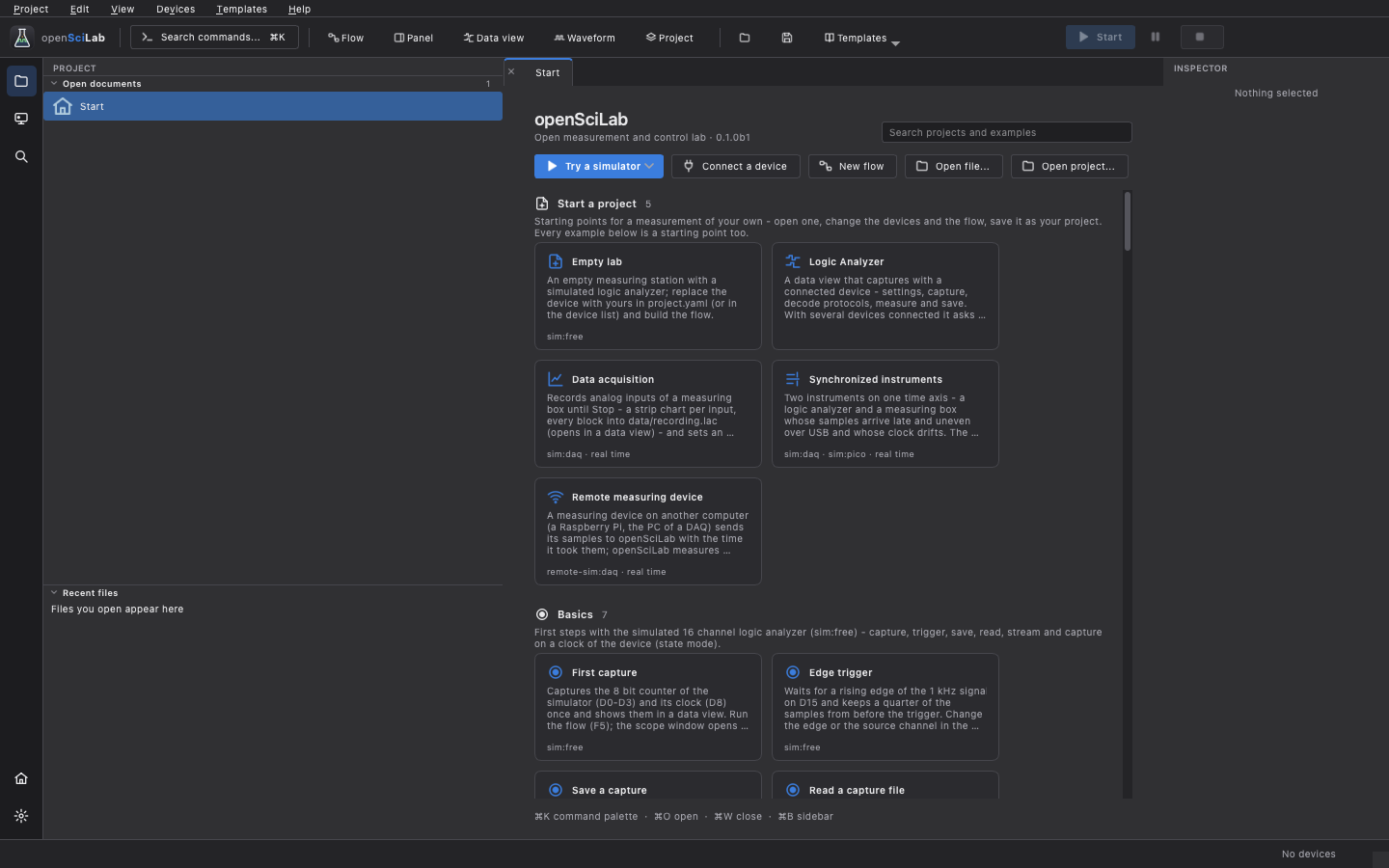
openSciLab is an open measurement and control lab: connect several instruments at once, capture, process, check and generate signals in flows, operate them from panels, write reports - and try all of it with simulated instruments before any hardware is connected. It grew out of PiPiLogicAnalyzer, a logic analyzer for Raspberry Pi Pico boards, which is still there as the data view of the lab. Windows, macOS and Linux; GPL-3.0.
This is a beta (0.1). Every function works with the simulators and is covered by automated tests. Much of the new firmware - the Pico's protocol 8 functions, the Arduino firmware, the Rigol bridge app - has not been checked on real hardware yet. Please report what works on your hardware and what does not.
- Install openSciLab (a ready-to-run build, or from source).
- Get started: the start page, the example projects and a first measurement - with a simulator, no hardware needed.
- Connect your devices and, for a Pico or an Arduino, flash the firmware from the application.
| Page | What it covers |
|---|---|
| Installation | Downloads, first start on Windows, macOS and Linux, running from source |
| Getting started | The window, the start page and templates, projects, a first measurement, settings |
| Devices | The device list, the device card, supported devices and what each can do |
| Firmware | The Pico and Arduino firmware: boards, flashing, self-test |
| Data view | The logic analyzer: capture settings, triggers, streams, analysis, editing, profiles |
| Protocol decoders | Decoding UART, SPI, I²C and 130 more; your own decoders |
| Flows | The flow editor, running flows in real and virtual time, debugging, subflows |
| Nodes | The node families and what they are for |
| Panels and reports | Front panels for a flow; HTML and PDF reports with checks |
| Time and synchronization | Samples of several instruments on one time axis |
| Simulators | The simulated instruments, their signals, wires, faults and limits |
| Remote devices | Measuring devices on other computers, over the network |
| Scripting | The command line and the Python API |
| Files | Capture files, export, projects and their folders |
| Multiple boards | 2 to 5 Pico boards as one analyzer |
| DreamSourceLab DSLogic | The DSLogic analyzers (experimental) |
| The C64 bus | Capturing a Commodore 64 at the expansion port, disassembly |
| Writing drivers | Adding a device, as a plugin or built in |
| Troubleshooting | When something does not work |
The reference documentation lives in the repository: docs/ (flows and every node, command line, simulators, timing, remote devices, drivers, protocols) and firmware/README.md. What changed is in the changelog.
- The inputs of the Pico boards tolerate 3.3 V. A 5 V system such as a Commodore 64 needs a level shifter or a divider - on the trigger input as well.
- Flows and panels switch real outputs. Check what a flow drives before you run it on hardware; All outputs safe on the device card and the watchdog of the firmware release the outputs.
- The Turbo Pico images overclock the board beyond its specification.
- Protocol decoders, driver plugins and Python nodes are code that is executed: only use those from sources you trust.
This is a hobby project, not affiliated with Raspberry Pi Ltd, Arduino, DreamSourceLab, RIGOL or Agustín Giménez Bernad (gusmanb). It comes without any warranty; see the disclaimer.
The Pico logic analyzer hardware, its capture firmware and the original software are the work of Agustín Giménez Bernad (gusmanb), shared under the GPL; this project started from his version 6.5. The protocol decoders come from sigrok.