Repository navigation
Devices
This page covers the instruments openSciLab works with: which devices are supported and what each can do, how to connect them over USB or the network, the device list, the device card with its tabs, and the overview of the connected hardware.
| Device | Connection | What openSciLab does with it | State |
|---|---|---|---|
| Raspberry Pi Pico, Pico 2, Pico W, Pico 2 W, RP2040-Zero, LogicAnalyzer Interceptor | USB or WiFi, with the openSciLab Pico firmware | 24 channel logic analyzer (28 on the Interceptor) up to 100 MHz (200 MHz with the Turbo images), streams over USB, trigger sequences, state mode, 2 to 5 boards as one analyzer; GPIO, PWM, pulses, analog inputs, monitor, pattern generator, square wave, UART/SPI/I²C | version 8 not yet tried on hardware (the 7.x capture firmware it extends is in use) |
| Arduino Uno, Nano, Mega 2560, Uno R4 Minima, ESP32, ESP32-S3 | USB, with the openSciLab Arduino firmware | logic analyzer of its pins (buffer, stream, state), analog inputs, GPIO, PWM, monitor, pattern / square / arbitrary waveform generator (DAC on the R4 and the ESP32), UART/SPI/I²C | not yet tested on hardware |
| DreamSourceLab DSLogic Plus, U2Pro16, U3Pro16, U3Pro32 | USB, with the DSView firmware | logic analyzer up to 1 GHz, streams, record to disk, adjustable threshold | experimental, tested on a U2Pro16 (DSLogic) |
| Rigol DHO900 series (e.g. DHO924S) | network: SCPI, or the openSciLab bridge app on the instrument | 4 analog and 16 logic channels in one capture, large captures arriving progressively, the built-in generator | not yet tested on the instrument |
| Measuring devices on other computers | network, with the Python package openscilab_device
|
values, sampled signals, outputs and commands with the time they happened | beta (Remote devices) |
| Simulators | built in | everything above, several at once, wired together | ready (Simulators) |
The firmware of the Pico and Arduino boards belongs to openSciLab; how it gets onto a board is on the page Firmware. New kinds of devices can be added as drivers or plugins, see Writing drivers.
openSciLab never asks which model a device is. Every device reports what it can do (its capabilities), and the device card, the capture settings and the nodes of a flow offer exactly that. The Details tab of the card lists what a device reported.
The device list is the Devices section of the sidebar: click Devices in the activity bar on
the left, press Ctrl+Shift+D, or choose Devices → Show the device list. It has two parts that
open and close with a click on their header:
-
Connected – the devices openSciLab has open, each in a few lines that follow what it does (every second while the list is shown):
- a coloured dot for its state (connected, simulated, busy, error, disconnected), its name and what its capture does: Ready, Armed, Receiving 45 %, Failed, Disconnected;
- how it is connected (
sim:pico · simulated,pico:/dev/ttyACM0); - the settings of its next capture: rate, samples, channels, trigger, stream – those of the capture bar of its data view, else the ones it keeps; a device without captures lists what it offers (GPIO, monitor, generator, ...);
- a bar with its load: how much of the device memory the capture uses (memory 25 %), how much of the link a stream (link 40 %; from 90 % the bar turns orange: the stream may overflow), or how much of a running capture arrived (received 45 %). A device read in a process of its own adds what that process takes of a processor core (process 12 % CPU).
A click opens the device card. A right click offers Device card, Add to the flow (a device node in the active flow), Show data, Disconnect and Disconnect all devices...; the button in the header of the part disconnects all of them as well.
-
Available – what can be connected. A double-click connects an entry. The button in the header (Look for devices again) and Refresh below the list look for devices at once.
| Entry in Available | What it is |
|---|---|
| Autodetect | the Pico board that is plugged in; with several boards, Autodetect (2 analyzers) asks whether to combine them (Multi device sets) |
openSciLab Pico on /dev/ttyACM0, S/N … |
a Pico board with the openSciLab firmware on this serial port |
Arduino on COM4 (…) |
an Arduino board, also clones with a CH340, CP210x or FTDI chip |
DSLogic U2Pro16 (USB 2, 1:4) |
a DSLogic analyzer with its model, USB speed and bus position |
Rigol DHO924S at 192.168.1.20 |
an oscilloscope whose bridge app announces itself in the network |
climate (remote, 192.168.1.30, ± 0.4 ms) |
a measuring device on another computer that has connected to openSciLab |
| Network device... | a Pico W or Pico 2 W over WiFi (asks for its address) |
| Multiple devices... | 2 to 5 Pico boards as one analyzer |
| Rigol oscilloscope by address... | an oscilloscope that does not announce itself |
| Remote devices (off): settings... | opens Settings → Remote devices; while remote devices are switched on it reads Remote devices: port 24050...
|
| Simulators (with the number of entries) | the group of simulated devices; a click opens or closes it |
Below the list, Hardware... opens the connected hardware. When a Pico is plugged in that is in bootloader mode or runs other firmware (MicroPython, for example), a notice appears with Install firmware.... If a device cannot be connected, the reason shows as a banner in the device list instead of a dialog.
Settings → Devices sets how often the list looks for devices (unplugged ones are noticed then), whether the simulators are listed, whether devices on USB are read in a process of their own (on by default: nothing else the application does can make a stream overflow) and whether that process runs with a higher priority.
From the list. Plug the board in; it appears under Available the next time the list looks (or press Refresh). Double-click it. Opening runs in the background, so the window stays usable while a board or a network address is slow to answer. The device card opens when it is done.
From the menu. Devices → Connect... (Ctrl+Shift+K) or Connect a device on the start
page shows the dialog Connect a device with everything that can be connected, in three groups:
Detected, Add by hand and Simulators. Choose one and press Connect.
Over USB on Linux your user has to be in the dialout group (see
Installation); a DSLogic needs a udev rule (see DSLogic).
A Pico W or Pico 2 W over WiFi. Install the WiFi image of the firmware (Firmware), connect the board over USB once and press Network settings... on the Details tab of its card: Access point, Password, Device address and Port, then Save to device. After a restart the board joins the network. Then connect it with Network device...: the dialog Connect to a network analyzer asks for Address and Port. Over WiFi a board captures into its buffer; streams need USB.
A Rigol oscilloscope. With the openSciLab bridge app running on the instrument it appears in the list by itself. Otherwise use Rigol oscilloscope by address...: port 5560 is the bridge app, port 5555 the instrument's own SCPI server (slower, no progressive transfer). How to install the bridge app is on the page Firmware.
A device on another computer connects to openSciLab, not the other way round: see Remote devices.
A board with old firmware is not opened. openSciLab asks Firmware update needed and, with Update firmware..., shows the board in the connected hardware with the update that fits it.
Next start. Settings → Startup → Connect the devices of the last session again connects them when openSciLab starts (off by default).
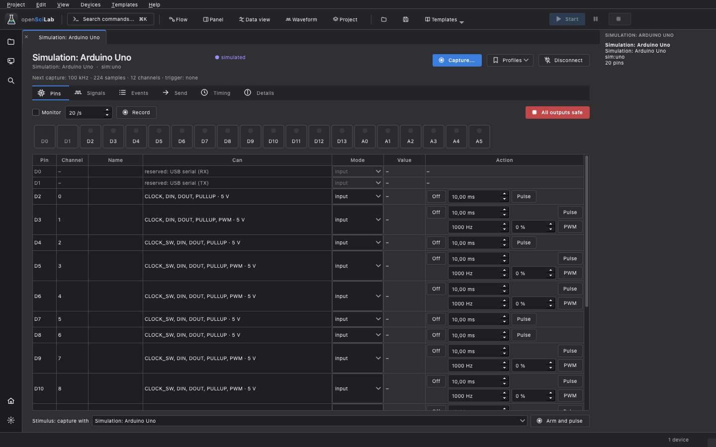
Every connected device has a device card, a document of its own. The header shows the name, the state, what the device is (kind, address, firmware) and these buttons:
- Capture... – opens the data view of the device, where its captures are set up, started and shown (Data view). Only devices that capture have it.
- Profiles – load saved capture settings for this device, save the current ones, the standard profiles.
- Disconnect, or Reconnect when the device was unplugged, disconnected or stopped answering.
Below the header a line names the settings of the next capture (rate, samples, channels, trigger). Problems with the device – it was unplugged, a capture failed – appear as a banner here.
The card shows only the tabs the device has:
| Tab | Shown for | What it holds |
|---|---|---|
| Remote | remote devices | the latest value of every input, fields for the outputs, buttons for the commands, how well the device's clock is known |
| Pins | every device | the pins with their channel, name and abilities; with GPIO also mode, value and actions |
| Signals | simulators | what the simulator simulates, its wires and its emulated USB link (Simulators) |
| Events | simulators | what the simulated device did, with its time |
| Send | devices that send UART, SPI or I²C with their own hardware | send frames and see what a target answers |
| Cache | a Rigol with the bridge app | the captures the app keeps, with Refresh, Delete, Delete all and Set limit |
| Timing | devices that capture | how the samples are placed in time and how well |
| Details | every device | the device's functions, capture limits, capabilities, board, firmware, connection |
For devices with GPIO a strip above the table shows the pins with their level; a click selects a pin. The table has the columns Pin, Channel, Name (from the capture settings), Can (the pin's abilities and logic level) and, for devices with GPIO, Mode, Value and Action. Reserved pins are greyed out with the reason, e.g. the trigger pins of a multi device set.
-
Mode of a pin:
input,input_pullup,input_pulldown,output,pwm,analog– as far as the pin can. - Actions: a switch (Off / On), a pulse of a set width (Pulse), PWM with frequency and duty cycle (PWM), a voltage on an analog output (Set).
- The first time a pin drives, openSciLab asks (Drive it): a 5 V output can damage a 3.3 V input, and two outputs against each other short-circuit.
-
All outputs safe turns every output back into an input; on this tab
Escdoes the same. - Monitor reads the inputs periodically (readings per second next to it) and shows levels and voltages, analog ones with a short history. Record records the monitor as a slow capture in a data view.
- Stimulus: capture with an instrument, then Arm and pulse: arms a capture (on this or another device) and then pulses the selected pin once, so the capture sees the response.
Everything set on a device while one of its captures runs becomes a marker in that capture.
The Timing tab shows how the samples of the device are placed on the time axis and how well, and holds what makes it better:
- the Sample clock: Own sample clock (offset and drift are fitted) or Shared or external sample clock (only the offset is fitted);
- the latency, measured with a loopback: choose the Output and the channel it is wired to, the Rate and the Mode, then Measure (a simulator is wired with Wire them (simulator)); measured latencies are kept until Forget the latencies;
- a sync output on a pin (Pin, Seed, Start);
- This computer's clock... (Settings → Time), and two buttons that open the matching examples.
All of it is explained in Time and synchronization.
- Device – buttons for what the device can be asked to do, as far as it can: Capture settings..., Self-test..., Test signals of the board..., Network settings..., Restart device..., Restart into the bootloader..., Update firmware..., Reconnect and Copy the details. Self-test and test signals are described on the page Firmware.
- Capture limits – how many samples a capture in the device's buffer can hold, by the number of channels (Min. pre-trigger, Max. pre-trigger, Max. post-trigger, Max. total).
- Capabilities – Facets (what the device offers: Capture, GPIO, Monitor, Analog inputs, Analog outputs, Generator, ...), Reported (the capabilities as the device sends them) and Unlocks.
- Connection and details – board, firmware version and build, chip, the connection (port, USB data or network address).
Copy the details puts everything on this tab on the clipboard – please add it to a bug report.
Disconnect on the card, in the right-click menu of the device list or in Devices → Disconnect closes a device. openSciLab asks first while a capture runs, outputs are driven or a running flow uses the device.
Devices → Disconnect all devices... (also the button in the header of Connected) closes every device after one question that names each device and what disconnecting it interrupts. Running captures and recordings stop, outputs are released.
A device that was unplugged is marked disconnected, one that stopped answering is marked with an error. Its card stays open and offers Reconnect.
| Entry | What it does |
|---|---|
Connect... (Ctrl+Shift+K) |
the dialog Connect a device |
| Show the device list | the Devices section of the sidebar |
| Device card, Show data, Disconnect | each opens a list of the connected devices |
| Disconnect all devices... | see above |
| Connected hardware | the overview below |
| Install or update firmware... | the same overview, to install firmware |
| Forget multi device sets... | forget the remembered order of multi device sets |
| Simulate faults | disconnect, delay or restart a simulated device, overflow its next stream (Simulators) |
Devices → Connected hardware (or Hardware... below the device list) lists every board and device connected to this computer – open or not – with the firmware on it:
| Column | Content |
|---|---|
| Device | e.g. openSciLab Pico, Board in bootloader mode (RP2040), Raspberry Pi board, a DSLogic |
| Connection | port, drive or address |
| Firmware | version and board, e.g. firmware 8.0 · Raspberry Pi Pico · RP2040
|
| State | up to date, update to 8.0, board not recognised or no openSciLab firmware |
Each row has its buttons: Device card for an open device, Open for one that is not open yet,
and Install firmware, Update firmware or Reinstall firmware for Pico boards. Choose an
image... writes any .uf2 file by hand, Refresh looks again. Simulated devices are not listed
here. The page Firmware describes installing step by step.
openscilab-cli devices lists the connected devices, openscilab-cli info <address> describes
one. Every device has an address, e.g. pico:/dev/ttyACM0, pico-net:192.168.1.5:24000,
arduino:COM4, dslogic, rigol:192.168.1.20 or sim:uno; flows use the same addresses. See
Scripting.