2. Assembly Guide EN
Language: Deutsch | English
Contents
- Introduction
- Shopping List
- Projector Choice
- The Gate
- The Lens
- The Light Source
- Projector Conversion
- Installing a switching PSU
- Install optical sensors
- Cut‑outs
- Raspberry Pi Preparation
- Scan‑Controller Setup
- Woodwork
Building this scanner isn’t difficult, but it’s still a fairly large project. You should plan for two to three free days (or more evenings). It’s a lot of fun, and the results are fantastic! 🤩
You don’t need any special tools or special skills. You also don’t need particular electronics or computer knowledge.
Patience is often worth more than the most expensive tool collection!
Here is what you need to buy if it isn’t already in your parts box. The links are only example sources; it’s often worth searching a bit for a better deal.
All items below are also available (with combined shipping savings) in my Lectronz shop as long as demand and stock allow:
- Scan‑Controller as fully assembled board
- Armor Case enclosure for Raspberry Pi 4B — other cases may fit, but this one is inexpensive, fanless, and fits perfectly.
- 50 cm camera ribbon cable — optional but recommended. The included 20 cm is often too short; longer is more flexible.
- micro SD‑card, 32 or 64 GB is plenty. I recommend SanDisk Extreme (Gold).
- 27W USB‑C power supply — Note: the small 15W supply often included is too weak for stable operation; I don’t recommend it.
- M42 to C‑mount adapter
- M39 to M42 adapter ring
- Heatsink for the LED — 40 × 40 × 20 mm fits well in the lamp house.
- 5″ HDMI LCD display with 800×480 pixels. It fits as a “lid” for the Scan‑Controller.
- High‑power LED with CRI > 95 — 4000–6000 K is ideal.
Also required:
- An old (ideally broken) projector with DC motor (Noris or similar, more on projector choice below) – €25
- Raspberry Pi 4B with 4 GB RAM – €65 (If necessary, the 2 GB version will also work, but scanning will be approximately 10-20% slower. 1 GB is definitely not sufficient, and 8 GB offers no advantages.)
- Raspberry Pi High Quality Camera with C‑Mount – €60
- C‑mount extension rings, total about 50–65 mm depending on adapter depth (e.g. AliExpress): it’s worth stacking smaller rings until it fits – €10
- A used M39 enlarger lens with 50 mm focal length (eBay) — I use an EL‑Nikkor 2.8/50, but there are many other good lenses – €20
- PTFE sheet approx. 1 mm thick as diffuser between LED and gate
- If the projector transformer hums loudly, is defective, or doesn’t provide enough voltage for the chosen LED, I recommend a small switching power supply. The MeanWell LRS-50-24 provides 24 V at 2.2 A (52 W), is compact, solidly built, and costs about €10.
- Small parts: Sugru and/or epoxy putty, a few screws, an HT pipe clamp, wood or MDF plate as base
- Thermal adhesive or paste if needed
- Optional small fan for the heatsink if the LED runs too warm
In principle, any projector with a DC motor can be converted into a scanner. (DC motors are found in nearly all projectors that can be speed‑controlled without changing belts, friction wheels, or gears.) The Scan‑Controller simply powers the existing motor until one revolution is completed, then brakes it. That’s fast, simple, reliable, and quieter than a “singing” stepper motor.
Important when choosing a projector is good image steadiness. I recommend a projector that moves the film continuously via a sprocket gear and does not rely solely on the claw. Even though the latter often works surprisingly well when projecting, it can behave differently in the step‑wise operation of a scanner, because the supply reel has to accelerate from standstill on every step. That stresses the film and can hurt steadiness.
My choice for this guide is a simple Noris projector from “Ernst Plank KG, Nürnberg.” These projectors are rather unsexy and thus cheap; they very often have DC motors, use feed and take‑up rollers with slip‑free chain drive, and are made of solid metal where it matters (film path!). Many models (see below) also make it very easy to detect film end for automatic scan stop. They also have another rare advantage: the film pressure is applied from the lamp side, not from the lens side. This avoids focus jumps when film thickness changes, because the emulsion side never changes position. That allows scanning mixed stocks spliced on one reel without refocusing.
Last but not least, these projectors are low on gadgets and electronics and can be stripped down easily.
I’d love to hear about other conversions as well—there’s likely a lot out there. Please let me know!
Special offer: Send me detailed photos and a description of converting another projector (Bauer, Eumig, whatever) for publication on this page, and I’ll refund the cost of the Scan‑Controller on request!
Ideally suited (and shown here) are (at least) these compact Noris models:
- Noris Exclusiv 1000 (black push-button version)
- Noris Exclusiv 2000
- Noris Exclusiv 2000 D
- Noris Record D
- Noris Record D100
- Noris Record SM
- Noris Record SMD
- Noris Record SM1200
- Noris Präsident
- Noris Präsident D
- Noris Record L100 (from serial number 5xxxxx)
Also suitable with minor limitations are earlier models with a universal motor (more on that here):
- Noris Record L100 (serial number < 5xxxxx)
- Noris Exclusiv 1000
- Noris Record L
All models with a “D” in the name can be converted to Normal‑8 film with a few steps—provided the two sprocket rollers and the N8 gate are still in the lamp‑house cover. Convenient! D models are easy to recognize in photos by the front arm, which has a white adapter sleeve for S8 operation.
Not yet tested are the “Noris Norimat” models, recognizable by the cassette recorder attached at the back. If you have experience with these: please get in touch!
Certainly also suitable are the roughly 20 different “Noris Norisound” models, which don’t bring a cassette recorder but provide (now unnecessary) hardware for magnetic sound playback. Remove it if you like! Many of these models are also dual‑format capable without conversion via a switch. They also have a larger reel capacity.
The following is a detailed illustrated guide of the conversion in multiple steps. Don’t worry—it isn’t hard. The guide is long only because I wanted to show and explain every step in detail. :)
To prevent the home‑cinema enthusiast from constantly adjusting the frame line, 8 mm projectors cheat a bit: they crop the film image generously and show only part of what is actually on the film. When projecting that’s helpful (especially with poor steadiness), but when scanning you generally want to see everything that’s on the film (even if it’s not assassinations of American presidents).
Therefore it’s worth filing the gate to a larger opening. This step is optional but recommended and not as hard as it sounds. With time and care, it’s much easier than it seems—so go for it!
According to SMPTE S149‑2004, the Super 8 frame exposed by the camera is 5.69 × 4.22 mm. The projector is specified at only 5.36 × 4.01 mm and in practice often even smaller. Many cameras expose slightly wider than the standard allows, so there’s a lot of hidden image to discover!
Overall, the gate should be enlarged to about 6.2 × 4.6 mm, leaving margin on all sides and allowing MAX‑8 scanning. The goal is to gain about 0.8 mm in height and 0.6 mm in width. Precision isn’t critical, but remember: what’s removed is gone—so file carefully and adjust later if needed.
If a dual‑format D projector is being converted, the N8 gate should be enlarged to about 4.1 × 5.2 mm—also about +0.8 mm in both directions.
On Noris projectors the gate is easily accessible. First tilt the lens carrier forward. On D models you can simply slide the gate off to the side; on pure S8 models, loosen the large slotted screw:

The gate mounted on the lens carrier can be removed with a single screw.

Left: unmodified gate on the lens carrier. Right: already enlarged gate (without lens carrier, from a D model). Top right is the narrow claw slot.
For the rework it’s very helpful to use a head‑mounted loupe or even a reflected‑light microscope—you can actually see what you’re doing, and the magnification makes you automatically more careful. It also works without. With a set of needle files and two hours you can do it even as a beginner. I recommend a step‑by‑step approach as shown in the image sequence below. If you file “across the whole width,” you quickly lose track of how far you’ve gone. Also: avoid slipping. The film path should not be touched; masking it can help!

The unmodified gate

On the right you can see that about 0.4 mm was removed at top and bottom. This is the target height.

The same amount was removed on the left. The remaining bridges help with orientation and are removed last.

Corners are still rounded; I square them at the end with a thin triangular file.

To the right there’s not much room before the perforation. Remove only a little here.

Toward the sound track side you can remove quite a lot.

But don’t go past the middle of the shoe (left), so film pressure remains flat.

If needed, straighten a bit for the eye. The right angle can be checked well by projecting without film.
It’s a good idea to periodically check progress by reinstalling the gate in the projector and using a film scrap to ensure everything is visible around the edges.
That’s the rough work—now it’s time to finish so there are no scratches. If you have them, use scraping files to remove burrs. Otherwise a dental pick works well. Also check the back of the gate for burrs!

My favorite files—coarse on the left, fine on the right. Hardware‑store files work too.
After that I carefully polish everything with a felt bob on a Dremel at low speed. I swear by “Nettoyant Flitz” polishing paste; a chrome polish or similar fine compound works too. Just don’t remove significant material.


No burrs left; edges slightly rounded. Please pay special attention to the corners that extend into the shoe.

The side bearing surfaces are also smooth and flawless. What you see is some remaining polishing paste. 🙂
Then remove polishing paste and debris very thoroughly (rinsing, compressed air, whatever) and polish with a clean, dry cotton cloth to a mirror finish. If you don’t trust visual and tactile inspection, mark a piece of white leader with a whiteboard marker and pull it through the film path. It will show any burr immediately.
If you’re a perfectionist, mask the gate and spray a little matte black paint from the back to avoid reflections on the inner edges of the gate.
Done!
To project the film image onto the sensor of the camera module, this scanner uses something highly optimized yet readily available: an enlarger lens.
These lenses are plentiful from well‑known manufacturers and often cheap, because they are less suitable for normal photographic use—not because of the M39 thread, but because they are designed for close‑up work. Enlarger lenses operate in the near field (the photo paper is almost never more than a meter from the negative), show almost no distortion, are razor‑sharp, and vignette little—especially when the sweet‑spot aperture is used. This is typically achieved by stopping down the lens by two to three full stops from wide open. For example, an f/2.8 lens often performs best around f/5.6 (or f/8). Above and below that the image quality decreases again.
Enlarger lenses for 35 mm film almost always have an M39 thread. With a simple adapter ring this can be extended to M42 and then fits directly into the M42‑to‑C‑mount adapter. To bring the film image into focus on the sensor, we increase the distance between camera module and lens using extension rings.
Choosing the extension rings requires some experimentation; a total around 57 mm should be about right and will capture slightly more than the (enlarged) gate. You can adjust later by adding or removing rings. With 57 mm of rings it looks like this for me:

The frame line is still visible at top and bottom, as well as the edges of adjacent frames. A longer extension zooms in, a shorter extension shows more “around” the frame.
The only real criterion I recommend for choosing an enlarger lens is: use at least a four‑element lens. The cheapest three‑element lenses are noticeably worse. For digitizing 8 mm film, the very common 50 mm focal length works perfectly.
The assembly of the optical system is straightforward and described in detail below.

From left to right (shopping list above):
- The Raspberry Pi HQ Camera module
- C‑mount extension rings with a total length of about 60 mm
- A C‑mount to M42 adapter
- An M39 to M42 adapter ring
- The enlarger lens with matching lens cap
- The projection lens of the projector (we only need its sleeve as a mechanical guide)
Everything from the camera module to the enlarger lens is simply screwed together:

Be careful not to get dust on the sensor. You can clean it, of course, but because the sensor is small (11 mm diagonal), every tiny dust speck is visible. So blow out the extension rings and M42 adapter and assemble them straight from the packaging. The enlarger lens then seals the tube and the system becomes dust‑tight. The ribbon cable can be removed from the camera module by carefully sliding up the connector, which makes handling easier and avoids cable damage.
To keep the system stable when attached to the projector (you wouldn’t believe how small vibrations can cause visual earthquakes), we use the projector lens as a mount. Remove all its lenses. These lenses can usually be cracked apart with a firm twist.
Note: If you don't like cracking lenses or don't have one, you can also use a 3D printed part here. Some approaches can be found in the 3d Parts Folder of the repository.

Only the outer part (middle) is needed; the rest goes to the parts bin. The empty tube will later be bonded to the front side of the lens cap. To let light pass through the tube, a hole must be drilled in the lens cap.
Note: My friend Sebastian Bock couldn't bring himself to "butcher" his lens and therefore contributed a 3D-printable tube. The print files can be found here.

I used a 30 mm Forstner bit — it doesn’t have to be pretty or straight. You can also drill multiple small holes in a circle and then break out the center. No one will see it in the end!
 Tube, lens cap, and the sawn‑out piece. A screw‑on lens cap is best (and most stable), not a push‑on one.
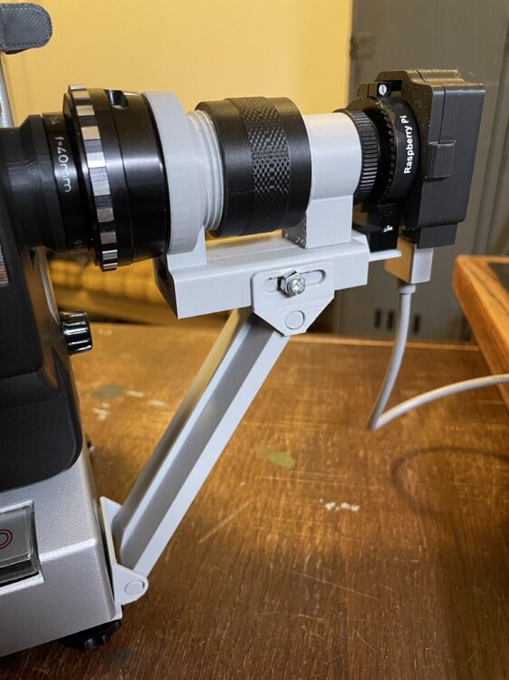
Later, once connected (see below—be patient!), the optical system looks like this:
 Here 60 mm of extension rings are installed, which wasn’t quite enough for Max‑8...
 Sebastian's luxury approach, 3D printed, with fine focus tuning. STL files can be found in the repository.
There are many options for light; I’ll show two that I’ve tested—first a simple (good) one and then a rather over‑engineered one that I enjoy a lot. :)
Recently I also tried a simple PTFE disk as diffuser and got excellent results. Others prefer point light sources for the Callier effect (enhanced edge sharpness) and remove scratches digitally afterward. There’s lots of room for experimentation here!
The light source described here is very easy to build, inexpensive, needs no active cooling, and is close in quality to the integrating sphere (see below) that I previously built (with much more effort). Comparative tests to see whether the integrating sphere hides scratches and streaks even better are still pending. The COB LED used here is a Cree CXB1304‑0000‑000C0ZB2L5A in the 9 V version. This LED has excellent CRI, a very even spectrum, and high efficiency, so it wastes relatively little heat. It’s also inexpensive.
 As a carrier for the COB LED, a 40 × 40 × 20 mm heatsink (PC accessory) is mounted where the projector bulb holder used to be. You can glue the heatsink with thermal adhesive, but I prefer to screw it so the light source can be changed later. The two existing holes (center of image) can be reused for mounting.
 Align the heatsink on the front edge (so it’s straight) and mark the two holes from behind with a pencil.
 Hole spacing is exactly 30 mm here, but it can differ between projectors...
 Two M2.5 holes were drilled with an HSS bit. It helps to drill through two or three fins so the screw has enough clearance. I quickly cut M3 threads because I didn’t have suitable M2.5 screws.
 To let my M3 screws pass through the projector chassis, I drilled the existing M2.5 holes out to 3 mm. The paper underneath catches the aluminum chips—those should not end up in the mechanics...
 The two M3 screws (8 mm long here) are inserted from the motor side and screwed into the heatsink.
 With a flashlight you can determine where the LED should sit to be centered in the gate. (It doesn’t need to be super precise due to the diffuser.) Mark the center with a pencil.
 The LED carrier board is 13 × 13 mm; use a set square to mark the outline on the heatsink.
 The LED is now glued with a small amount of thermal adhesive and fixed temporarily until cured. Alternatively you can mount it with thermal paste and two screws clamping the board. Note: orient the LED so the wires point down and back into the projector, away from the motor shaft.
 I cut the diffuser from a piece of PTFE sheet, which is available cheaply on eBay. The sheet here is 1 mm thick and about 20 × 50 mm, so it doesn’t interfere with the claw. PTFE cuts well with a sharp utility knife. If needed, lightly matte with P400–1000 sandpaper.
 The diffuser is mounted from the back to the gate. I used tape so the gate can still be cleaned from behind.
 The heatsink with the LED is now coated with a thin layer of thermal paste on the side and screwed to the chassis. In the image I measured temperature after 20 minutes: this LED can run passively without a fan; the heatsink stays around body temperature. (I’d add a fan above 50°). At 450 mA the forward voltage is 8.8 V and after 20 minutes the heatsink is only 32°. These parameters look ideal for continuous operation. At 600 mA (and UF = 9.1 V) it is only 37° and about 50% brighter. Light quality and color temperature at those conditions still need testing.
 LED in operation, dimmed to 5 mA for the photo
Done!
I admit I overdid it with my first light source—curiosity got the better of me. I coated a ping‑pong ball on the inside with a varnish made from barium sulfate and polyvinyl alcohol, creating a miniature integrating sphere. The biggest advantage of such a mixing chamber is perfectly diffuse light at the exit pupil, making scratches, dust and streaks much less visible—plus higher light efficiency if you need it (usually you don’t).
The detailed guide is here.
This guide shows the conversion of a projector using a Noris as an example. Almost any suitable projector can be converted; the steps are basically the same:
- Remove lamp and lamp holder
- Optional: create space by removing unnecessary parts (fan, switch, electronics)
- Optional: remove shutter — only needed for an integrating sphere
- Optional: remove projector electronics
- Optional: reuse transformer / install a switching PSU
- Install optical sensors
The following photos are from a Noris 100D; models are similar.
 First remove the lamp and the lamp socket with its terminal.
 The lamp holder is unscrewed. There are different versions, but all are simply screwed on.
These steps are optional. You can leave all of this in the projector and simply disconnect the motor. The shutter must be removed only if you want to use an integrating sphere as light source, because it must be as close as possible to the gate.
With an LED and diffuser, you can skip all steps up to Remove projector control.
 Under the lamp holder you’ll see a screw that holds the fan housing to the rear. Remove it.
 Remove the lower screw of the fan housing (from the back).
 The fan housing can now be pulled off. It is no longer needed.
 The fan wheel is secured with a circlip. Carefully pry it open and slide it off.
 To remove the fan wheel, slide the motor backward by loosening the front clamp screw.
 Now you can pull off the fan wheel. (If the motor belt needs replacing, this is a good time to slip it over the shaft.)
 Some Noris models have a microswitch above the motor shaft, actuated by a centrifugal mechanism (to reduce lamp voltage in slow‑motion or still mode). To remove it, first unscrew the switch itself. Cut the wires.
 Then remove the entire switch bracket.
 Now you can remove the heat‑protection filter as well. Not needed.
 The shutter is now exposed so you can cut off its three blades.
 This is easy with a Dremel and cut‑off wheel. I keep the Dremel stationary and slowly turn the motor shaft by hand to avoid binding. (Caution: sparks; wear safety glasses.)
It helps if a second person vacuums the grinding dust. Otherwise metal filings stick to all magnetic surfaces (motor!) and combine with grease into an abrasive paste. Alternatively cover all other projector parts (I forgot in the photo).
 The removed blades
 Now cut off the remaining ring so it doesn’t interfere with the integrating sphere. Be careful of the claw cam and lubrication felt! It helps to keep the Dremel fixed and rotate the shaft by hand.
 The ring can now be removed from the shaft. There is now space for the ping‑pong ball!
 The only cables we absolutely need are these two at the back of the motor. They should be extended or replaced with longer ones. Ensure sufficient wire gauge.
 If a centrifugal switch remains on the motor shaft (e.g. for a heat filter or lamp brightness limiter), wrap it with tape or a zip tie so it doesn’t rattle later.
Removing the projector control is only necessary if you want to reuse the built‑in transformer or install a switching PSU inside the projector. You can instead connect an external PSU directly to the Scan‑Controller board—in that case skip to Install optical sensors.
 The board is held by a screw in the middle, accessible from below.
 To remove the board, loosen the switch block by removing the two screws that hold it to the base.
 Remove the rectifier too; it gets in the way.
 Now you can wiggle out the switch block. Press all four buttons at once and cut all wires to the board.
These steps are optional. Only reuse the original transformer if you’re familiar with electrical safety. Depending on age, expect strong hum at no load. The simpler and safer way is to disable the IEC inlet (remove it and close the hole) and use a small off‑the‑shelf switching PSU (e.g. MeanWell LRS‑50‑24), see next step.
 The brown wire from the IEC inlet is connected to the black wire of the voltage selector—either with an insulated Wago connector, a new direct wire, a switch, or a fuse holder (which the Noris unfortunately lacks). Observe electrical safety!
The remaining secondary wires all come from the rear end of the transformer. The reference wire is black on all Noris projectors I’ve seen, but should be measured. Typical color coding (relative to black):
- Brown: 24 V (no‑load approx. 30 V): motor supply (after rectification and smoothing). This rail is ideal for the Scan‑Controller board!
- Yellow: 12 V, 10 A: lamp supply. Usable, but low for fast winding; can usually be disabled.
- Blue: 8.5 V: reduced lamp voltage for slow motion or still operation
- Models with direct 18/24 switching (e.g. SMD) often have an additional motor‑voltage tap for 18 fps (color not standardized).
If you prefer not to use the projector transformer, disconnect it completely—cut all leads as short as possible, including at the voltage selector, which is not needed with a modern switching PSU.
 The suggested Meanwell PSU fits nicely in the projector. It can be fixed with a screw or double‑sided tape on the projector base.
 To power it, remove the IEC inlet and solder fresh cables. The protective earth (yellow‑green) should always be the longest wire so it tears last in case of strain.
 Phase, neutral, and earth are screwed to the PSU, and the IEC inlet is reinstalled. The ~40 cm black‑red cable later supplies the Scan‑Controller.
The Scan‑Controller needs two sensors: one to detect each motor‑shaft revolution, and one to detect film end. The Scan‑Controller has two optical sensors on board that can be mounted flexibly. Break off the two fingernail‑sized boards at the perforation in the top right. You can score with a cutter first.
Note: Sebastian Bock and Sandro Proske have contributed 3D-printable sensor mounts. The print files can be found here. It also works directly:
 A proven mounting method uses an M2 screw and nut and a ~13 mm M3 standoff. Simple screws also work.
 Drill a 3 mm hole in the bracket next to the motor pulley, roughly centered.
 Pause and/or use cutting paste so the drill doesn’t overheat.
 The mounted sensor, its “eye” about 2–3 mm from the pulley.
 Stick a small piece of matte black tape on the pulley; the reflective sensor detects the completed revolution. Position the tape so the claw has finished the frame step and any shutter is open. You can adjust the tape position later if needed.
 The optical sensors have three pins: ground (pin 1, marked), output (middle), and supply +. The three wires can be loosely braided and will later be connected to the Scan‑Controller.
Extend the film inlet shutter with Sugru or epoxy putty. It should look about like this (gray here):

Extend the black plastic knob forward by about 1 cm. This will become the reflective surface for the film‑end sensor. From above with the film path open it should look like this:

On the left of the extension, the film must enter freely; on the right there should be a roughly right‑angled edge toward the projector front. The optical sensor will be mounted here later.
Sugru can be carved nicely after it cures, so you don’t need high precision.
 It’s practical to mount a piece of header pin strip (“male header”) or stiff wires to the film‑end sensor, because on the Noris it is mounted at 90°.
 Position the sensor so that with film inserted it has 3 mm distance to the swung‑out inlet shutter. I extended this black shutter (which is moved by the auto‑threading loop former) with Sugru. White Sugru would be better than my dark gray because nothing adheres to Sugru reliably—and we need a reflective surface for the sensor...
 Without film inserted, the sensor no longer sees the little piece of paper and reports film end.
 I attached a 3‑pin Dupont socket with epoxy putty so the sensor can be replaced and repositioned. Any attachment method is fine. You can also replace the sensor with a fork light barrier or a mechanical switch that senses the film from the side.
 I later trimmed my Sugru extension of the film inlet shutter so that film end is reliably detected even with the record‑brush holder (see below) extended. This is easy with a utility knife.
 At the marked white spot, drill or file a small notch for the sensor cables.
 The same on the underside, centered and facing forward. The cables will later exit here. (In the image, motor cables and power for the light source are still missing.)
 The entire cable bundle (with lamp cable here) is tied with one or more zip ties for strain relief. Route the cables so they don’t interfere with moving parts. I recommend labeling each cable bundle with a tape flag.
 The fully converted projector with the back cover reinstalled.
Done!
 Open the camera connector (up and then to the side) and insert the camera cable. The contacts must face away from the USB ports. Close the connector.
 The cable must be fully inserted.
 Route the other end of the cable through the top of the Armor case.
 Remove the protective films from both sides of the three included thermal pads and place them on the corresponding chips with tweezers. Avoid touching and deforming them.
 Place the top shell and flip the assembly.
 Place the bottom shell and tighten the four screws diagonally to press the thermal pads.
 Insert the micro SD‑card as shown. The image is written beforehand as a .tgz file using Balena Etcher (free).
 Attach the other end of the camera cable to the camera. The contacts must face the lens.
 Place the Scan‑Controller board onto the 40‑pin header from above and press down evenly and carefully.
 Check that the connector is seated and both rows are in the sockets.
 *Now plug in the Raspberry Pi power supply to USB‑C. Note: during this first boot nothing visible happens for a while; keep power connected. Just wait. Please ignore the micro‑HDMI cable already connected here. *
 After 1–2 minutes the system is set up and at least the green power LED should light, possibly more.
 Turn all four blue trimmer pots fully to the right (like closing a faucet) with a small slotted screwdriver. These pots have no hard mechanical stop, so keep turning until you hear a faint click. This sets current and voltage to the maximum limits so you don’t damage anything. Then turn the “Current” and “Voltage” pots back two turns to the left, so they’re not fully closed and we can later set a voltage (no current → no voltage…).
Set the two knurled pots “RunSpeed” and “StepSpeed” roughly to the middle.
Now connect and power the supply voltage for motor and LED (in this example the output of the Meanwell PSU installed in the projector) to the “36V in” terminal block of the Scan‑Controller. Push the orange spring terminals all the way back and insert the wires deeply.
(If you still use the projector transformer, switch the projector on now. The supply voltage can be up to 36 V and AC or DC. It’s advisable to use the 24 V winding of the transformer. The key is that it provides enough voltage for the LED and enough to spin the motor.)
Optional: First set the LED fan voltage if a fan is used. Connect a multimeter (DC V) to + and – of the “Fan” terminal. Press the “Lamp” button on the far left of the control panel; a small white LED indicates the projector light would be on. Turn the “Fan Speed” trimmer to set a suitable fan voltage (e.g. 5 V). The range is about 3.8–11.3 V.
Next, set a low forward voltage for the projector LED to safely adjust the short‑circuit current without melting meter leads (the LED driver can deliver >150 W!). Connect the multimeter (DC V) to + and – of the “LED” terminal. With the white LED lit, turn the “Voltage” pot left until you read about 3–4 V.
Now set the maximum current of the constant‑current source—the most important parameter for LED lifetime. Use the LED datasheet for ideal current and best CRI. For my YUJILED it’s 400 mA. Switch the multimeter to current (A, DC), ideally starting at the highest range (often 10 A). You may need to move the meter leads to the correct jack. Then turn the “Current” pot left until the desired current limit is set (e.g. 400 mA).
Since the projector LED will certainly need more than 3–4 V forward voltage, measure voltage again at the LED terminal (DC V—reconnect leads if needed) and set the “Voltage” pot to at least the maximum forward voltage of the LED (20 V for mine). This value is not critical; you could turn it all the way up since LEDs should be driven with constant current and will settle their forward voltage. But setting it to the datasheet maximum adds extra protection at no cost.
Now connect the power LED (“Lamp”) and optionally the fan (“Fan”) to the + and – terminals. Pressing the “Lamp” button should toggle both. This is a good time to let the lamp run for half an hour and measure temperature—adjust fan speed if needed. More airflow is better than an overheated LED! If you want, you can measure the actual operating current by connecting the LED not to + and – but to the unlabelled middle terminal and –. Place the current‑measuring multimeter (A, DC) between the middle pad and the “+” pad; it’s then in series with the LED and measures actual current. It should be slightly less than the set maximum, never more.
 Setting 400 mA output current yields about 9 V forward voltage on its own: the datasheet is right. :)
Now is a good time to secure the “Voltage” and “Current” trimmers with a drop of lacquer or glue so they can’t be accidentally turned. The LED will thank you with long life.
Next, temporarily wire the other terminal blocks as well:
- “Motor” goes directly to the projector’s DC motor wires. (If rotation is wrong later, swap the wires.)
- “End” connects to the film‑end sensor (observe polarity)
- “Shaft” connects to the motor‑shaft sensor (observe polarity)
Now is a good time to optimize the sensor positions. The film‑end sensor must be positioned so that with film inserted (or the inlet shutter swung out) the red “No Film” LED on the Scan‑Controller goes off. The motor‑shaft sensor should make the red “Shaft” LED light when the shaft is past the claw’s top dead center and the sensor sees the black mark. The exact stop position is not critical as long as the claw step is complete—just don’t miss pulses.
Once everything is wired and the sensors are correctly positioned, you can use the transport buttons (like on a tape deck) to move the film continuously or frame‑by‑frame in either direction and stop. The speeds for step and continuous run can be set independently with their respective pots, which is useful if you want to rewind.
After this short test, disconnect the Raspberry Pi from power (important) and unplug the projector from the scanner.
 Unscrew the two front rubber feet.
 Another view of the internal wiring.
 Remove this screw; it holds one side of the projector transformer. Don’t worry, it will be replaced soon. :)
 For mounting the projector you need 2× M6×30 (or longer), 1× M4×30 (or longer), and 2–3 large washers per screw.
 Three holes are drilled in the base plate (here 22 mm MDF). Use this drilling template to mark the holes. Align the dotted corner to the board edges and mark the three holes.
 I didn’t have a drilling template yet... I countersank the three holes with a 25 mm Forstner bit so the screws don’t protrude underneath. Alternatively you can screw feet under the plate.
 Then drill through with an 8 mm bit (I used a 10 mm by accident—also works).
 Insert the screws with a washer through the holes...
 Flip the plate—now you can see how the projector fits.
 On the top side, shim the projector with washers so the protruding screws underneath have clearance.
 The projector should be parallel to the base plate, otherwise the optics can’t slide properly. Experiment with washers on the rear small screw until it fits.
 This is roughly how the optics are supported. My MDF blocks have (somewhat arbitrary, don’t ask) sizes of 106×125 mm (large) and 106×80 mm (small). The exact size doesn’t matter; we want weight and flatness.
For my first prototype scanner I screwed very strong magnets (30×6 mm round) into the bottom of the support block and attached a thin metal sheet to the base plate. Our delivery driver asked me, somewhat puzzled, why my parcel was stuck to the ceiling of his van... Magnets are not really necessary here, and they actually make fine-tuning the optics harder rather than easier compared to relying on weight alone.
 Glue three large and one small block (yes, one fewer than shown above!) with wood glue and clamp them.
 Now connect all (previously labeled) cables to the Scan‑Controller. Observe polarity. Push the wires deep into the open terminal blocks so they hold securely.
 Now screw in four M3 standoffs (20 mm or longer)...
 ...they hold the 5" display as a “lid.”
 Connect display USB power to one of the black USB ports (the slower USB 2.0 ports).
 Connect the display HDMI port to one of the Raspberry Pi’s micro‑HDMI ports. Some newer display revisions swapped connector side, so the included 20 cm cable may be short. Use a longer one if needed—I like the ultra‑flat flexible FPV cables with angled connectors. 20 cm often still works.
 A small glued‑on strip supports the Scan‑Controller and display at a practical ~45° angle. This improves usability; the display also doesn’t have a huge viewing angle.
 The optics are supported by an HT pipe clamp that fits perfectly around the C‑mount/M42 adapter.
 Drill a 7 mm hole in the “step” of the base so the steep side of the 8 mm screw for the clamp can be tightened securely.
 The projector’s lens sleeve and our optics should be at the same height. In my photo I had already glued the enlarger lens cap to the empty projector lens sleeve, which wasn’t very practical. Better to glue only once the height is correct.
 To check height, press the light button on the Scan‑Controller. You should see the entire gate with a bit of margin. If needed, you can support or fine‑adjust the camera module with a 1/4‑20 UNC screw (standard tripod thread).
 Done!
Done!
 I also recommend adding magnets for a carbon fiber record‑brush so the film runs through it. This prevents dust at the gate very effectively!
 When not in use, the brush can be retracted to keep it clean. For 120 m reels you must remove and reposition it because the Noris is a bit tight there... or clean the film beforehand.
« Overview | User Guide »