Howto Bauer P8 EN
Language: Deutsch | English
The Bauer P8 is ideal for conversion, because the conversion is very simple - and the projector is sturdy, precise, proven, fairly recent, and almost indestructible. It is also still quite easy to find at reasonable prices; I have seen several in classified ads and similar offers from schools, churches, and similar institutions.
The simplest model is enough here, the one that only supports optical sound and 24 fps, because we do not need the shutter blades or the sound unit anyway.
After removing the rear cover, you can already see the DC motor at the bottom, which will continue to be used:
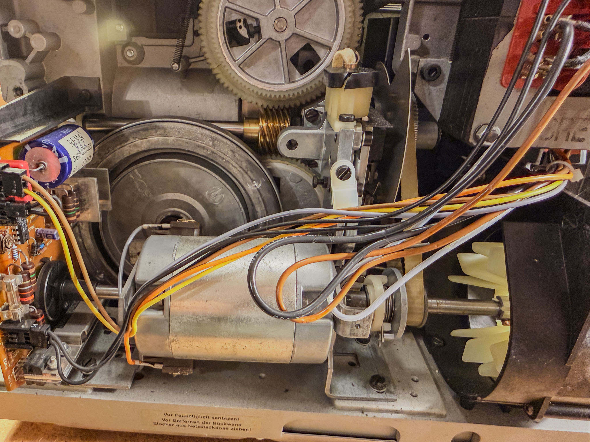 To the left of the motor shaft is the regulator board with the tachometer sensor, which is removed without replacement.
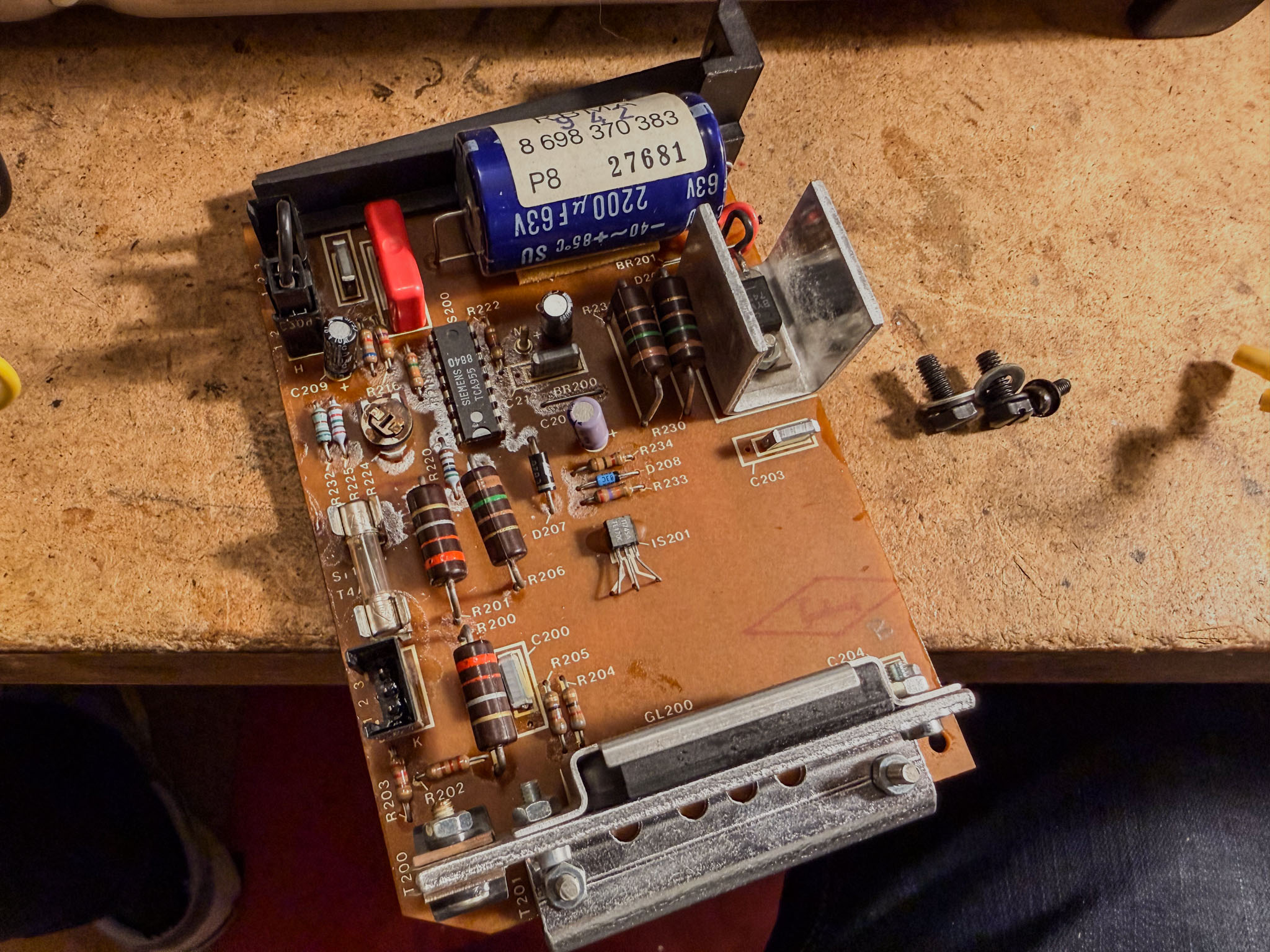 The regulator board is worth keeping as a spare - the TCA955 regulator IC is no longer available new, but is often needed when repairing other projectors.
After this bit of lightening, the complete (and very heavy) transformer is also removed.
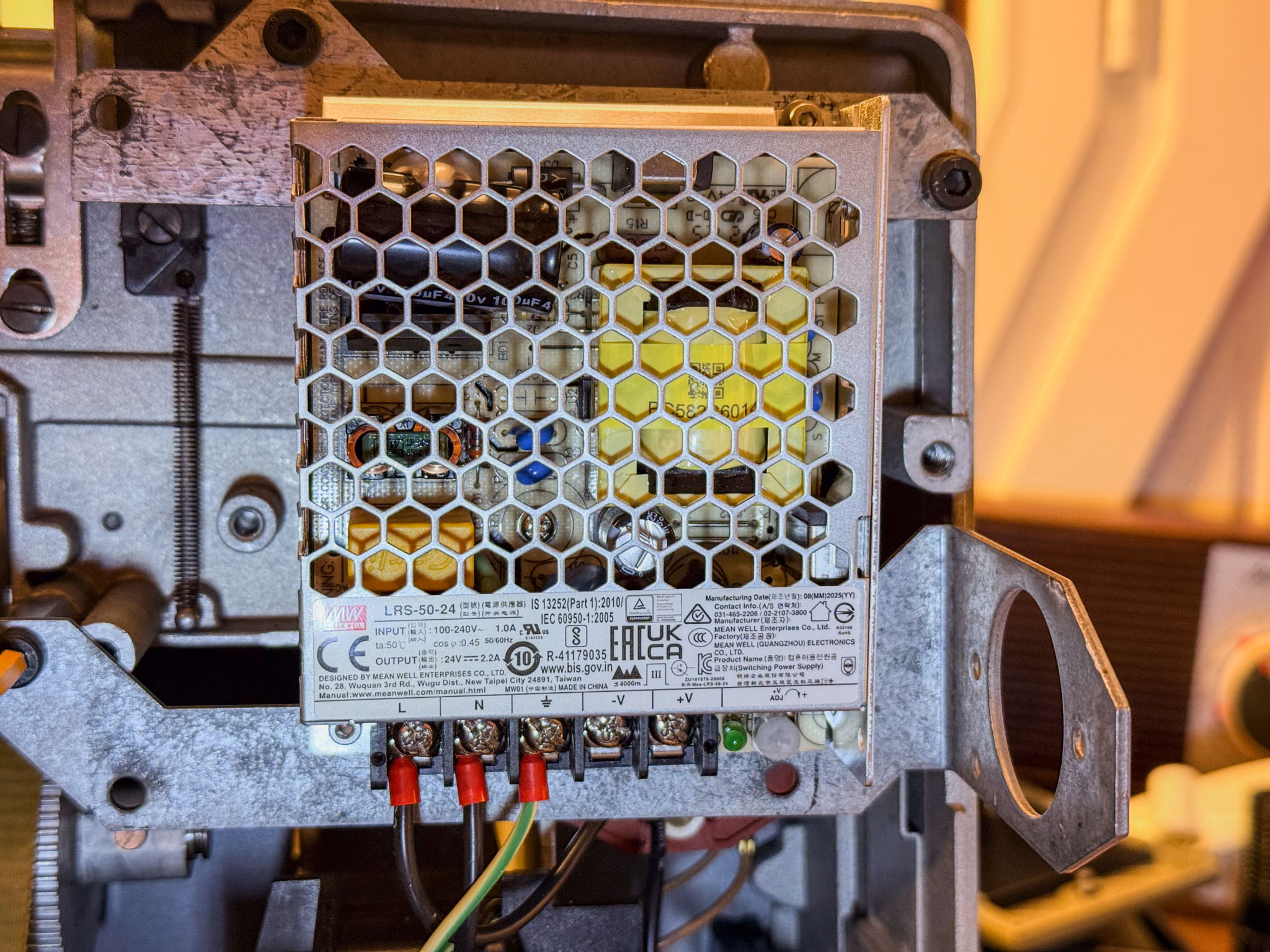
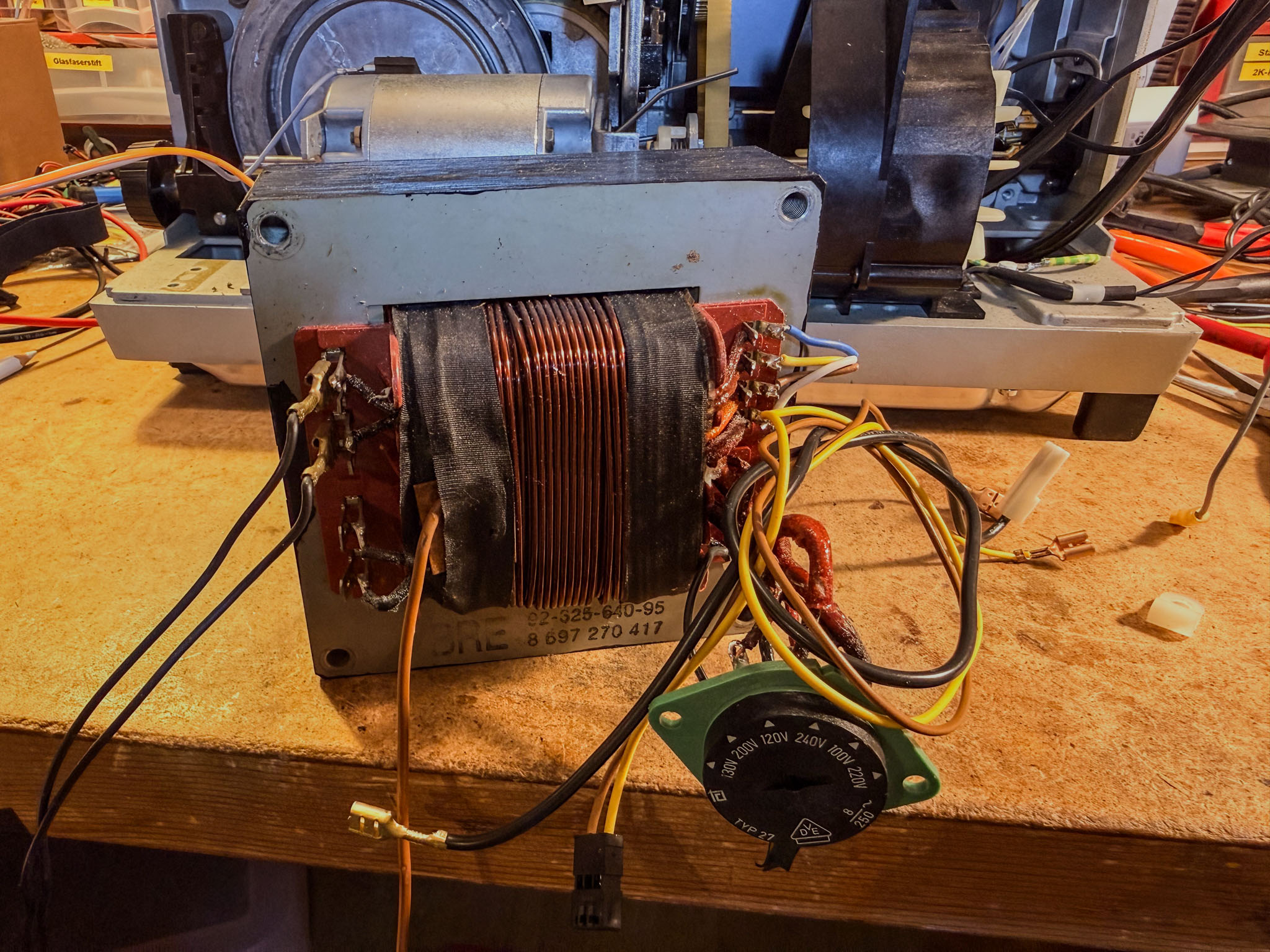 The voltage selector and all connection cables are no longer needed either. The small Mean Well switching power supply fits nicely in place of the old transformer.
The large flywheel for the sound unit's capstan shaft is no longer needed either and frees up the shaft.
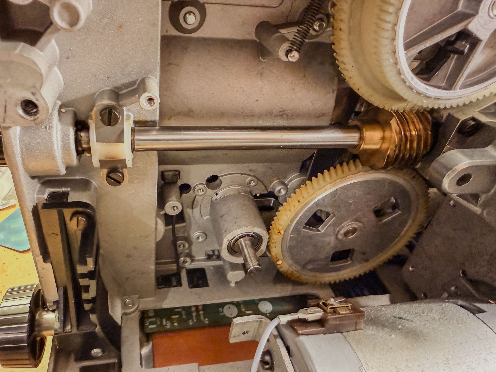 After removing the retaining ring, it can be taken off the shaft and discarded. Sometimes you need to wiggle it a bit or apply some force.
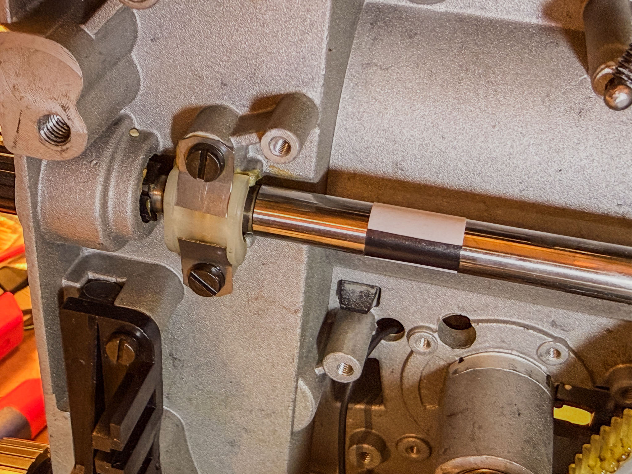
Next, the motor shaft sensor is attached. A white adhesive label around the motor shaft with a deep black felt-tip marker line is enough:
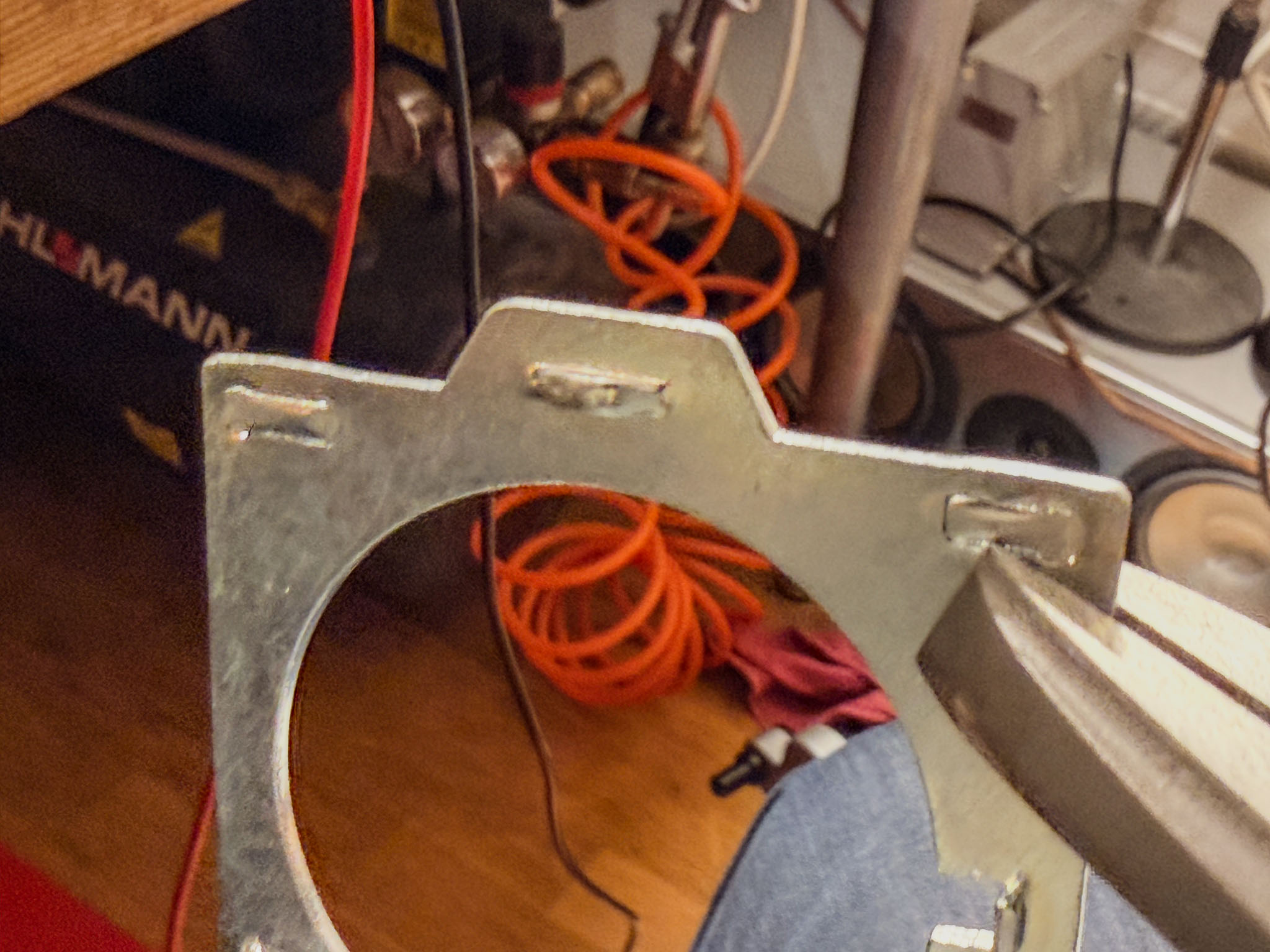
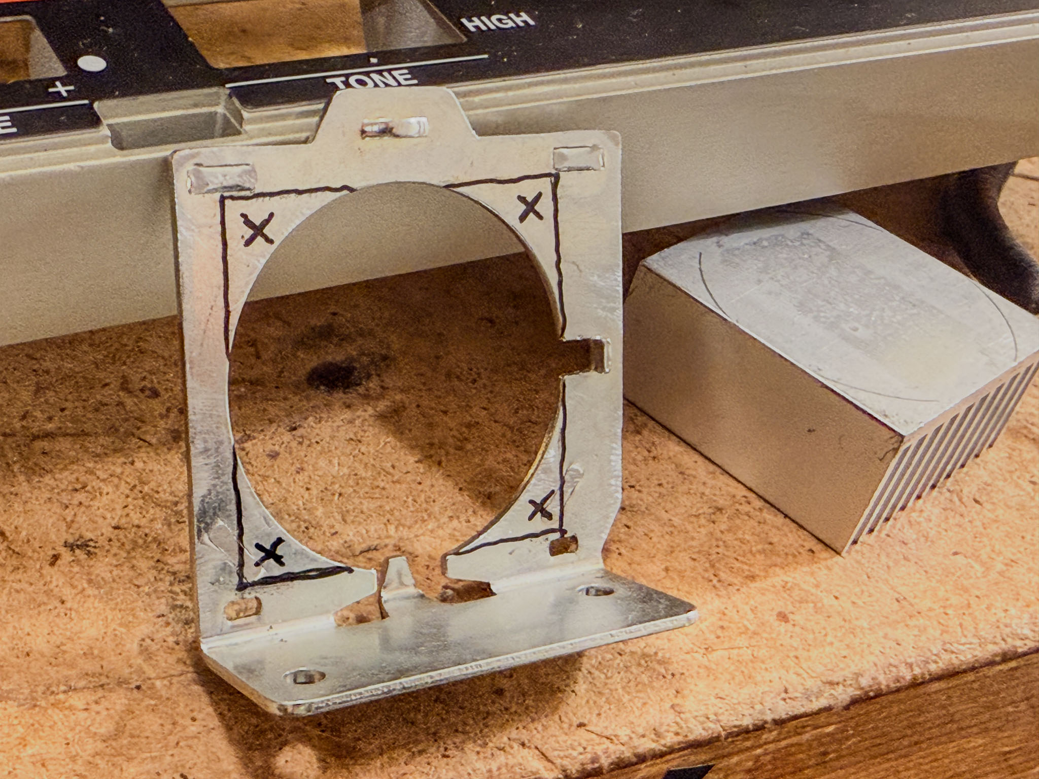
To mount the "eye" in the right place, I made a small plate (a scrap of circuit board, because it was within reach) into a mounting bracket.
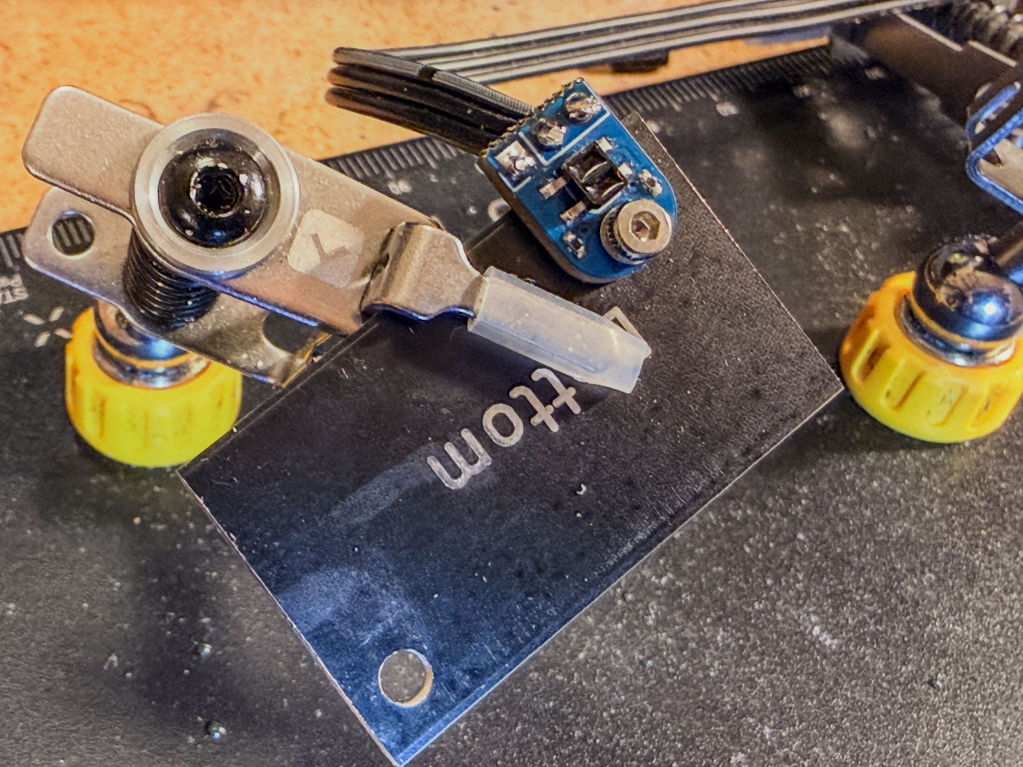 Simply drilled two holes...
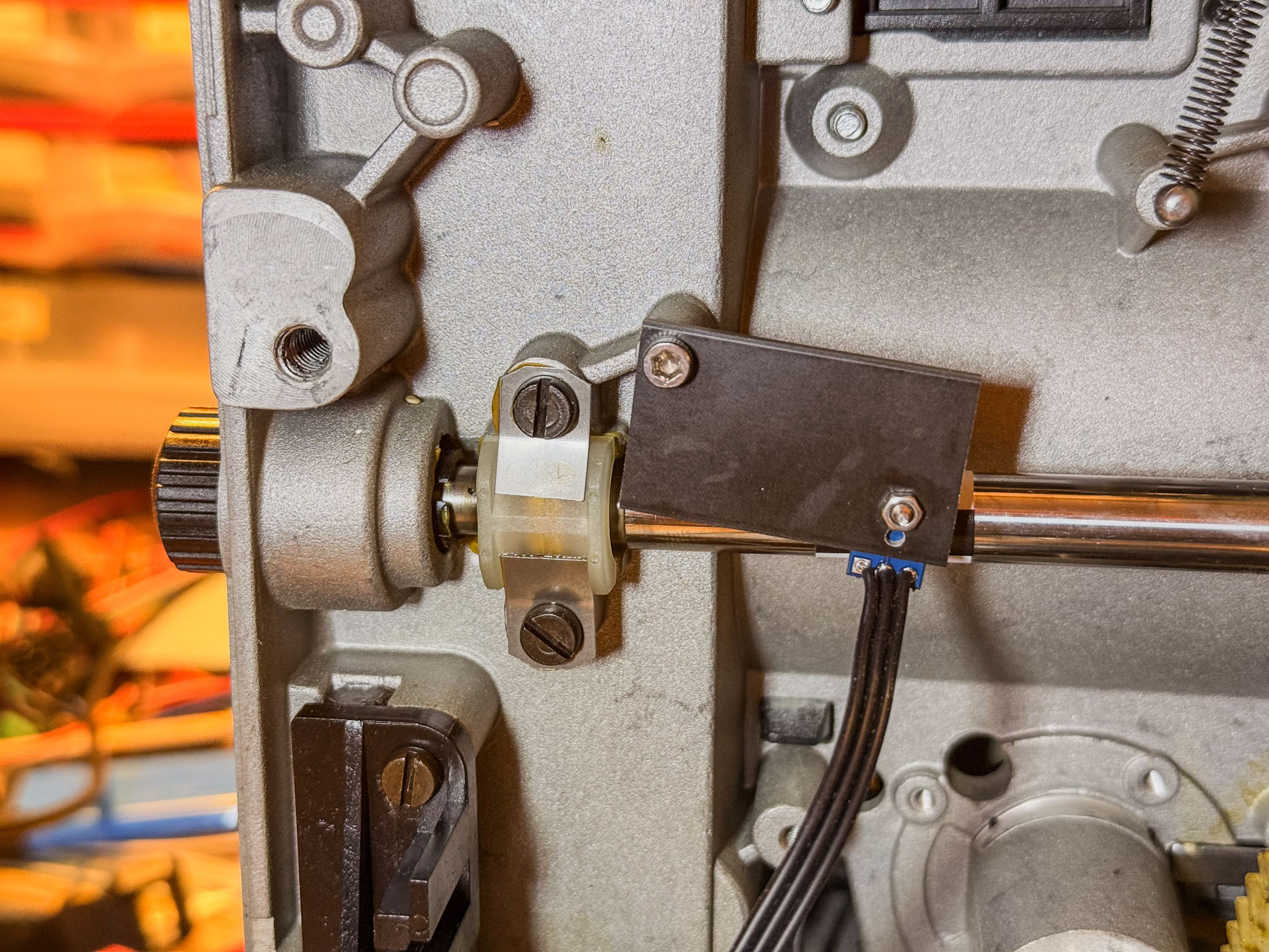 ...and attached it using an existing screw hole.
One step I forgot to photograph: the two shutter blades should be cut off with a cutting disc on a Dremel. They are only in the way and, if not adjusted perfectly, can partly shade individual frames. To prevent the metal dust produced during cutting from dirtying the projector mechanism, generously mask off the projector section in front of the rotary shutter (paper and gaffer tape are enough). It also helps if someone holds a vacuum cleaner right next to the cutting area to suck away the grinding dust.
 The shaft with the shutter blades removed. Conveniently, turn the motor shaft slowly with one hand while holding the Dremel with the cutting disc in the other; this makes removing the blades quite easy.
Next, remove the bottom plate, which is held on with an enormous number of screws. The amplifier board and all its cables can now be removed.
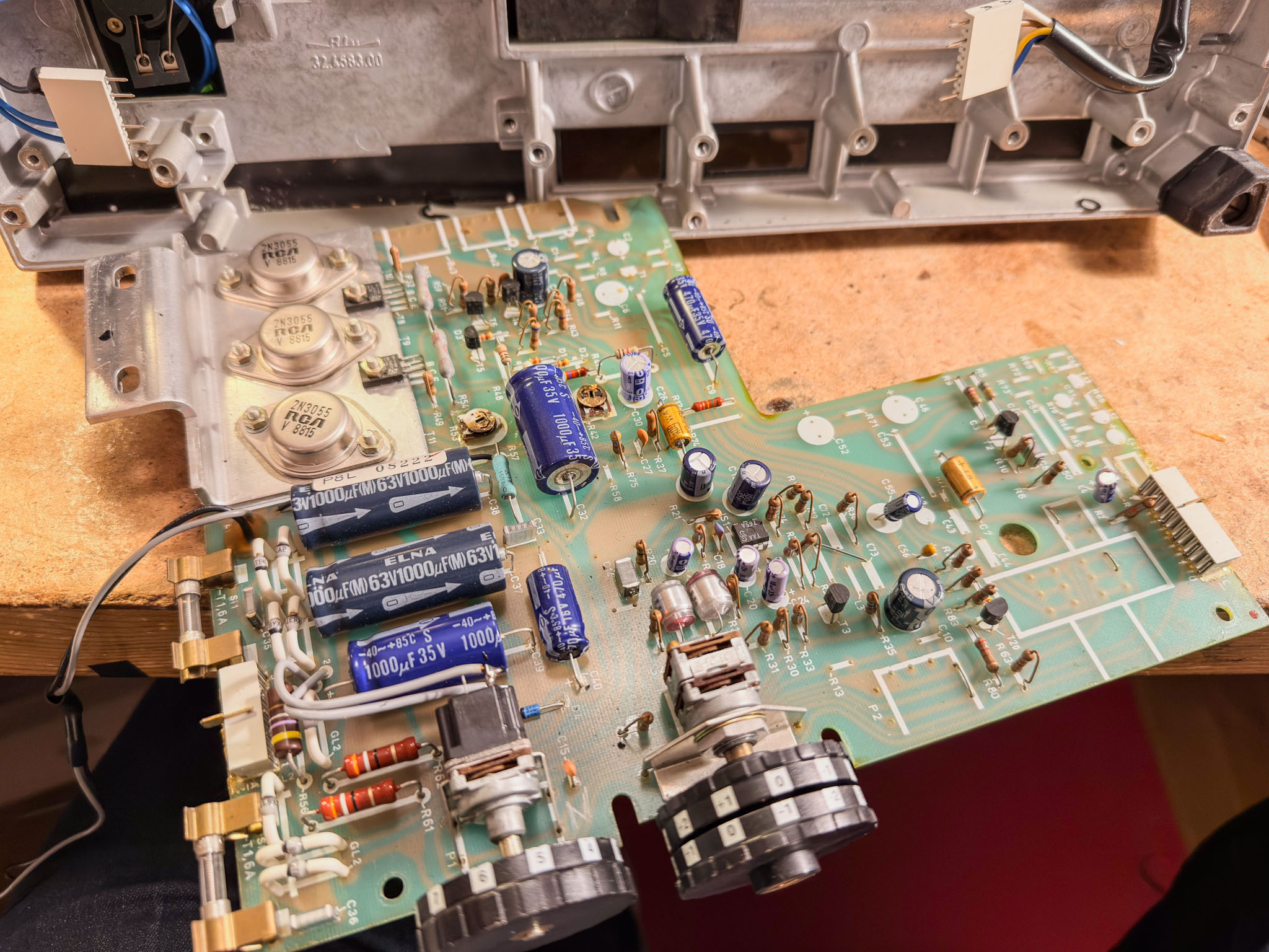 Another spare part worth keeping, if needed: the amplifier board
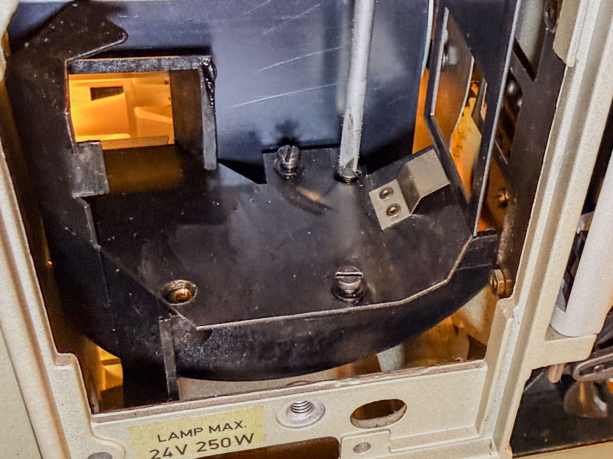
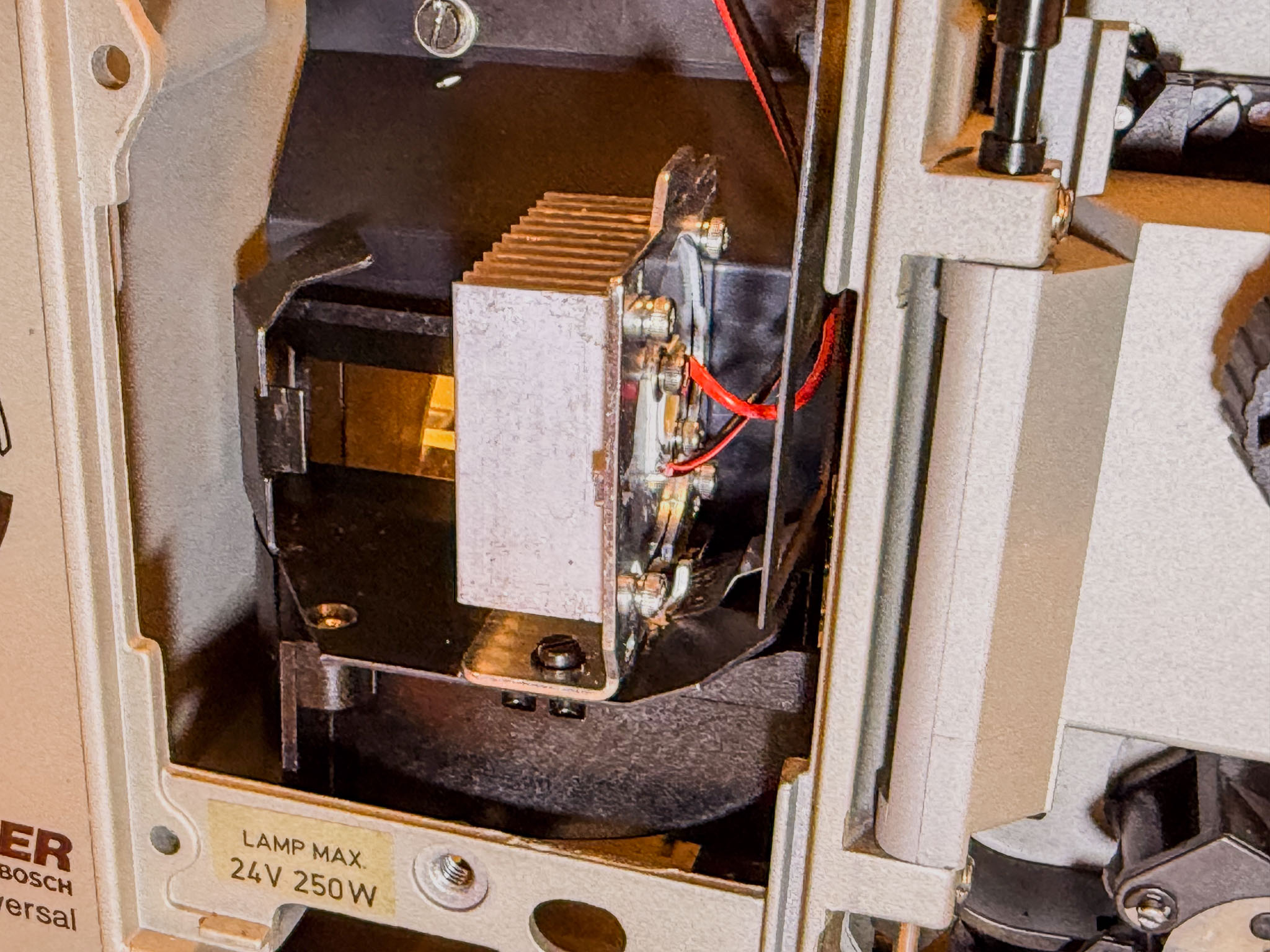
On to the lamp house.
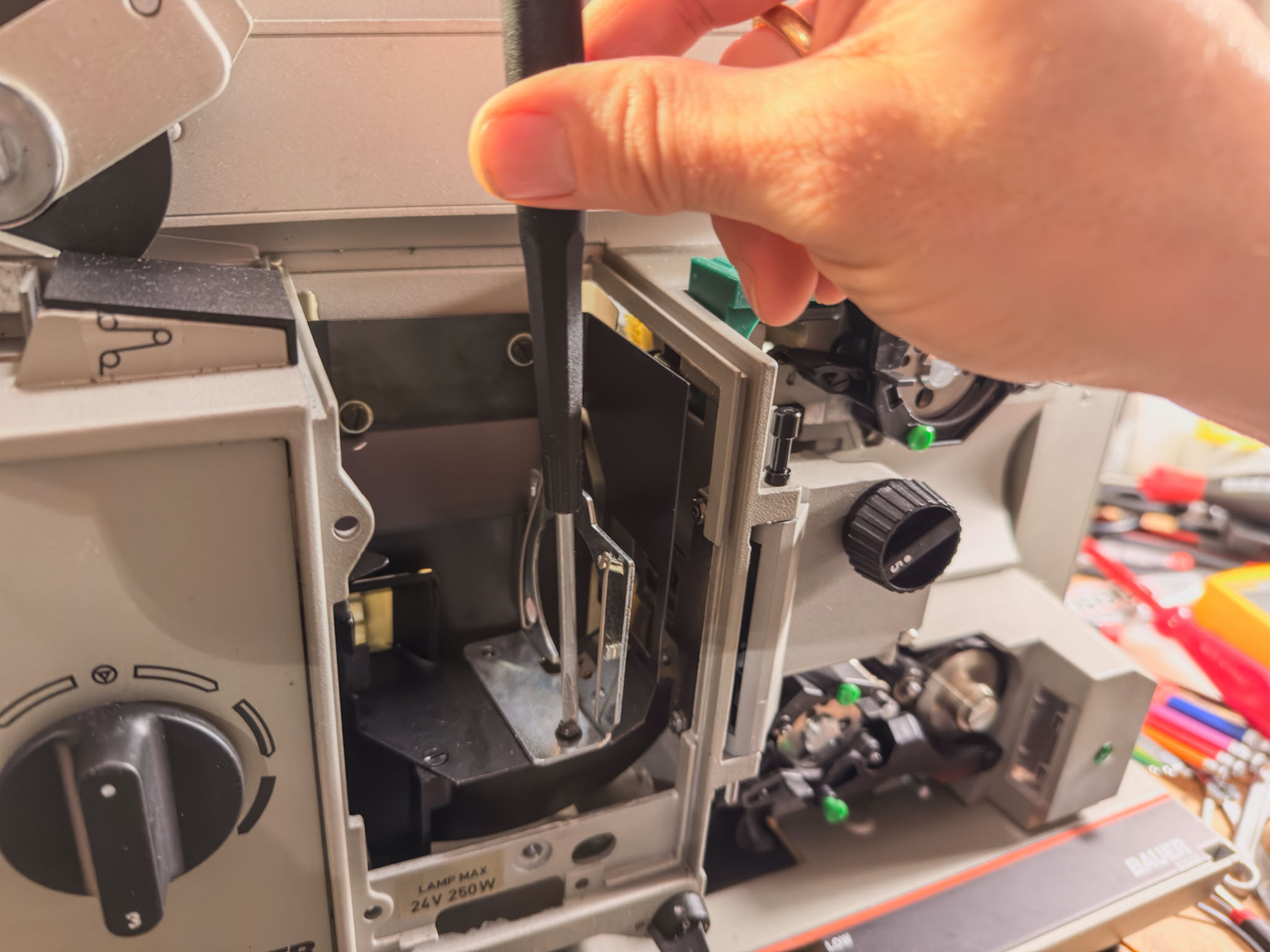 Remove the lamp holder by loosening two screws...
 The tabs that held the projector lamp can simply be flattened again with flat-nose pliers. The goal is to get a flat contact surface.
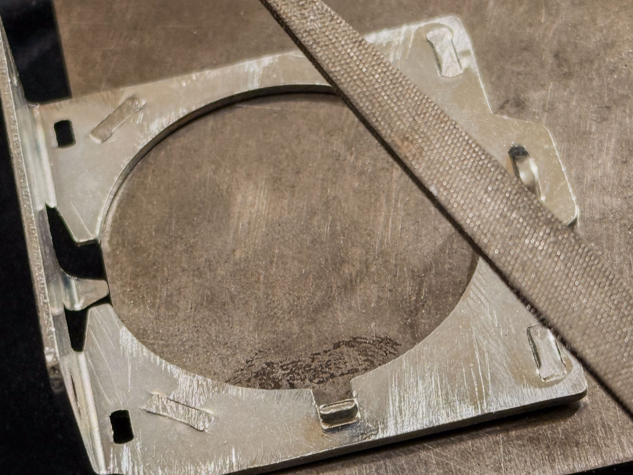 I filed down the last protrusions a little so the lamp holder can conduct the LED's heat well. I do not know whether this is absolutely necessary, but it does no harm.
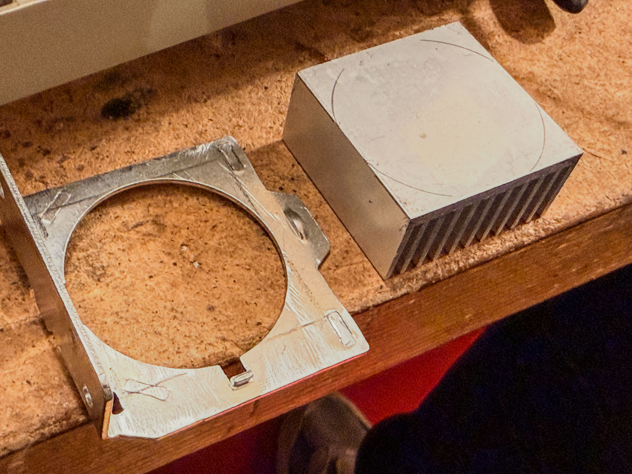
 Markings help position the 40x40 heat sink in the center. Drill the four marked holes with a 3 mm HSS drill bit.
 I also temporarily removed the bottom plate of the lamp house so the heat sink could be fastened tightly to the lamp holder with four screws. Otherwise it is difficult to reach the rear screws.
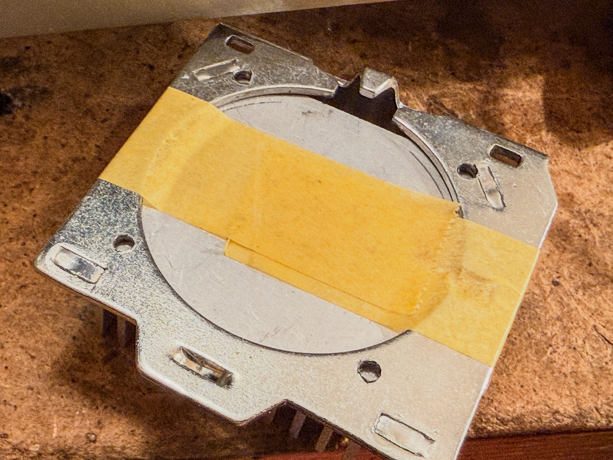 The lamp holder now serves as a drilling template to transfer the four holes accurately to the heat sink.
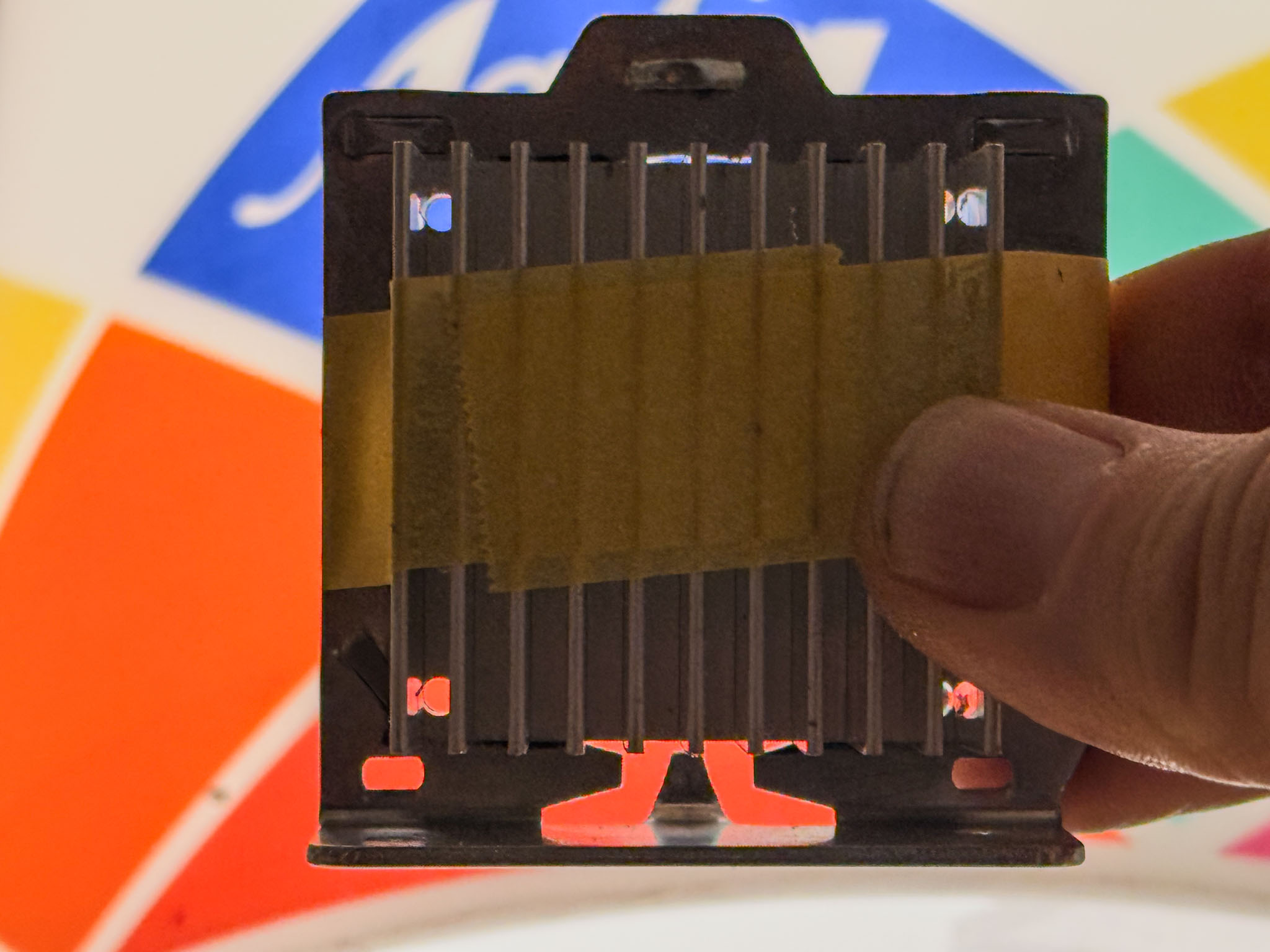 Check against the light: fits!
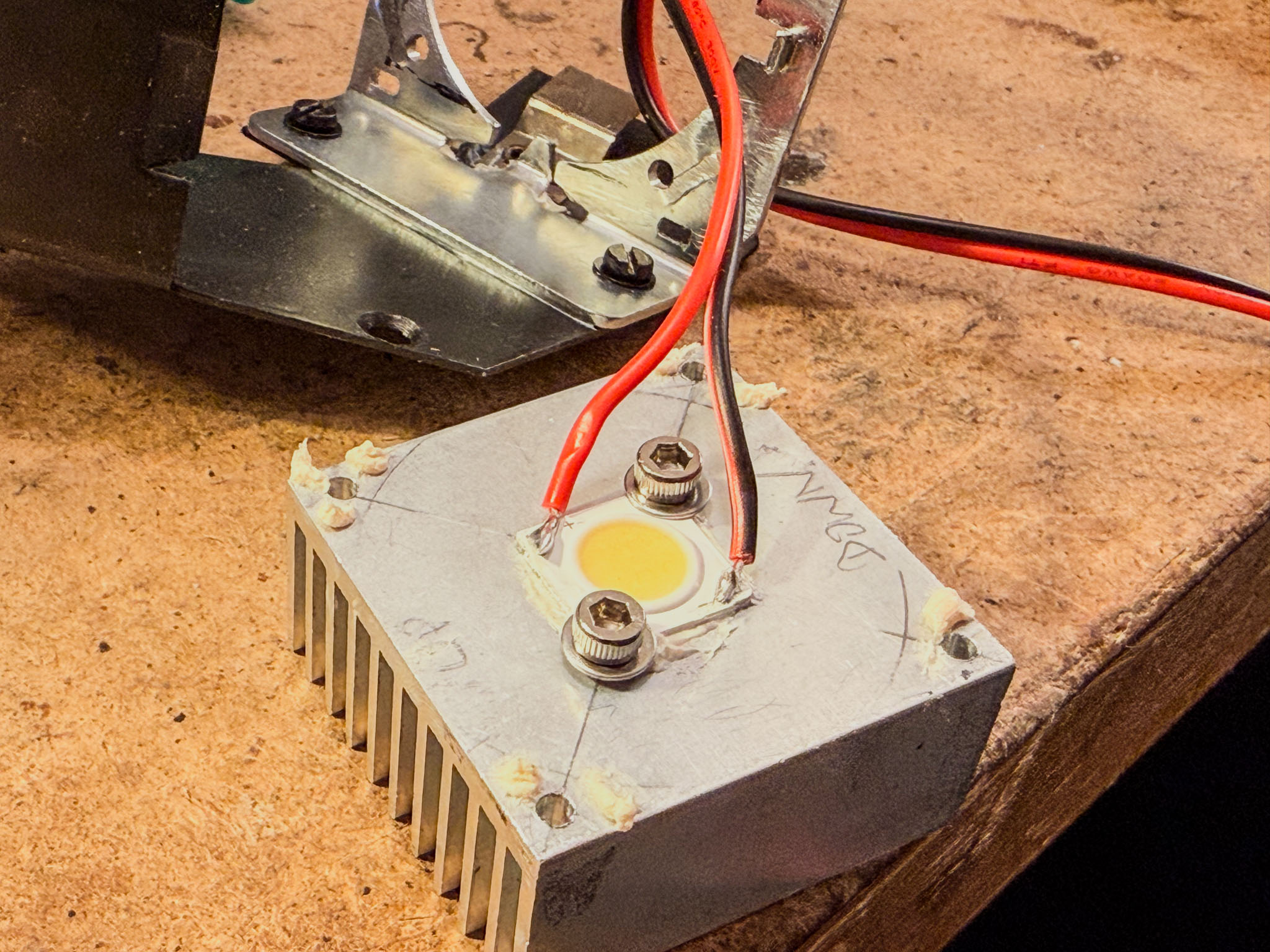
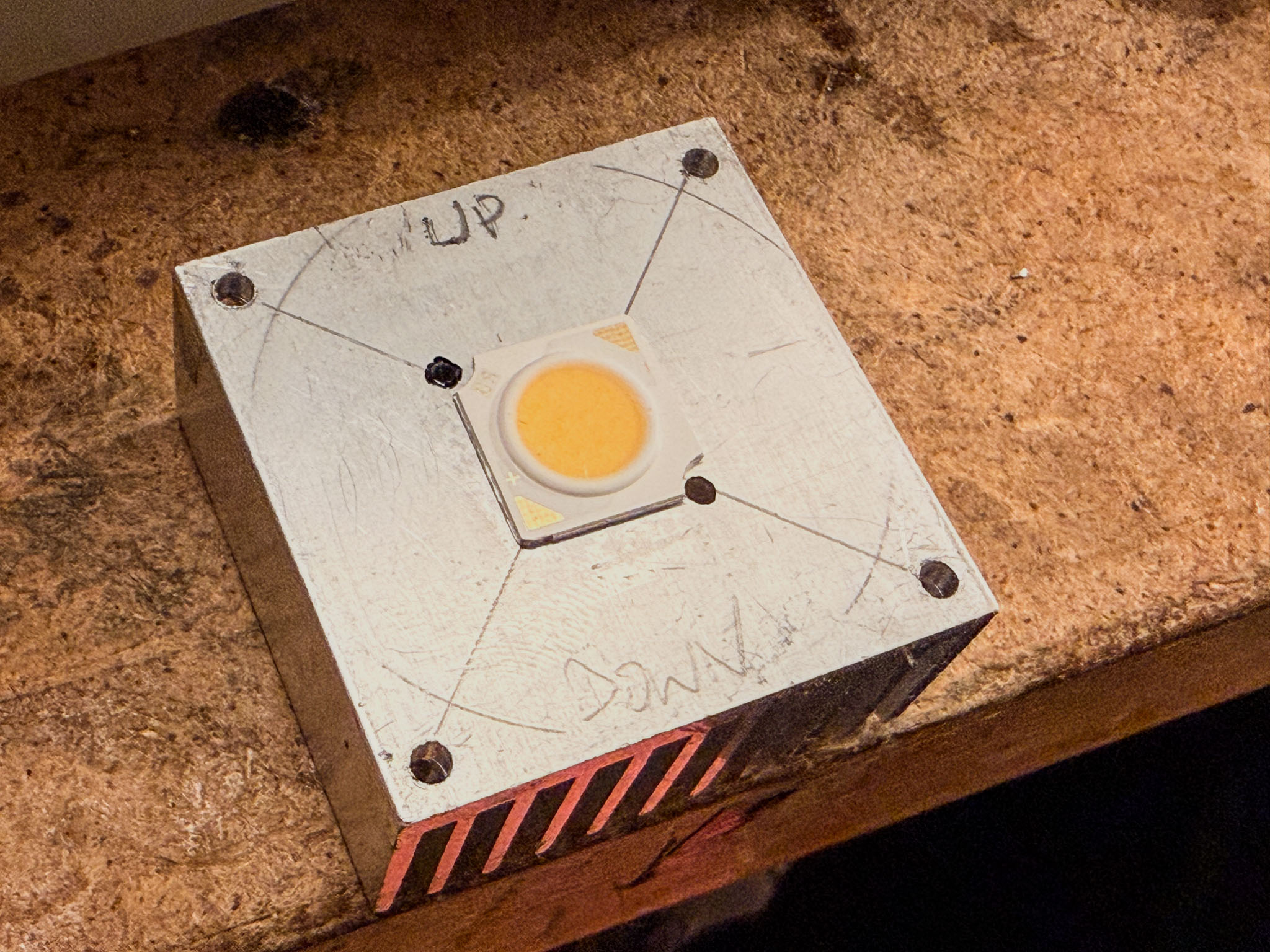 Position the LED in the center (if necessary, check centering from the front through the lens mount!) and drill two smaller holes so the LED can be screwed down securely. I have moved away from permanently gluing it, though that works too.
 Thermal paste (PC accessory) and two screws with washers ensure safe heat transfer.
The lamp holder is also mounted with thermal paste. This way, even the 5 W LED works safely without active cooling.
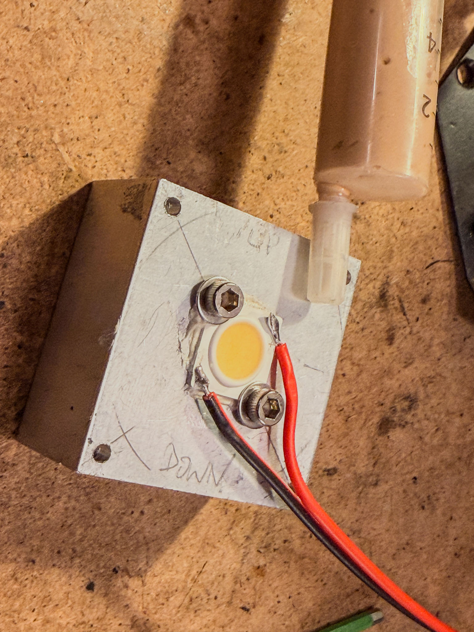
 Before screwing everything together, solder the supply wires to the LED. Mind the polarity and, if necessary, turn the soldering iron up a little, because the assembly is cooled very well here. Or just solder the wires before screwing it down... :)
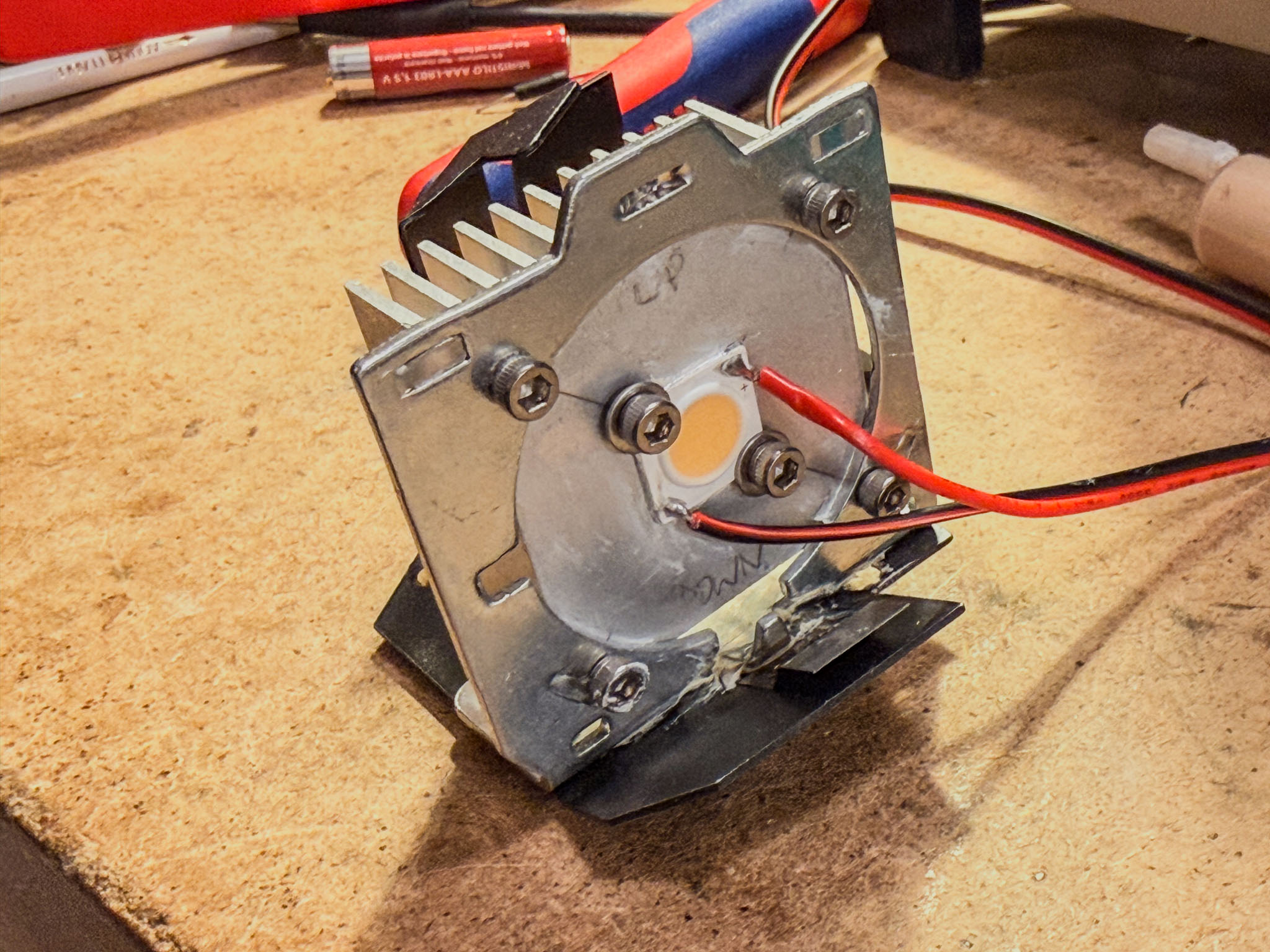 Done!
Done!
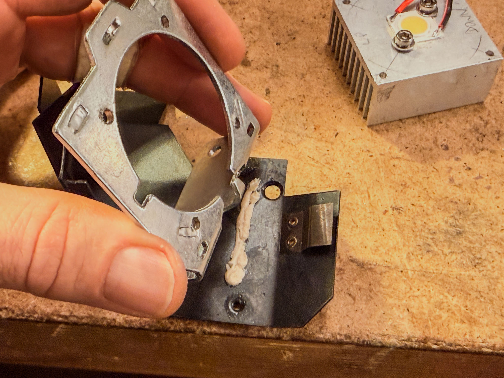
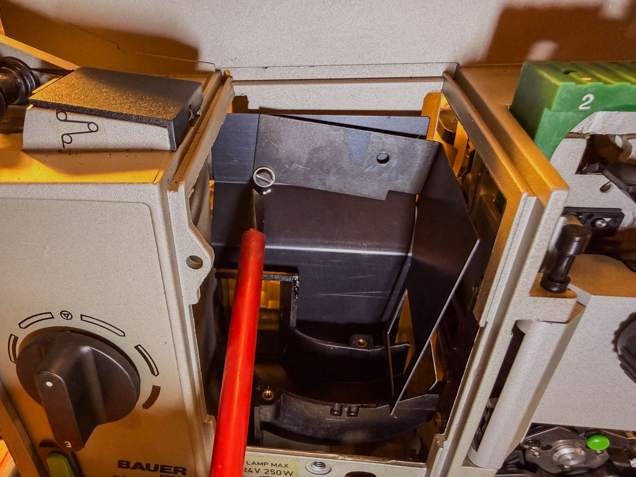 To attach the PTFE diffuser, loosen the front mask plate in the lamp house.
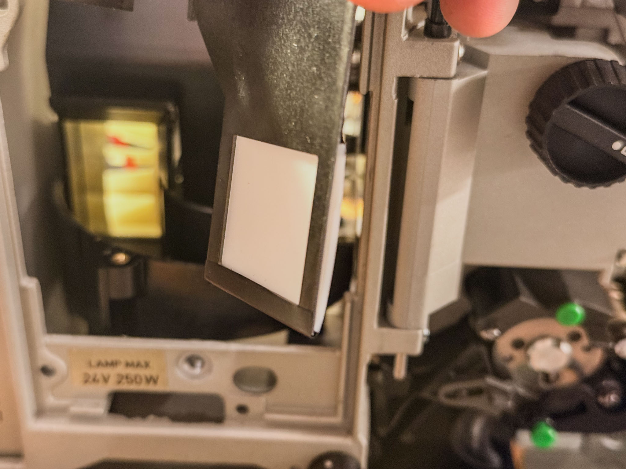 Simply attaching it with a little insulating tape is enough; PTFE is really difficult to glue permanently...
Now the lamp assembly can be fastened back into the lamp house together with the bottom plate.
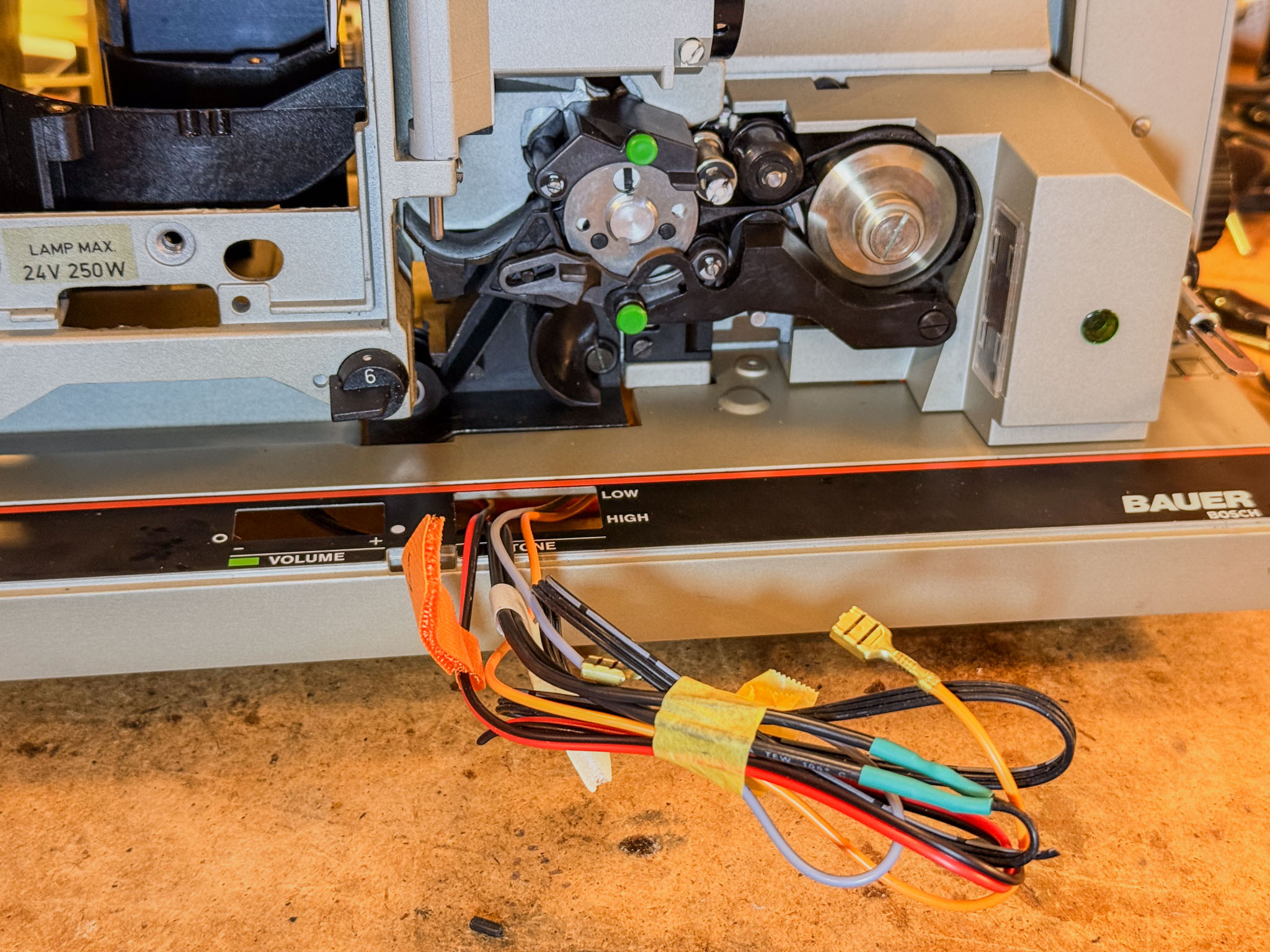
A very practical feature of the P8 is that it already has its own film-end sensor. Normally, this disconnects the projector completely from mains power (somewhat abruptly).
To continue using it, follow the two black cables (routed in a sleeve) that, viewed from the operating side, run from the lower center toward the mains socket.
 Wiggle the cable shoes loose with flat-nose pliers (if present), then clip them off.
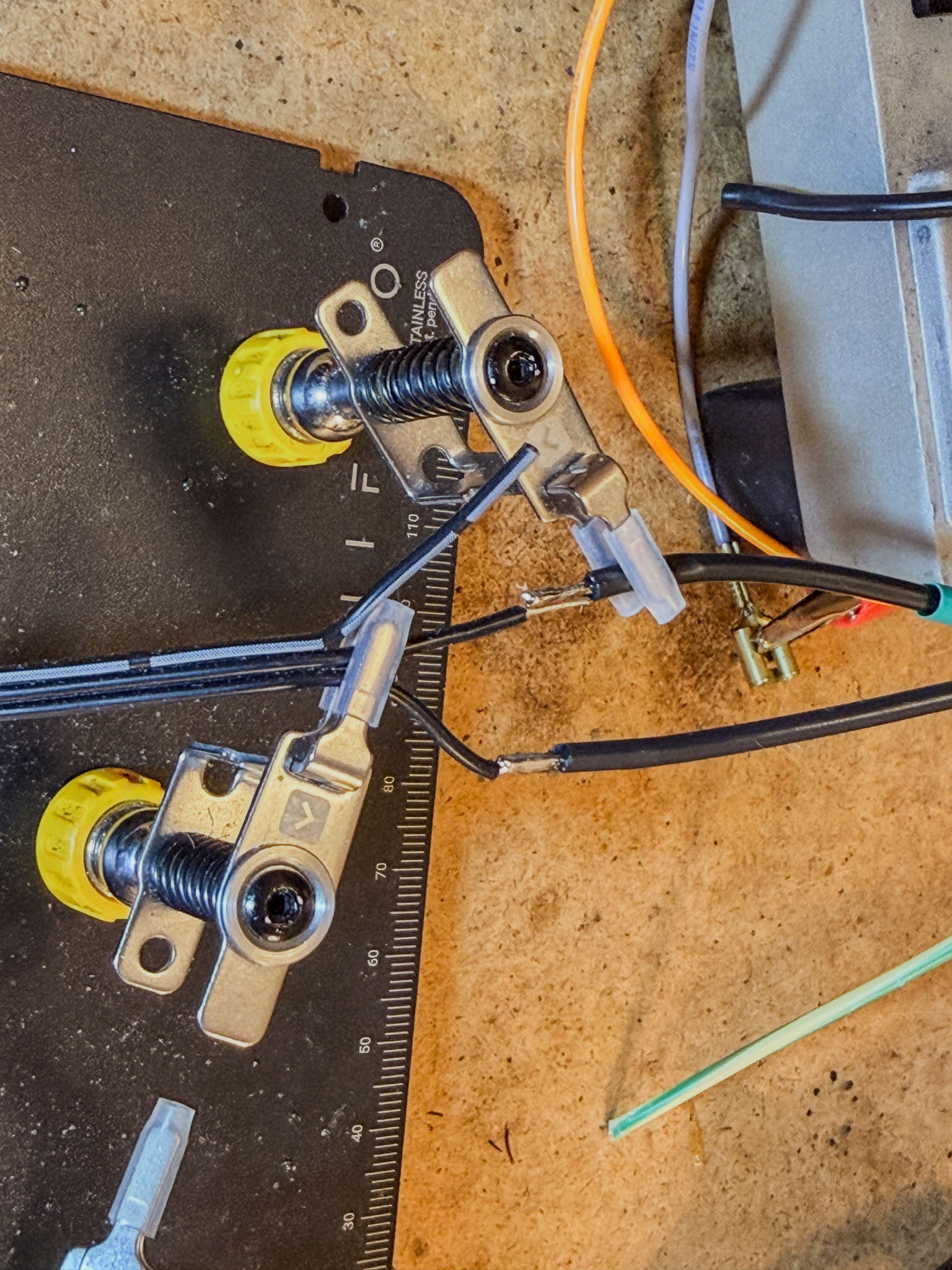 To connect the film-end sensor (coming from the right) to the controller board (three-wire cable going off to the left), it must be connected to ground (GND) and to the middle wire of the "Film End" terminal.
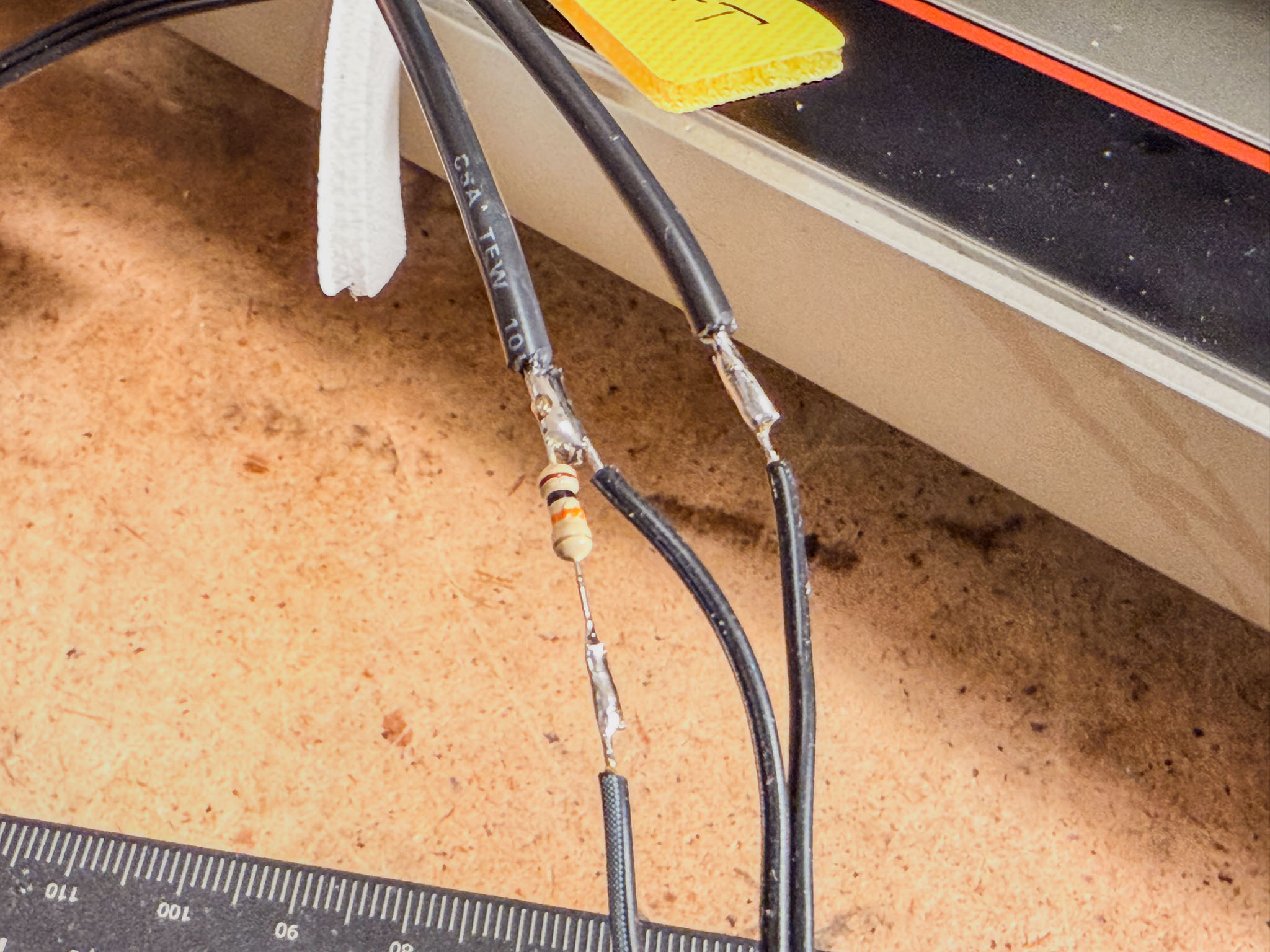 It is best to solder a resistor between the middle wire and "+" as a pull-up (any value between 4k7 and 47k ohms is fine here; this one is 10k).
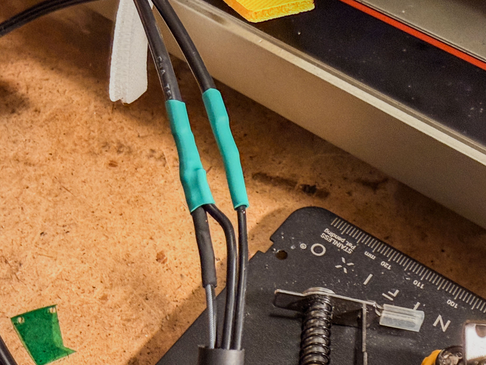 Heat-shrink tubing or insulating tape protects the solder joints from accidental contacts.
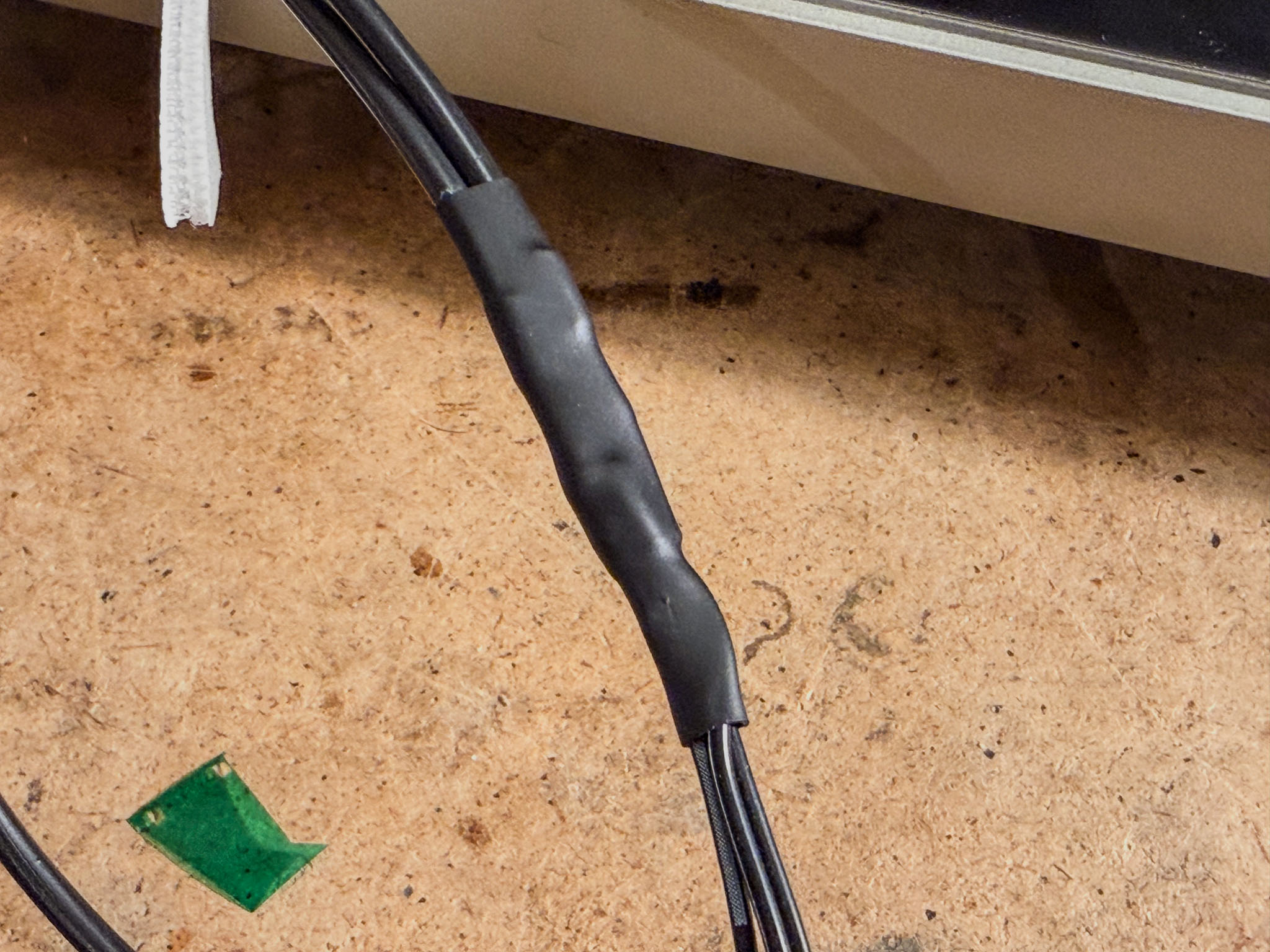 Shrunk together as a whole, it also looks nice and tidy. :)
The switching power supply is mounted in place of the old transformer. For the second screw, I drilled a hole into the former mounting plate of the voltage selector:
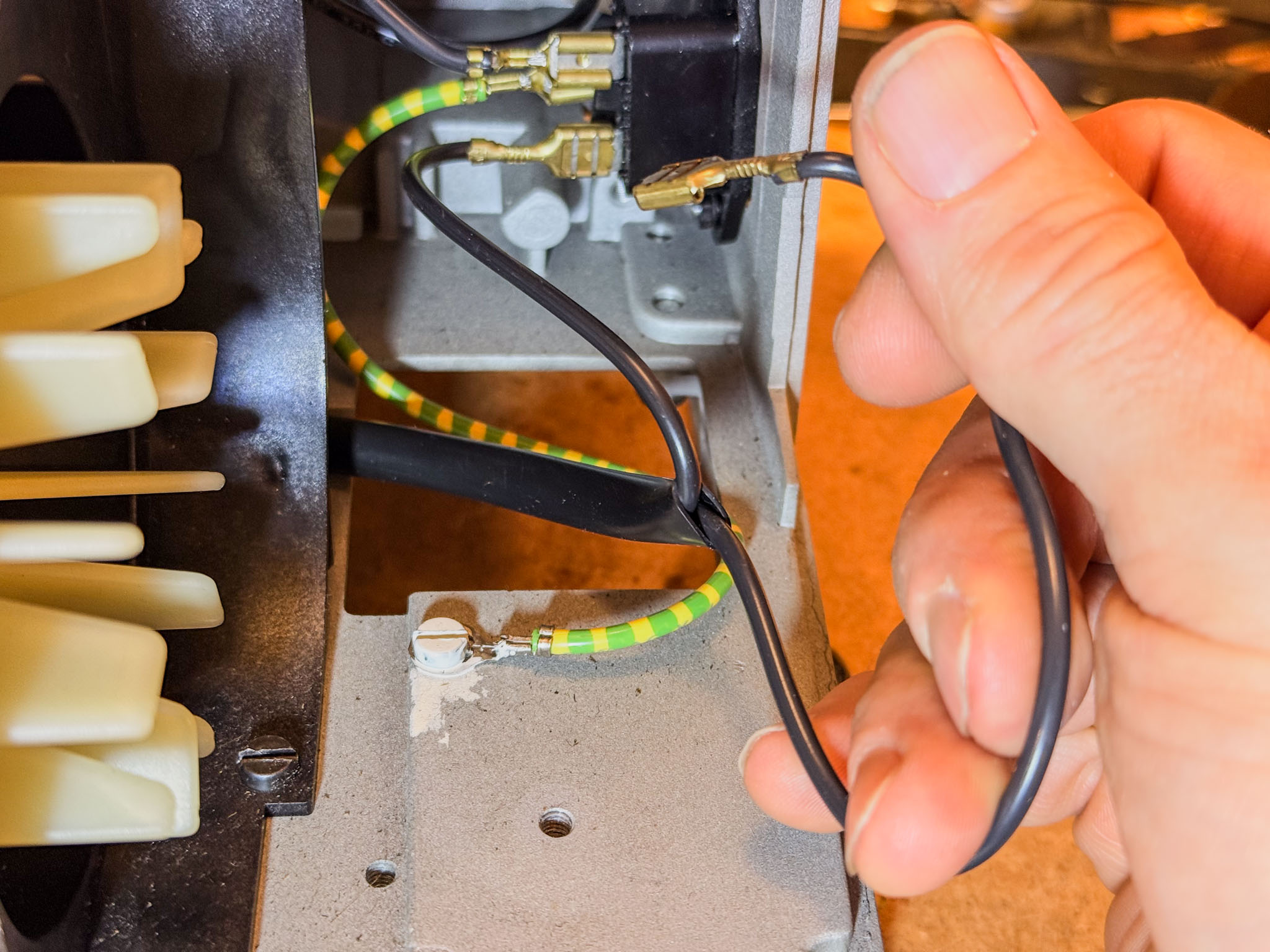
Now is a good time to wire the power connection. First, run an additional protective earth wire (usually green-yellow) from the screw in the bottom plate or from the mains socket to the Mean Well power supply, and screw it down securely.
Then connect the two black wires from the IEC power inlet to "L" and "N" on the switching power supply.
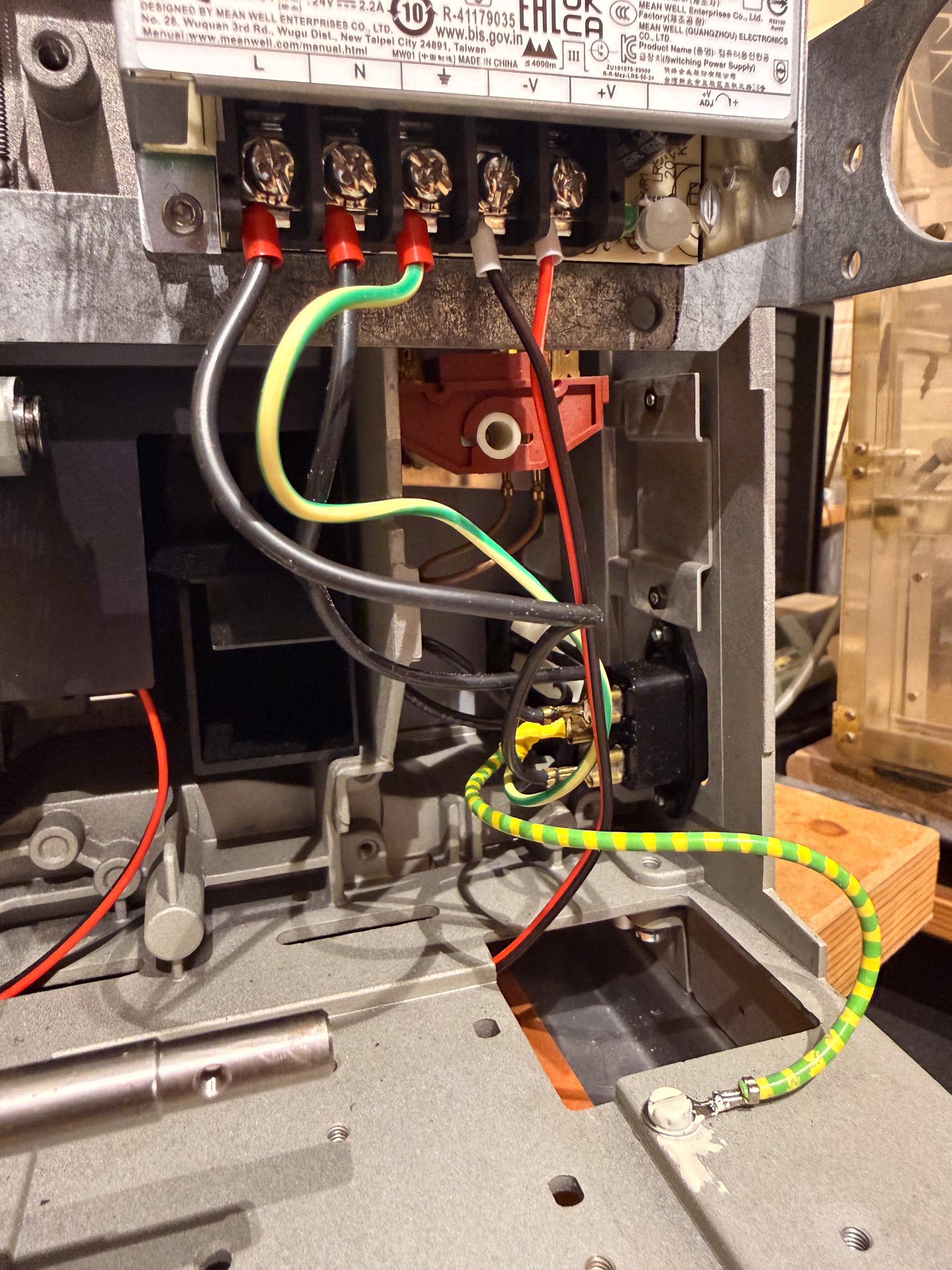 If you have a later-series P8 with a green toggle switch below the main control switch, it is worth keeping it wired into the mains line. Switching power supplies sometimes tend to whine when they have no load.
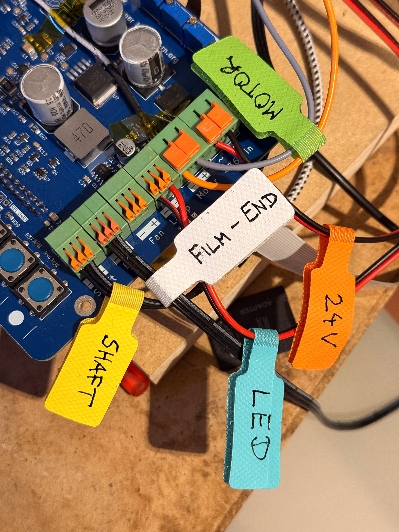
All connection cables can now be routed forward through the bottom tray (label them well if needed!).
Here is a connection table:
| Terminal on controller board | Projector side |
|---|---|
| Shaft - (GND) | - on the motor shaft sensor |
| Shaft ^ (Input) | ^ on the motor shaft sensor |
| Shaft + (Vcc) | + on the motor shaft sensor |
| End - (GND) | black wire from the film-end switch |
| End ^ (Input) | black wire from the film-end switch |
| End + (Vcc) | pull-up resistor (see above) |
| Fan - | unused |
| Fan + | unused |
| Lamp - | LED - |
| Lamp + | LED + |
| Motor - | orange wire from the motor |
| Motor + | gray wire from the motor |
| <36V in (polarity does not matter) | +V switching power supply |
| <36V in (polarity does not matter) | -V switching power supply |
I simply routed the cable bundle out through one of the potentiometer cutouts:
With little labels attached, it is much harder to get things mixed up: