Synchronized Gear Extruder
- Synchronized Gear and Extruder
- Sync Feedback Buffer type Sensors
- AutoTuner Settings
- FlowGuard Clog/Tangle detection
- How-to: Enabling telemetry logs
Happy Hare allows for syncing gear motor with the extruder stepper during printing. This added functionality enhances the filament pulling torque, potentially alleviating friction and under extrusion-related problems. It is crucial, however, to maintain precise rotational distances for both the primary extruder stepper and the gear stepper A mismatch in filament transfer speeds between these components can lead to undue stress and make synchronized printing worse and un-synced. It can also lead to filament grinding or printing artifacts.
You really have three choices:
- Print without synchronizing to the extruder - this is only possible on type-A MMU's where the MMU can release it's grip on the filament
- Carefully calibrate the rotational distance of the MMU gear stepper and print without feedback
- Approximate the rotational distance and use a sync-feedback "buffer" sensor to automate the synchronization for you
If choosing option 3 (and enabling sync-feedback) then Happy Hare has a lot more features which include:
- AutoTuner - the controller for determining how to match the extruder rotation distance.
- FlowGuard - a clog and tangle detection system.


 Synchronized Gear and Extruder
Synchronization during printing is controlled by sync_to_extruder in mmu_parameters.cfg. When set to 1—or when required by certain MMU designs such as Type‑B—the MMU will grip the filament after a tool change and the gear motor will synchronize with the extruder for all extrusion and retraction moves. If the MMU design supports it, this synchronization can also be selectively enabled for tip‑forming and purging operations.
mmu_parameters.cfg parameters:
# Synchronized gear/extruder movement ----------------------------------------------------------------------------------
#
# This controls whether the extruder and gear steppers are synchronized during printing operations
# If you normally run with maxed out gear stepper current consider reducing it with 'sync_gear_current'
# If equipped with TMC drivers the current of the gear and extruder motors can be controlled to optimize performance.
# This can be useful to control gear stepper temperature when printing with synchronized motor
#
sync_to_extruder: 0                     # Gear motor is synchronized to extruder during print
sync_gear_current: 50                   # % of gear_stepper current (10%-100%) to use when syncing with extruder during print
sync_form_tip: 0                        # Synchronize during standalone tip formation (initial part of unload)
sync_purge: 0 # Synchronize during standalone purging (last part of load)When sync options are enabled, the gear stepper will automatically coordinate and follow the extruder stepper. Any MMU operation that necessitates exclusive gear stepper movement (like buzzing the gear stepper to verify filament engagement), will automatically disengage the sync. Generally, you don't need to manually manage the coordination / discoordination of the gear stepper — Happy Hare handles these actions for you.
In type-A MMU designs (with a servo) if the printer enters an MMU_PAUSE state (due to a filament jam or runout, for example), synchronization may be automatically disengaged and the servo lifted. Upon resuming a print, synchronization will automatically resume. If you wish to enable it whilst operating the MMU during a pause, you can do so by using the MMU_SYNC_GEAR_MOTOR command.
The MMU_SYNC_GEAR_MOTOR SYNC={0|1} command functions as follows:
- Defaults to
sync=1 - If
sync=1it triggers the servo and executes the synchronization - If
sync=0it disengages sync and lifts the servo
Note: You can still control the gear stepper motor separately with the MMU_TEST_MOVE or MMU_TEST_HOMING_MOVE commands.
Warning
If you run the gear stepper synchronized for long prints you might find it can become very hot. You might want to consider using sync_gear_current to reduce the run_current used while synced during print to keep the temperature down. Afterall you probably don't need full power while printing. The current will be restored for loading and unloading operations.
During extended periods of synchronised printing without intervening tool changes, the alignment between the extruder and gear steppers can gradually drift. Even with precise calibration, factors such as under extrusion during purging, printing at high speed near upper flow limits, friction and drag along the filament path and the inertia of heavy spools can conspire to cause slippage in either the extruder or more commonly—the downstream gear stepper. Over time, this mismatch accumulates and can lead to print artefacts due to missed steps or suboptimal extrusion rates. Although not always apparent on well tuned systems, it is a legitimate and demonstrable issue. Fortunately Happy Hare can actively compensate for this behaviour by maintaining a balanced state through sensor based feedback mechanisms that counteract the buildup of tension or compression within the filament path. This is handled and managed by the Happy Hare AutoTune facility.
Happy Hare currently supports four different types of sync-feedback sensors:
- Tension Only (TO): Single switch sensor activated by tension in the filament (buffer shortened).
- Compression Only (CO): Single switch sensor activated by filament compression (buffer extended).
- Dual (D): Two switch sensor providing independent tension and compression signals and defined neutral band.
- Proportional (P): Analog (ADC based) sensor reporting continuous position data, including degrees of tension, compression, neutrality.
The Belay project by Annex Engineering is a good example of Type-TO. It sits somewhere in the bowden path between the MMU and extruder and provides a spring loaded "gap" in the PTFE tube and triggers when the filament starts to come under tension (the sensor shuttle moves towards the print head).
Many MMU projects already incorporate Type-D dual-switch sync-feedback sensor options. For example: QuattroSync from QuattroBox, TurtleNeck from BoxTurtle, and EMUSync from EMU – Expandable Multi-material Unit projects. Most of these sensor options currently rely on micro-switch mechanisms although the EMU project has a proportional sensor under development using the PFS Sensor module.
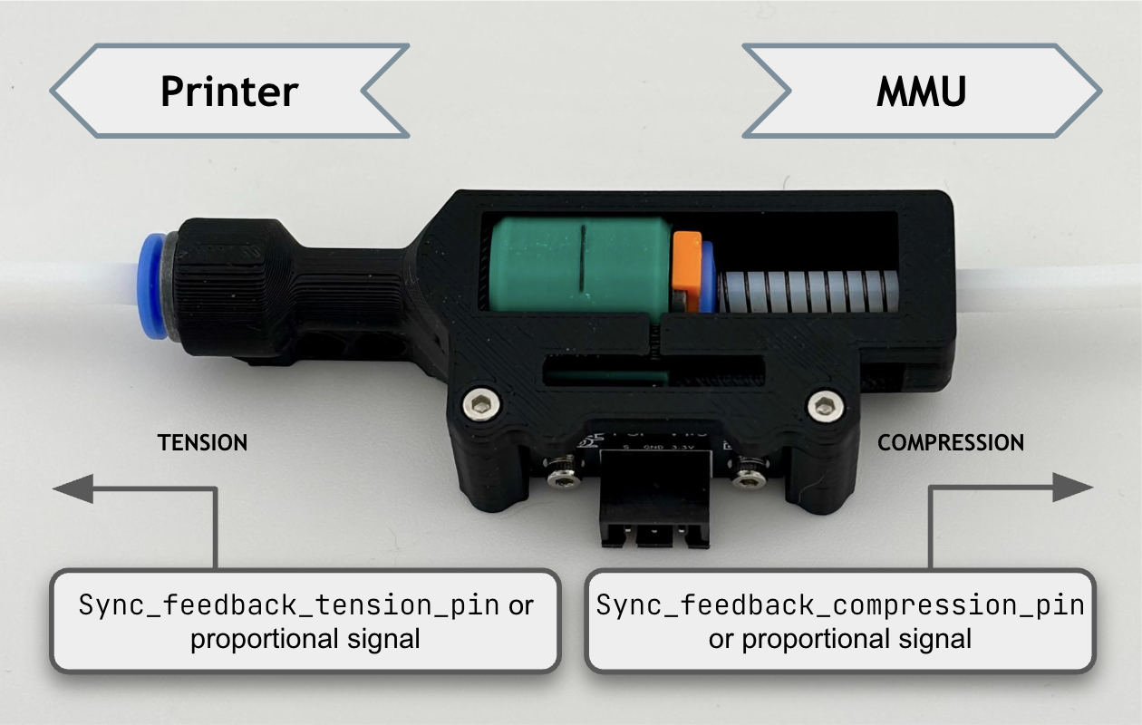
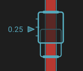
Pay attention to switch orientation - filament is under TENSION when the buffer mechanism is squeezed, and filament is under COMPRESSION when the buffer mechanism is expanded. E.g. look at this design:
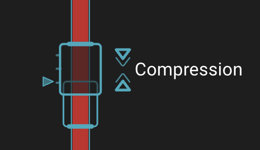
Extreme tension or compression is indicated in the Mainsail/Fluidd UI with additional annotation:
This section below contains the hardware setup instructions for a micro-switch based sync-feedback sensor. If you are using such a sensor, expand for more details.

Simply specify the single or dual GPIO switch pins in the [mmu_sensors] portion of mmu_hardware.cfg. If the micro-switch is not fitted just leave blank (no need to delete or comment out parameters with Happy Hare). Use the MMU_SENSORS command whilst manually trigging to ensure the correct orientation - Remember that filament tension will usually occur with the buffer squeezed together. Make sure you have the correct pins defined.
[mmu_sensors]
sync_feedback_tension_pin:                  # Micro-switch that triggers when the buffer is squeezed
sync_feedback_compression_pin:              # Micro-switch that triggers when the buffer is expanded
Initial configuration for micro-switch based sync-feedback sensors such as Belay, QuattroSync, TurtleNeck, and EMUSync.
Sync-feedback can be disabled even if the hardware has already been configure by changing the sync_feedback_enable parameter (during print you can use MMU_TEST_CONFIG sync_feedback_enable=[0|1] to dynamically alter its state).
The current state of sync-feedback will be shown in MMU_STATUS and MMU_SYNC_FEEDBACK commands, but you can also display the raw state of the sensor micro-switches with the MMU_SENSORS command:
> MMU_SENSORS
sync_feedback_tension_switch: open
sync_feedback_compression_switch: TRIGGERED
For the ultimate Gucci experience, fine resolution and precise, dynamic control — Proportional Feedback Sensors are the way to go if you don't already have a feedback sensor fitted.
Proportional sync-feedback sensors incorporate linear Hall Effect sensors (or similar) to provide analog positional data, allowing Happy Hare to continuously adjust and fine tune gear stepper Rotational Distance (RD) and if fitted with a compression spring—maintain positive compression on the filament to further unburden / unload the Bowden and extruder. Unlike micro-switch based sensors, proportional sensors require an Analog-to-Digital (ADC) capable GPIO pin (often used for thermistors) rather than the more ubiquitous endstop port. Please verify you have a spare GPIO of the correct type as they won’t work otherwise. Happy Hare normalises and represents data from proportional sensors using a scale of -1 to 1 with -1 indicating full tension, 1 full compression and 0 as the midpoint (neutral). See Calibration.
Happy Hare's analog sensor support was developed and tested using two of the more commonly available proportional options: the standalone FPS board from OpenAMS Project, and PFS Sensor with ADC GPIO's fitted with and without pull-up resistors. However it is designed to work with all analog sensors - let us know if it doesn't!
Because proportional sensors allow very precise control without significant variation, the normalised value is also shown in the Mainsail / Fluidd UI:
This section below contains the hardware setup instructions for a proportional analog sync-feedback sensor. If you are using such a sensor, expand for more details.
In the [mmu_sensors] portion of mmu_hardware.cfg specify the analog pin connected to the sensor. Leave the other settings as default for now because they will be determined when you perform the one-time calibration step later.
Set the ADC GPIO pin the proportional sync-feedback sensor is plugged into. Other settings will be updated and set after its calibrated.
[mmu_sensors]
sync_feedback_analog_pin: <your GPIO>           # The ADC pin where the proportional filament pressure sensor is installed
sync_feedback_analog_max_compression: 1         # Raw sensor reading at max filament compression (buffer squeezed)
sync_feedback_analog_max_tension: 0             # Raw sensor reading at max filament tension (buffer expanded)
sync_feedback_analog_neutral_point: 0.50        # Biasing of neutral point (sensor value 0). Normally close to 0.5
NOTE Proportional Sync-Feedback sensors must be plugged into an ADC capable GPIO port to function properly.
Also if the above block isn't already defined under the[mmu_sensors]section inmmu_hardware.cfg, manually add it to your configuration.
Once you have set the sync_feedback_analog_pin: and restarted Klipper / Kalico, you can use the MMU_QUERY_PSENSOR command to verify positional data is being received from the sensor. When the sensor is configured correctly and plugged into a valid ADC GPIO port, MMU_QUERY_PSENSOR will return raw (0 to 1) and normalised (-1 to 1) positional sensor values. Check the raw value changes when you move the sensor shuttle and rerun the command before continuing.
In this example, when the shuttle is held against each extreme, the sensor has returned raw values of 0.004 and 0.99 which is ideal and close to the sensors full ADC range.
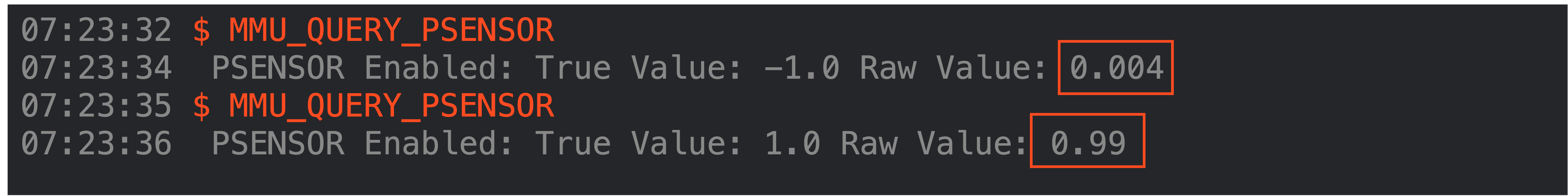
If your raw values never approach this (e.g. close to 0 or 1), verify the ADC GPIO is configured correctly and the pin isn’t jumpered or configured as a stepper diag input.
This is a necessary one-time operation to determine the ADC limits for your analog sensor and correct settings for sync_feedback_analog_max_compression, sync_feedback_analog_max_tension and sync_feedback_analog_neutral_point parameters.
MMU_CALIBRATE_PSENSOR can now be used to automatically determine the full range of sensor motion and required configuration values for the sensor.
Before running MMU_CALIBRATE_PSENSOR, ensure filament is loaded. The calibration routine will advance / retract the gear stepper in 2mm increments in both directions until the extremes are reached and sensor readings stop changing. If repeated calibrations produce significantly different results and recommendations, you may need to override and increase the maximum distanced probed e.g. MMU_CALIBRATE_PSENSOR MOVE=<distance in mm> By default, this distance is based on sync_feedback_buffer_maxrange defined in mmu_parameters.cfg.
Depending on the orientation of the sensors magnet or proportional feedback sensor design, reported values for compression and tension may be reversed or differ from the example shown below. For best fidelity, raw ADC values returned for sensor limits should ideally be as close to 0 and 1 as possible.
> MMU_CALIBRATE_PSENSOR
Modifying MMU stepper_mmu_gear run current to 30% (0.36A) while calibrating sync_feedback psensor
Run Current: 0.37A Hold Current: 0.21A
Finding compression limit stepping up to 14.00mm
Seeking ... ADC compressed limit: 0.2311
Seeking ... ADC compressed limit: 0.6419
Seeking ... ADC compressed limit: 0.9831
Seeking ... ADC compressed limit: 0.9839
Backing off compressed limit
Finding tension limit stepping up to 14.00mm
Seeking ... ADC tension limit: 0.0623
Seeking ... ADC tension limit: 0.0078
Seeking ... ADC tension limit: 0.0065
Seeking ... ADC tension limit: 0.0064
Backing off tension limit
Restoring MMU stepper_mmu_gear run current to 100% (1.20A)
Run Current: 1.20A Hold Current: 0.22A
Calibration Results:
As wired, recommended settings (in mmu_hardware.cfg) are:
[mmu_sensors]
sync_feedback_analog_max_compression: 0.9839
sync_feedback_analog_max_tension:     0.0064
sync_feedback_analog_neutral_point:   0.4952
After updating, don't forget to restart klipper!
Manually enter and update these details in mmu_parameters.cfg and restart Klipper / Kalico.
The Sync-Feedback "buffer" sensor physical dimensions should be entered for all sensor types in mmu_parameters.cfg. It is used in many circumstances to validate movement, optimize autotuning, etc. Most popular designs will be similar to the default but ensure that maxrange is set to the total physical movement available in the buffer and range to the distance between max-compression and max-tension signals.
# Possible buffer setups, forth option for type where neutral is when both sensors are active:
#
#   <------maxrange------>       <------maxrange------>       <------maxrange------>       <------maxrange------>
#        <--range--->                  <----range----->       <----range----->                       <> range=0
#   |====================|       |====================|       |====================|       |====================|
#        ^          ^                  ^                                     ^                       ^^
#   compression   tension        compression-only                      tension-only
#
sync_feedback_buffer_range:                 # Travel in "buffer" between compression/tension or one sensor and end (see above)
sync_feedback_buffer_maxrange:              # Absolute maximum end-to-end travel (mm) provided by buffer (see above)
For type-P sensors, range is the distance over which the ADC value changes (and typically will be the same as maxrange)
#   <------maxrange------>
#      <----range---->
#   |====================|
#   ^                    ^
# compression        tension
#
sync_feedback_buffer_range:                 # Travel in "buffer" between compression/tension or one sensor and end (see above)
sync_feedback_buffer_maxrange: # Absolute maximum end-to-end travel (mm) provided by buffer (see above) AutoTune is the heart of the sync-feedback system in Happy Hare—it intelligently monitors filament tension, compression, and positional data whenever Happy Hare is configured with a sync feedback sensor and dynamically adjusts the gear stepper's rotational_distance (RD) for different sync-feedback sensors as follows:
-
CO and TO (Single-switch sensors: Tension or Compression): Adjusts and sets
RDbias on the sensor switch, backing off and oscillating between activated and deactivated states. - D (Dual-switch sensors): Oscillates between both switches in a bang-bang control pattern (This is slightly different to previous Happy Hare sync-feedback sensor logic).
- P (Proportional): Always attempts to maintain a neutral position based on positional data from the sensor.
By constantly measuring the extruder's RD, AutoTune is able to provide an automatic calibration value but also maintaining a reference for features like FlowGuard clog / tangle detection and for flowrate monitoring (flowrate monitoring requires a proportional sensor).
There are two flavors of algorithm depending on your sensor type with slightly different setup requirements:
-
Two-Level
- Used by switch based sensors (Type-CO, TO, & D).
- Available for proportional sensors but not recommended.
-
EKF (Extended Kalman Filter)
- Used by proportional (analog) sensors (Type-P).
This mode of operation continually switches the speed of the MMU gear stepper by a % greater or lower than the autotuner's estimation of the correct RD. Initially to ensure rapid correction of filament tension and to allow for seeking the correct RD even if the starting value is way off.
The algorithm uses: sync_feedback_speed_multiplier + sync_feedback_boost_multiplier delta.
After the autotuner locks in on a good estimation of RD, the clamping ranged is reduced to:
sync_feedback_speed_multiplier to slow the oscillation down.
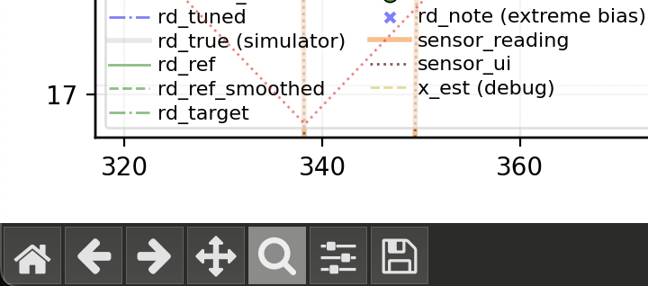
The autotuner will continue to seek for a more accurate RD resulting in a balanced oscillation. If you are interested in the internals, this is demonstrated in the flowing telemetry plot (you can even do this yourself).
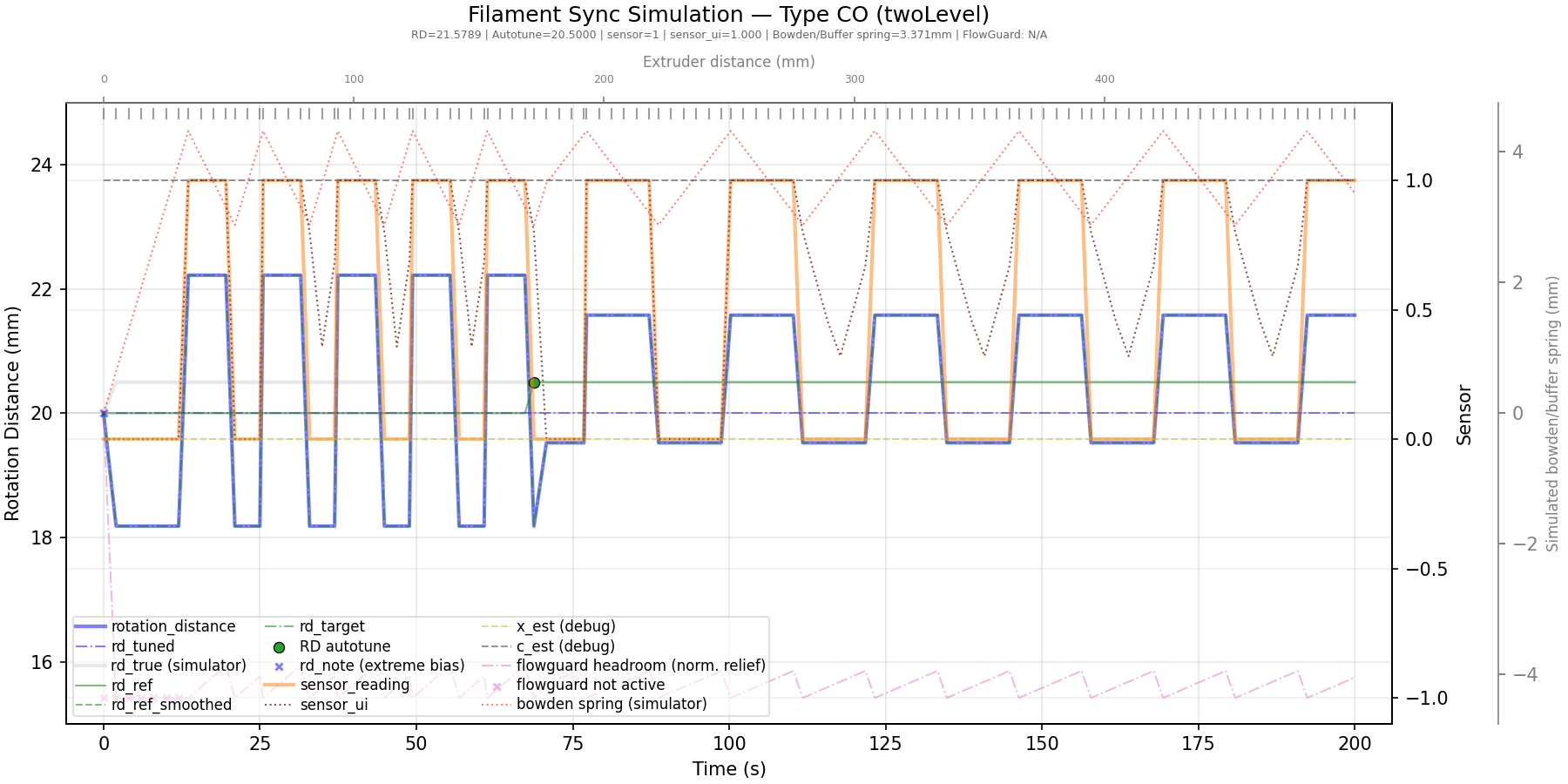
Explanation: The heavy blue line shows the gear’s rotation distance, while the orange line represents the Type‑CO sensor input. The AutoTuner begins with a gear RD value of 20, but the actual extruder value is closer to 20.5. This mismatch produces the wide, rapid oscillations visible at the start. As the AutoTuner converges on the correct RD, the oscillations shrink and the system stabilizes around the correct value.
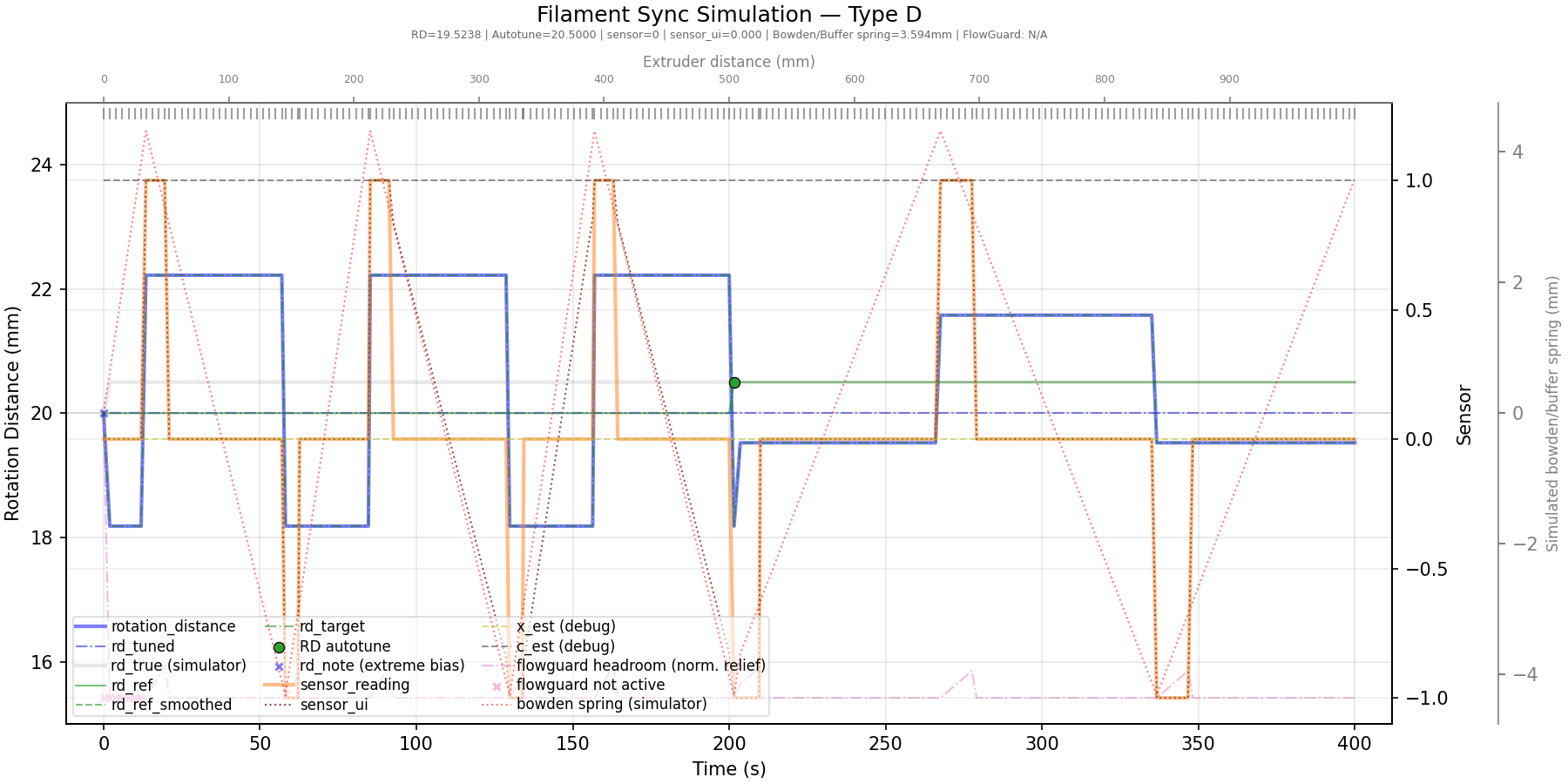 Similar plot for Type-D sensor.
The default values of the speed and boost multipliers are almost certainly good enough but now you know what adjusting them will do.
sync_feedback_speed_multiplier: 5       # % "twolevel" gear speed delta to keep filament neutral in buffer (recommend 5%)
sync_feedback_boost_multiplier: 3       # % "twolevel" extra gear speed boost for finding initial neutral position (recommend 3%)
Note
Unlike earlier Happy Hare Dual micro-switch logic, with Flowguard, all three micro switch based sensor types (TO, CO, and D) now operate by continuously oscillating between activated and deactivated states in a bang bang control pattern. Do not be alarmed, this is by design and expected behaviour. It allows for continuous seeking of the correct RD and is fundamental to the "two-level" logic. It in no way effects your print quality!
This mode of operation is available with analog Type-P sensors and is very accurate. The autotuner employs an adaptive, Extended Kalman Filter (EKF) to correlate sensor feedback data with extruder demands and motion, allowing it to continuously estimate the effective rotation_distance (RD) for the following gear stepper. The EKF models how tension, compression, and positional signals evolve in response to extruder movement and uses this information to infer RD and adjustments needed to keep the following gear stepper synchronised—either increasing to catch up or decreasing to avoid overshooting the extruder.
Happy Hare's EKF tuning was developed and tested using two of the more commonly available proportional options: the standalone FPS board from OpenAMS Project, and PFS Sensor with ADC GPIO's fitted with and without pull-up resistors.
If you are interested, a Kalman filter is "an algorithm for estimating and predicting the state of a system in the presence of uncertainty, such as measurement noise or unknown influences of external factors. The Kalman Filter is an essential tool in areas like object tracking". It is extremely applicable to motor synchronization in a 3D-printer context as can be seen by this, rather uneventful plot:
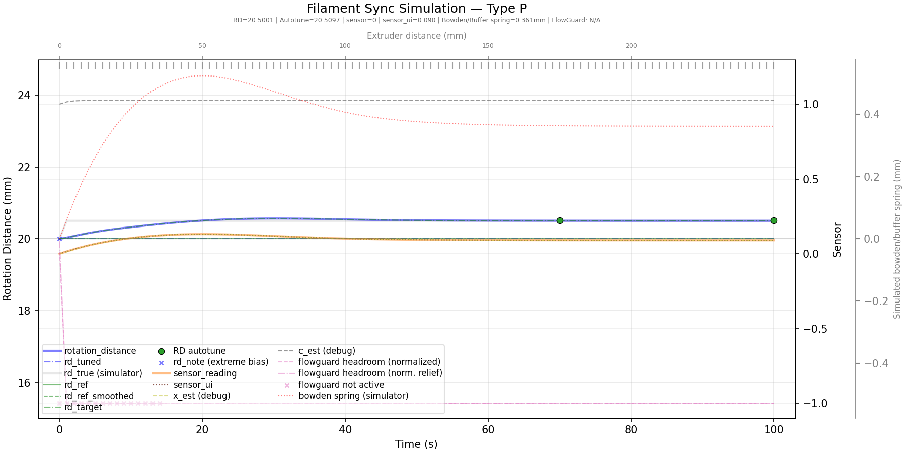
Explanation: Similar to the earlier Type‑CO plot, the gear stepper begins with an initial RD of 20 while the extruder’s actual value is 20.5. The blue trace shows how Happy Hare continuously adjusts the gear RD, rapidly converging on the correct AutoTune value. This approach is highly tolerant of noise and maintains near‑perfect synchronization even as the extruder’s behaviour shifts—for example, during infill‑related under‑extrusion.
There is one more setting you may want to adjust: the amount of extruder movement permitted before the AutoTuner runs. This applies to all sensor types. Regardless of this value, the AutoTuner will always trigger when a sensor reaches an extreme limit, ensuring maximum responsiveness to filament‑tension issues.
This setting specifies, in millimetres, how far the extruder moves between checks. The default of 5mm has proven to work well in practice. It should be larger than your maximum retraction distance, but not excessively large. Values below 5mm are generally unnecessary and may increase the likelihood of TTC (Timer Too Close) errors by creating unnecessary RPi load.
sync_feedback_extrude_threshold: 5 # Extruder movement (mm) for updates (keep small but set > retract distance)Dynamically control sync-feedback behaviour as below. Post filament load, Flowguard will automatically attempt to adjust filament tension and centre and / or move the sync-feedback sensor shuttle back from either extreme to prevent issues and triggering clogs / tangles when the print resumes. MMU_SYNC_FEEDBACK ADJUST_TENSION=1 is also called from the optional MMU_PURGE and BLOBIFIER macros post purging / blobbing.
Execute without arguments to display the current status.
> MMU_SYNC_FEEDBACK HELP=1

MMU_SYNC_FEEDBACK: Controls sync feedback and applies filament tension adjustments
└ HELP           = [1]   display help & options
└ ENABLE         = [1|0] enable/disable sync feedback control
└ ADJUST_TENSION = [1|0] apply correction to neutralize filament tension
└ AUTOTUNE       = [1|0] allow saving of autotuned rotation distance

> MMU_SYNC_FEEDBACK

Sync feedback feature with type-P (EKF mode) sensor is enabled (not currently active)
RD: Current:22.87, Autotune recommended:22.87, Default:22.86
Sync feedback state: tension (flowrate: 100.0%)
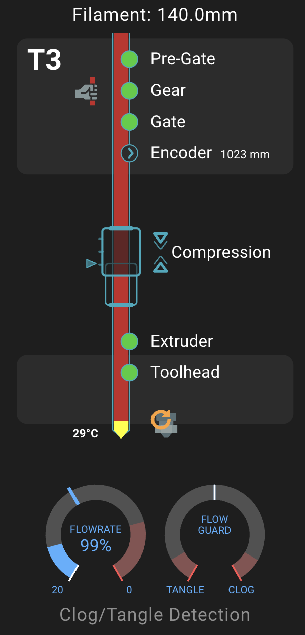
FlowGuard is Happy Hare's filament monitoring system. It is capable of detecting and handling filament runouts, extruder clogs, MMU spool tangles. In a nutshell, many sensors contribute to FlowGuard including:
- Pre-gate, post-gear, gate, extruder (entry),toolhead sensors and Encoder can all trigger Runouts.
- Sync-Feedback sensor and Encoder can detect and trigger Clogs.
- Sync-Feedback sensor and Encoder can detect and trigger Tangles.
FlowGuard intelligently monitors filament tension, compression, and positional data including enhanced detection of extruder clogs and MMU tangles. All Flowguard options are configured and managed in the same way, regardless of the type of sync-feedback sensor fitted. The active Flowguard state can be monitored and visualised in Mainsail and Fluidd using the Happy Hare dashboard extension.
Flowguard can be enabled | disabled in mmu_parameters.cfg with:
flowguard_enabled: 0 # 0 = Flowguard protection disabled, 1 = EnabledFlowguard clog / tangle detection can also be dynamically managed using the following command and arguments.
Execute MMU_FLOWGUARD without arguments to display the current status.
MMU_FLOWGUARD: Enable/disable FlowGuard (clog-tangle detection)
└ HELP           = [1]   display help & options
└ ENABLE         = [1|0] enable/disable FlowGuard clog/tangle detection

MMU_FLOWGUARD
FlowGuard monitoring feature is enabled (not currently active)
Dynamically control Happy Hare sync-feedback behaviour as below. Post filament load, Flowguard will automatically attempt to adjust filament tension and centre and / or move the sync-feedback sensor shuttle back from either extreme to prevent issues and triggering clogs / tangles when the print resumes. MMU_SYNC_FEEDBACK ADJUST_TENSION=1 is also called from the optional MMU_PURGE and BLOBIFIER macros post purging / blobbing.
Execute without arguments to display the current status.
This is the most important setting for FlowGuard and control how much movement is allowed without the sensor responding before triggering a clog or tangle as appropriate.
The relief parameter represents how much adjustment the AutoTune algorithm can apply to the filament and the distance the sync-feedback "buffer" shuttle should have moved in a perfect system. For type-P sensors this can be quite small because of how well AutoTune is able to maintain a neutral bias. For switch-based sensors, particularly type-D, you may need to increase this if you experience too many false triggers.
The biggest obstacle in tuning this parameter is understanding that the filament inside a bowden has a lot of "play". The play can be a result of using large ID bowden tube (e.g. 3mm ID), or a long bowden length - the filament tends to coil up inside the tube. This play must generally be ADDED to the range of movement in the sync-feedback buffer to determine the right trigger value. I recommend starting high and reducing until you experience false triggers and then increase about 20% from there. Alternatively you can learn to Interpret the Telemetry for precise setting or even watch the FlowGuard dial in Mainsail or Fluidd UI.
# The flowguard_max_relief is the amount of relief movement (effective mm change in filament length between MMU and extruder)
# that Happy Hare will wait until triggering a clog or runout. A smaller value is more sensitive to triggering. Since the
# relief movement is hightly dependent on filament "spring" in the bowden tube, filament friction, and
# 'sync_feedback_buffer_range', it is generally good to start high and then decrease if a more sensitive trigger is desired.
# Analog proportional (type P) sensors can generally have a much lower value. Increase if you have false triggers.
flowguard_max_relief: 40
Tip
When a FlowGuard clog / tangle is detected, the error message will display the parameter that caused the trigger. E.g.
MmuSyncFeedbackManager: FlowGuard detected a tangle.
Reason for trip: Tension stuck after 63mm motion and 8.3mm relief (triggering parameter: flowguard_max_relief)
If you feel this is a little trigger happy, you can increase the offending parameter. Don't forget that you
can even do this dynamically in-print using the MMU_TEST_CONFIG <parameter> command!
As explained in the above TIP, you can use the error message to tune max_relief and / or monitor the respective meters in the Mainsail / Fluidd UI's. However if you really want to optimize for early detection, your best option is to temporarily enable telemetry, then run the plot_sync_feedback.sh script and examine the plot to determine FlowGuard behaviour at various parts of your print.
Runout and Clog / Tangle detection is well documented on the Encoder Clog/Tangle/Runout EndlessSpool page. Unlike the sync-feedback flowguard implementation it is impossible to distinguish between a clog and a tangle with just an encoder. This isn't of practical importance because both require manual intervention. However, the encoder can also detect runouts and thus trigger EndlessSpool to enable uninterrupted printing.
The flowguard_encoder_max_motion setting configured here represents the maximum permitted extruder movement. This is the distance used when flowguard_encoder_mode: 1 (manually set distance). It is also the default until a calibrated value is determined and stored in mmu_vars.cfg for flowguard_encoder_mode: 2 (automatically set distance).
# Encoder runout/clog/tangle detection watches for movement over either a static or automatically adjusted distance - if
# no encoder movement is seen when the extruder moves this distance runout/ clog/tangle event will be generated. Allowing
# the distance to be adjusted automatically (mode=2) will generally allow for a quicker trigger but use a static length
# (mode=1, set encoder_max_motion) if you get false triggers (see flowguard guide on wiki for more details)
# Note that this feature cannot disinguish between clog or tangle.
flowguard_encoder_mode: 2 # 0 = Disable, 1 = Static length clog detection, 2 = Automatic length clog detection
# The encoder_max_motion is the absolute max permitted extruder movement without the encoder seeing movement when using
# status mode (mode=1). Smaller values are more sensitive but beware of going too small - slack and friction in the
# bowden may cause gaps in encoder movement. Increase if you have false triggers.
# Note that this value is overriden by any calibrated value stored in 'mmu_vars.cfg' if in automatic mode (mode=2).
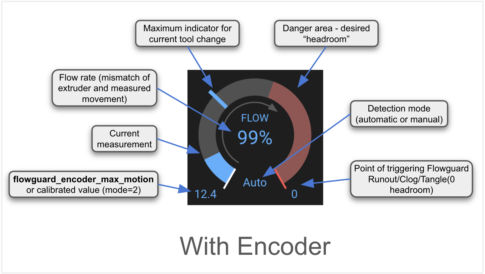
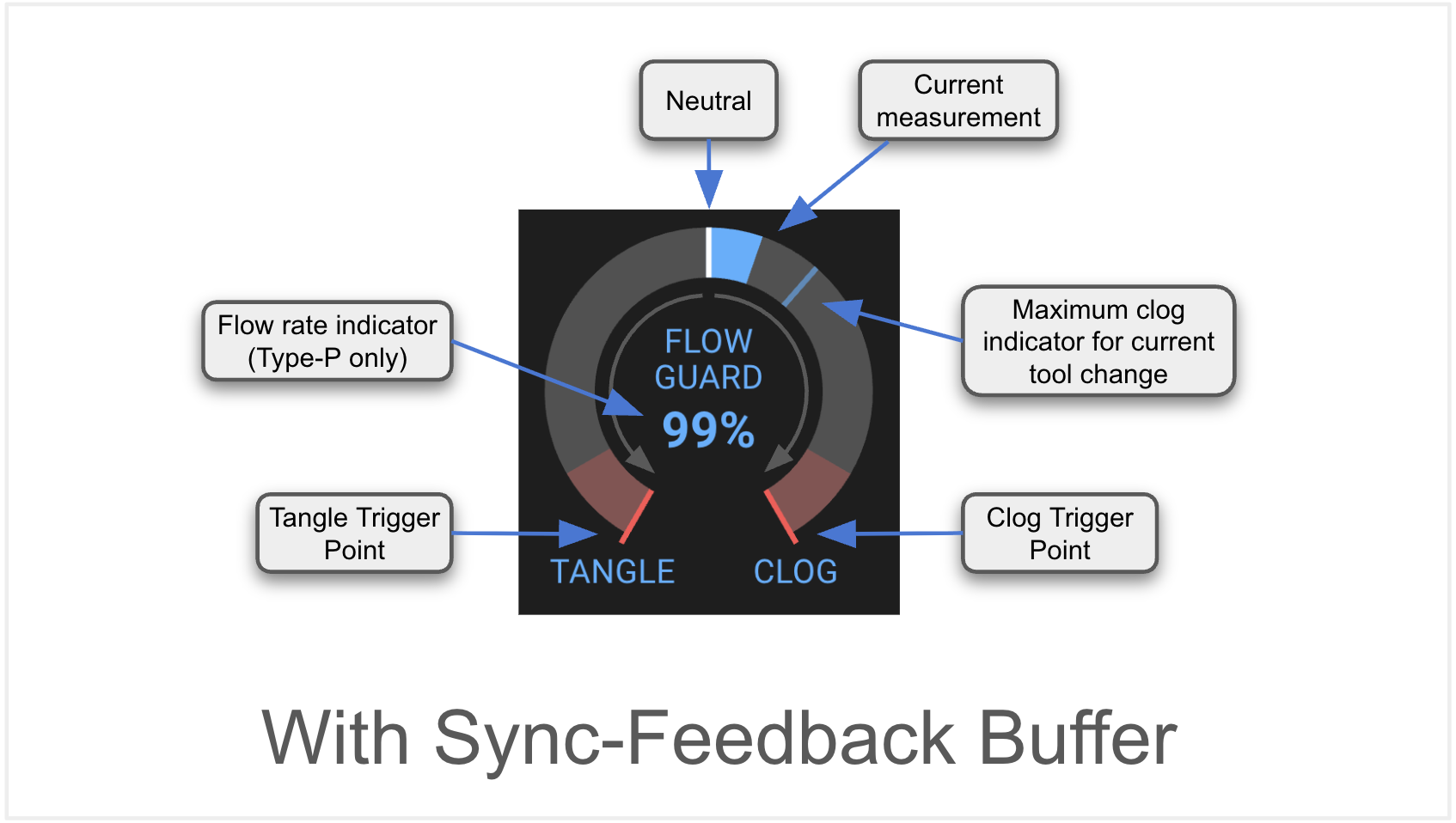
flowguard_encoder_max_motion: 20Two conditional forms of "FlowGuard Meters" are available in both Mainsail and Fuidd UI's. The first is the Runout / Clog / Tangle meter available when an encoder is fitted. The second when a sync-feedback "buffer" is fitted. It is entirely possible to have both! Capabilities explained below:
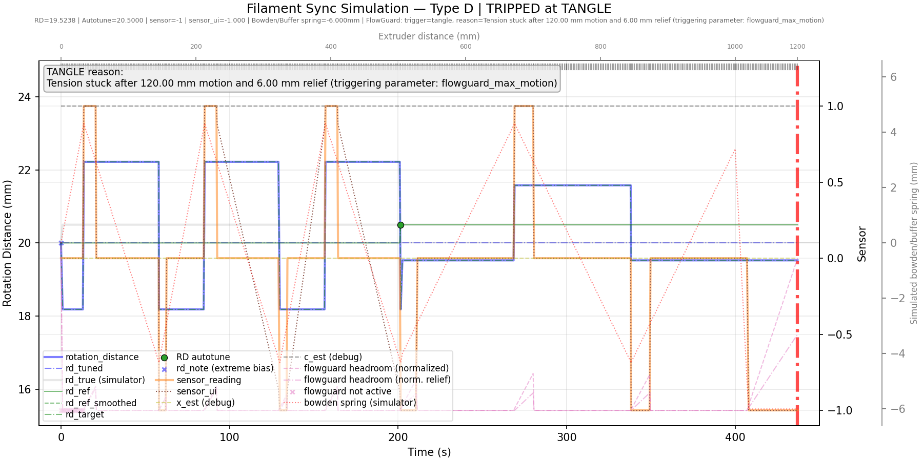
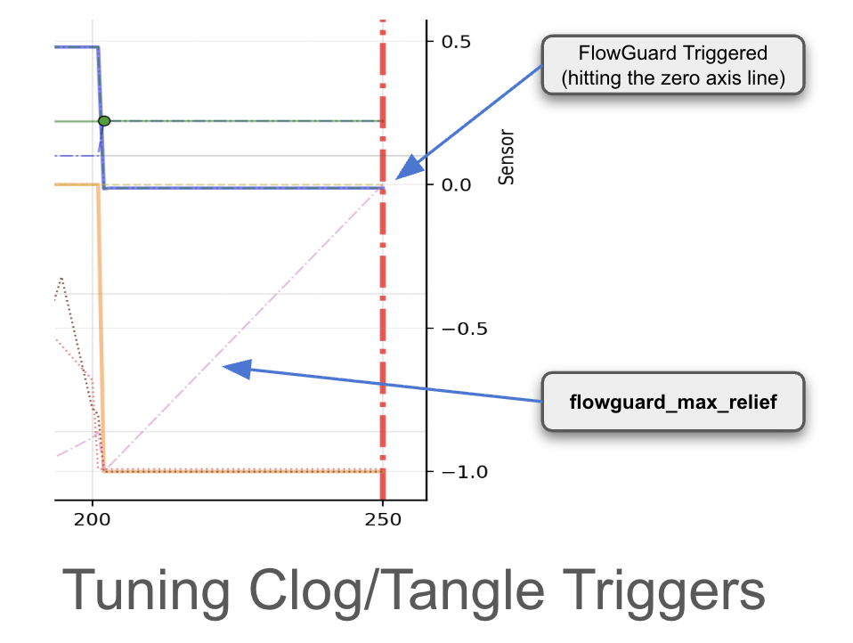
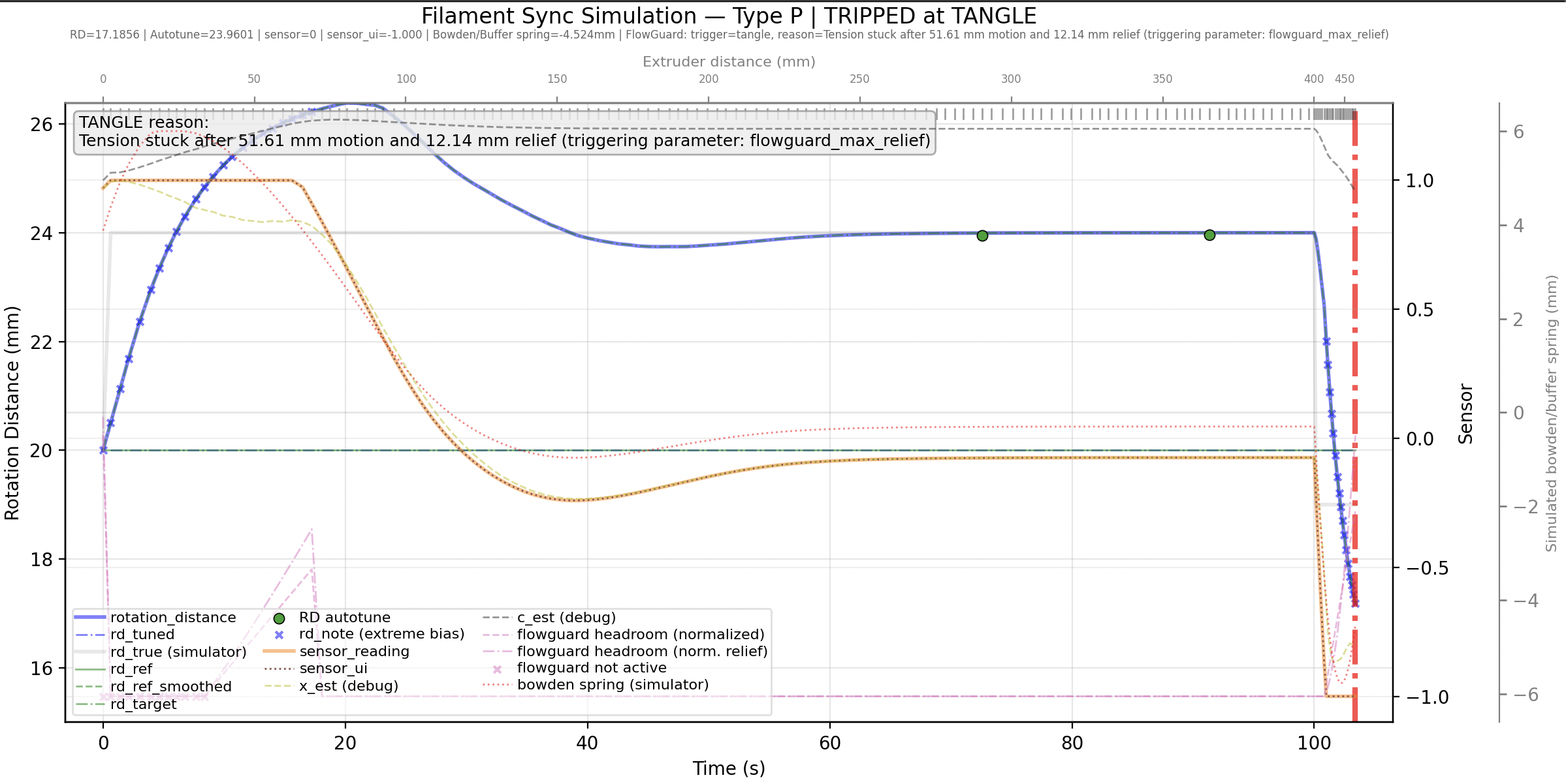
Once you’ve collected and plotted telemetry data, you can use it to diagnose and debug a tangle condition. This typically appears toward the end of the log, but remember that a separate log is maintained for every gate on the MMU, and each tool change is appended to it until the log is reset at the start of the next print. Locate the region of interest—this is much easier when using the interactive viewer described later.
The fine red “ramp” trace is the key signal to watch. The dash‑dotted _ . _ . line shows the rise toward the flowguard_max_relief threshold. Crossing the origin (“0”) axis marks the trigger point, highlighted by the heavy red vertical bar. Generally a false trigger is because of "spring" or filament coiling in the bowden that results in more that expected "relief" movement. Imagine a perfect system where there is NO PLAY in the filament in the bowden. Then the "relief" movement would be exactly the distance the sync-feedback sensor piston should move.
Other useful indicators include the green dots, which mark AutoTune points, and the small x symbols on the FlowGuard trace, which indicate moments when FlowGuard is inactive (e.g. while unloading / loading and during purging). The thick orange line is the normalized sensor input, and the blue line shows the actual RD adjustments being applied.
Have fun and feel free to share (plots or jsonl telemetry logs) with the Happy Hare community if you need help debugging!
To help you better understand and tune Flowguard behaviour and settings, enabling this option enables Happy Hare to log detailed EKF telemetry and model data for each gate used in a print or when not printing to sync_<gate>.jsonl files stored in ~/printer_data/logs. These files are deleted and recreated at the start of each new print job, so be sure to copy or move them elsewhere if you want to retain them for post processing.
# If defined this forces debugging to a telemetry log file "sync_<gate>.jsonl". This is great if trying to tune clog/tangle
# detection or for getting help on the Happy Hare forum. To plot graph of sync-feedback operation, run:
#  ~/Happy-Hare/utils/plot_sync_feedback.sh
#
sync_feedback_debug_log: 0      # 0 = disable (normal operation), 1 = enable telemetry log (for debugging)
The ~/Happy-Hare/utils/plot_sync_feedback.sh script is provided to process and analyse Flowguard telemetry files, generating a graphical representation of the results as a png for review. When executed on a desktop system with a graphical (non headless) environment, it will launch an interactive viewer that allows you to zoom in and inspect the data in greater detail. If not, it will simply generate a png file in the local directory where the script was executed.
Example commands to run plot_sync_feedback.sh to analyse the telemetry file for gate 5 and copy the png results to the printer config directory so you can view it in Mainsail or Fluidd UI's:
~/Happy-Hare/utils/plot_sync_feedback.sh ~/printer_data/logs/sync_5.jsonl
Saved plot to sim_plot.png
mv sim_plot.png printer_data/config
Warning
Do not attempt to execute plot_sync_feedback.sh on the RPi during an active print. This is a very CPU intensive process and will likely trigger TTC (Timer Too Close) errors and Klipper / Kalico to shutdown. If you really want to run this while printing, copy the file to your laptop, load Happy Hare on that and run from there.
Tip
Tuning is usually an (optional) one-time activity but I find it useful to install Happy Hare on my laptop, and copy the telemetry file from the RPi across. You will need to ensure matplotlib is installed with:
pip install matplotlib
Then when you run plot_sync_feedback.sh <sync.jsonl file>, in addition to the saved png image you will be presented with an interactive plot viewer with zooming controls for detailed examination of critical sections of the plot.