Hardware Wiring
This guide describes the public NAMO reference hardware. Verify the board revision, connector orientation, module voltage, and schematic before applying power.
Important
The current manufacturing package is the dual-radar PCB under hardware/pcb/dual_sensor. Its matching top_dual.3mf and bottom_dual.3mf are published under hardware/enclosure. The _dual top and bottom use a revised locking interface and must be printed as a pair; the legacy single-sensor bottom.3mf is not compatible with top_dual.3mf.
| Part | Required | Purpose |
|---|---|---|
| Seeed Studio XIAO ESP32S3, 8 MB Flash / 8 MB PSRAM | Yes | Main controller |
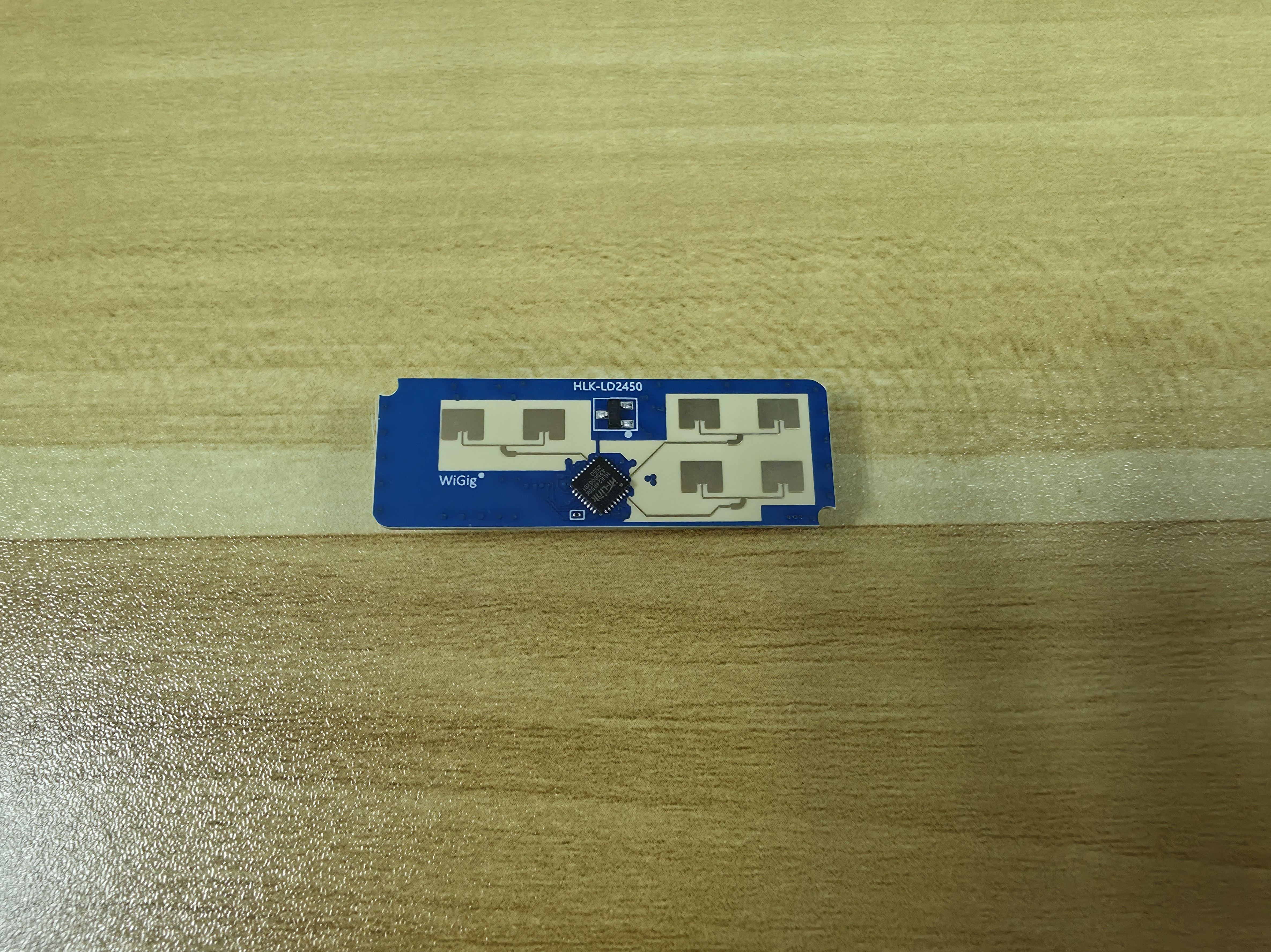
| LD2450-series mmWave radar | Yes | Presence acquisition, coordinates, and target tracking |
| LD2410C | Optional | Maintains an already established presence session |
| Panasonic EKMC1603111 PIR | Optional | Additional motion evidence |
| BH1750 | Optional | Ambient light |
| SHT4x | Optional | Temperature and humidity |
The current firmware and partition layout assume the 8 MB Flash / 8 MB PSRAM XIAO ESP32S3. Smaller-flash boards, boards without PSRAM, and other ESP32 families are not drop-in replacements.
| Seeed Studio XIAO ESP32S3 | Current dual-radar PCB |
|---|---|
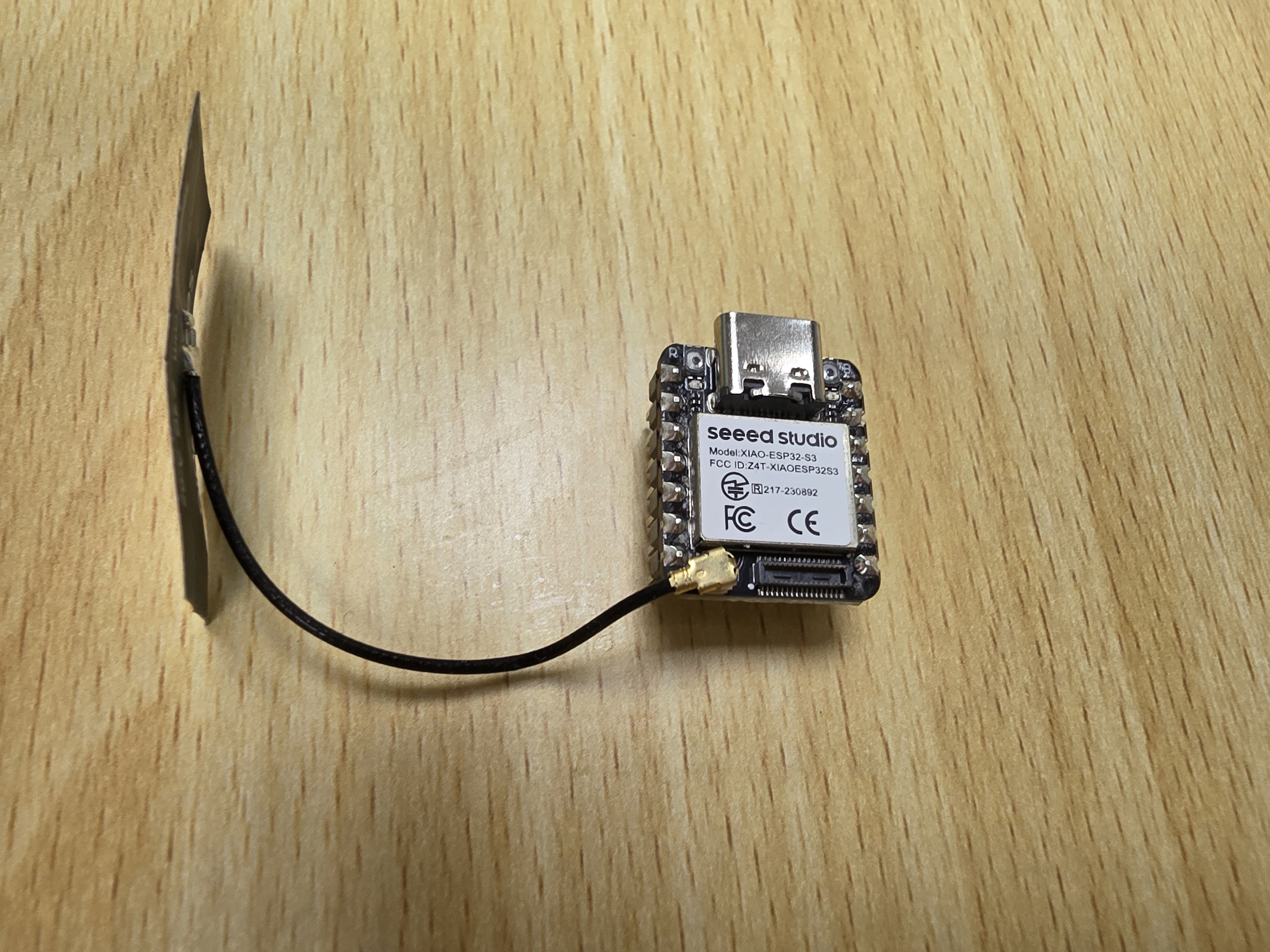 |
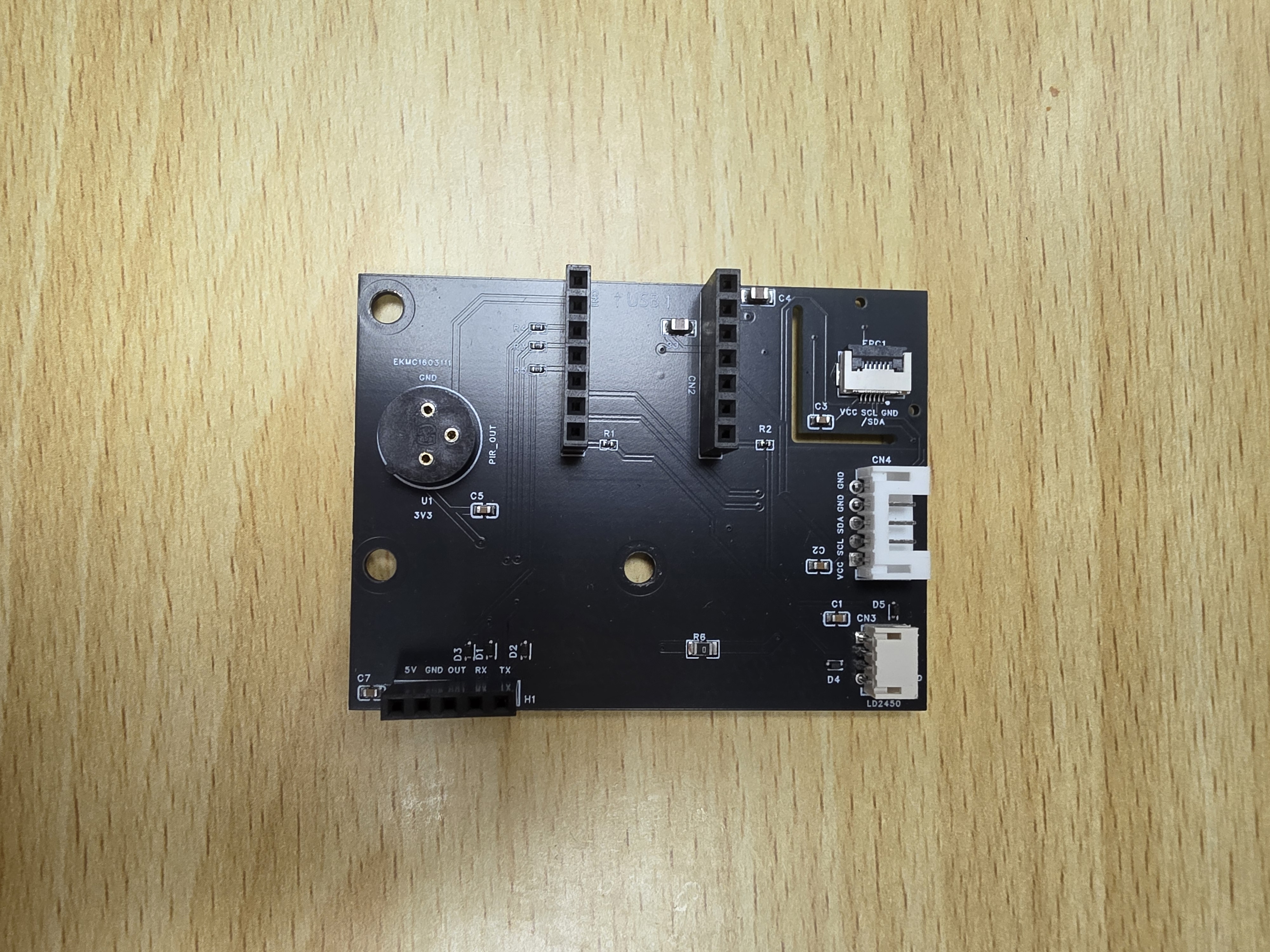 |
The dual-radar PCB shown above is the current manufacturing reference. The earlier single-radar PCB remains in the repository only as a legacy reference.
| Function | XIAO label | ESP32 GPIO | Connect to |
|---|---|---|---|
| PIR input | D0 | GPIO1 | PIR OUT |
| LD2410C UART TX | D1 | GPIO2 | LD2410C RX |
| LD2410C UART RX | D2 | GPIO3 | LD2410C TX |
| I2C SDA | D4 | GPIO5 | BH1750 SDA and SHT4x SDA |
| I2C SCL | D5 | GPIO6 | BH1750 SCL and SHT4x SCL |
| LD2450 UART TX | D6 | GPIO43 | LD2450 RX |
| LD2450 UART RX | D7 | GPIO44 | LD2450 TX |
| Status LED | Built-in LED | GPIO21 | XIAO user LED |
| Reset button | BOOT | GPIO0 | XIAO BOOT button |
The full current schematic is available in the repository:

UART TX and RX must be crossed:
- XIAO TX connects to radar RX.
- XIAO RX connects to radar TX.
- XIAO and every radar must share GND.
Do not identify TX and RX only by cable color. Check the label or module datasheet because cable orders differ between vendors.
GPIO3 is an ESP32-S3 strapping pin. The reference board connects it to LD2410C TX. Do not add a pull-up or pull-down resistor that can force an invalid boot strap level.
The reference schematic supplies the radar connectors from 5 V and the PIR/I2C sensor side from 3.3 V. Third-party breakout boards can have different regulators, level shifting, and pin orders.
Before connecting power:
- Confirm the exact module model and pin labels.
- Confirm its supply and UART logic-voltage requirements from the module datasheet.
- Check connector orientation with a multimeter when possible.
- Connect all grounds together.
- Power off the assembly before moving UART or sensor wires.
Do not assume that a pin marked VCC on a different module is safe at the same voltage.
BH1750 and SHT4x share GPIO5/GPIO6. Both modules must use compatible I2C addresses and voltage levels. Keep the bus short and verify that breakout-board pull-ups do not pull the bus above the XIAO's safe logic voltage.
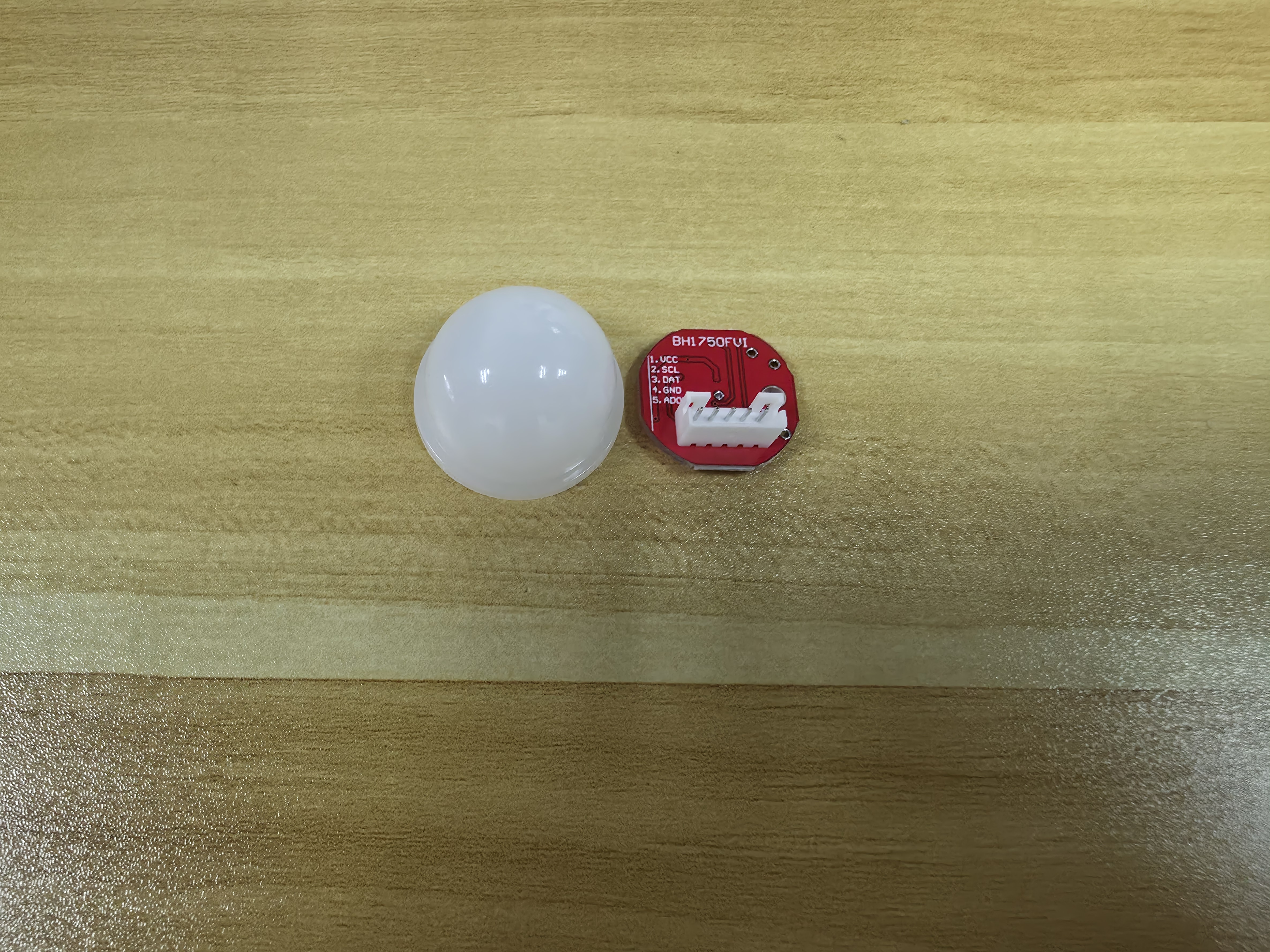
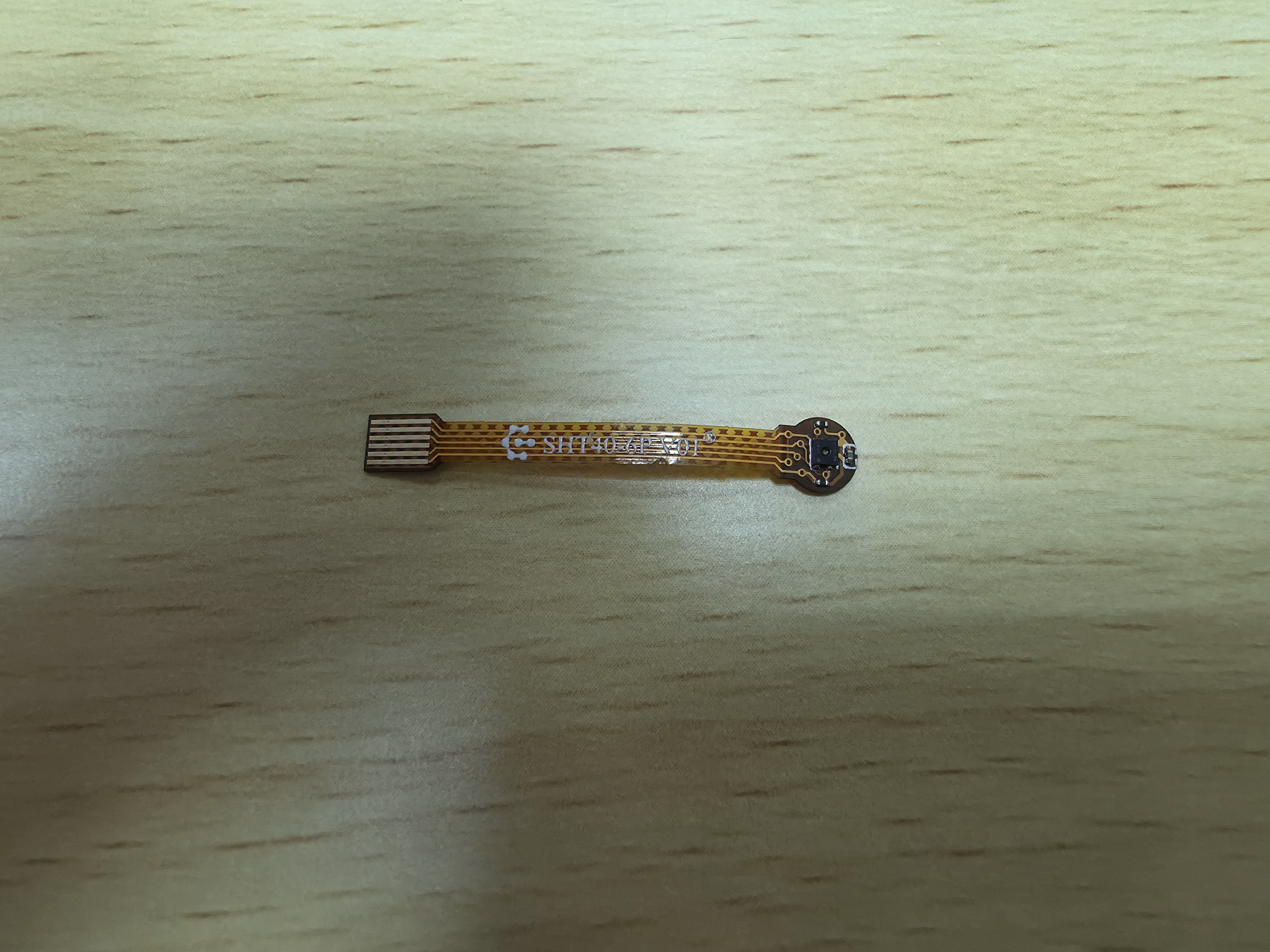
The primary radar is required for target coordinates, movement, target count, room placement, zones, and multi-device fusion. Firmware may boot without valid radar data, but spatial presence features cannot operate correctly.
LD2410C is optional. It can maintain a presence session that PIR or a confirmed primary-radar track already started. It cannot start occupancy by itself and does not create motion, coordinates, target count, room state, or zone occupancy.
Missing LD2410C hardware is ignored at runtime. If fitted, its gate sensitivity can be tuned from Zone Settings.
These sensors are optional. If PIR is omitted, keep GPIO1 electrically stable or remove its YAML configuration in a custom build. Floating GPIO1 can create false motion evidence.
- Inspect the PCB for shorts, reversed connectors, and solder bridges.
- Connect only the XIAO and USB, then verify that it boots.
- Disconnect power and add the primary radar.
- Boot again and confirm that targets appear.
- Add optional modules one at a time, powering off between changes.
- Verify temperature, humidity, light, PIR, and LD2410C status before closing the enclosure.
- Place the radar face against non-metallic material with a clear field of view.
This staged sequence makes a wiring fault easier to isolate.
| Initial enclosure assembly before fitting the bottom | Completed dual-radar enclosure |
|---|---|
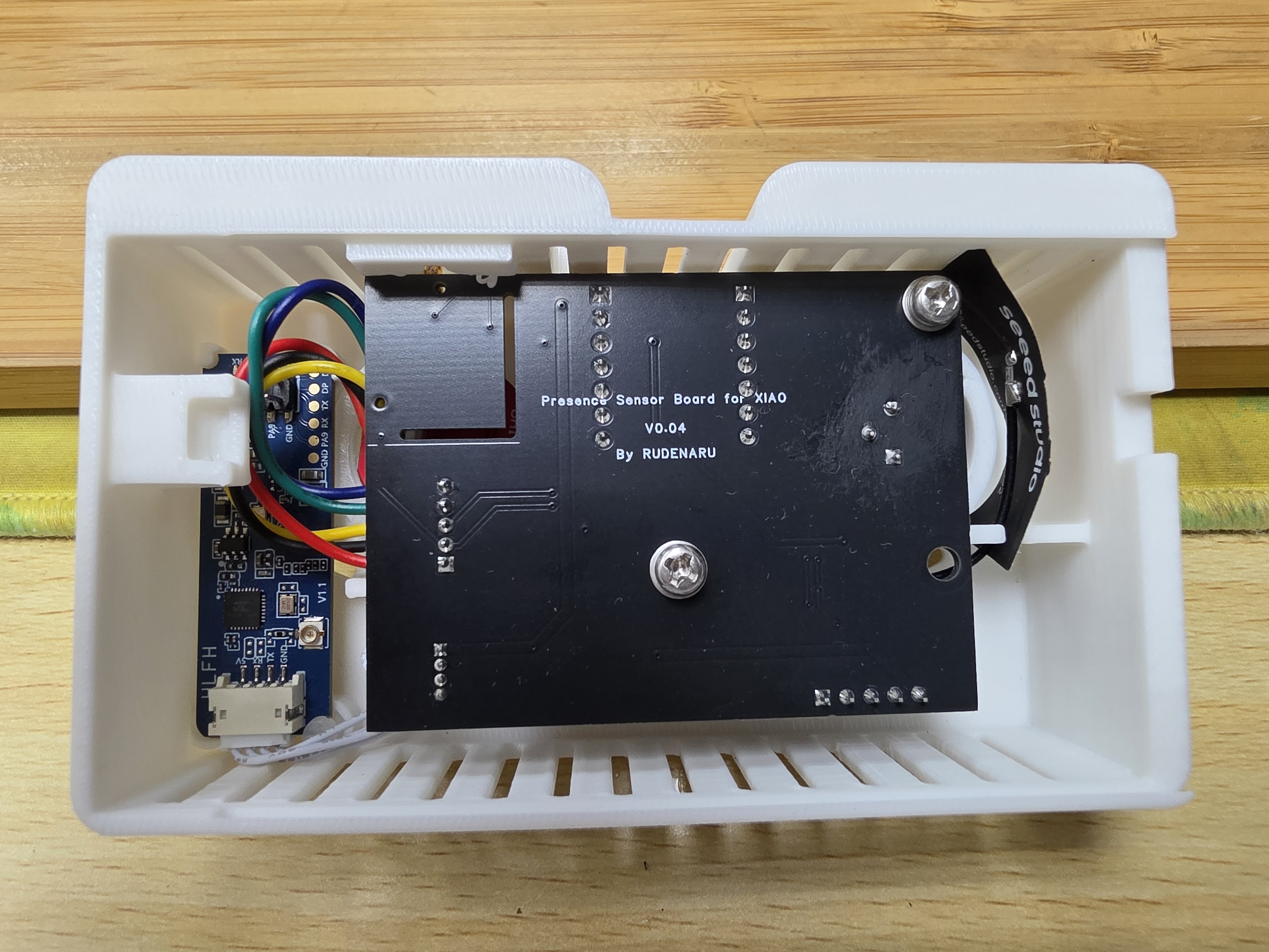 |
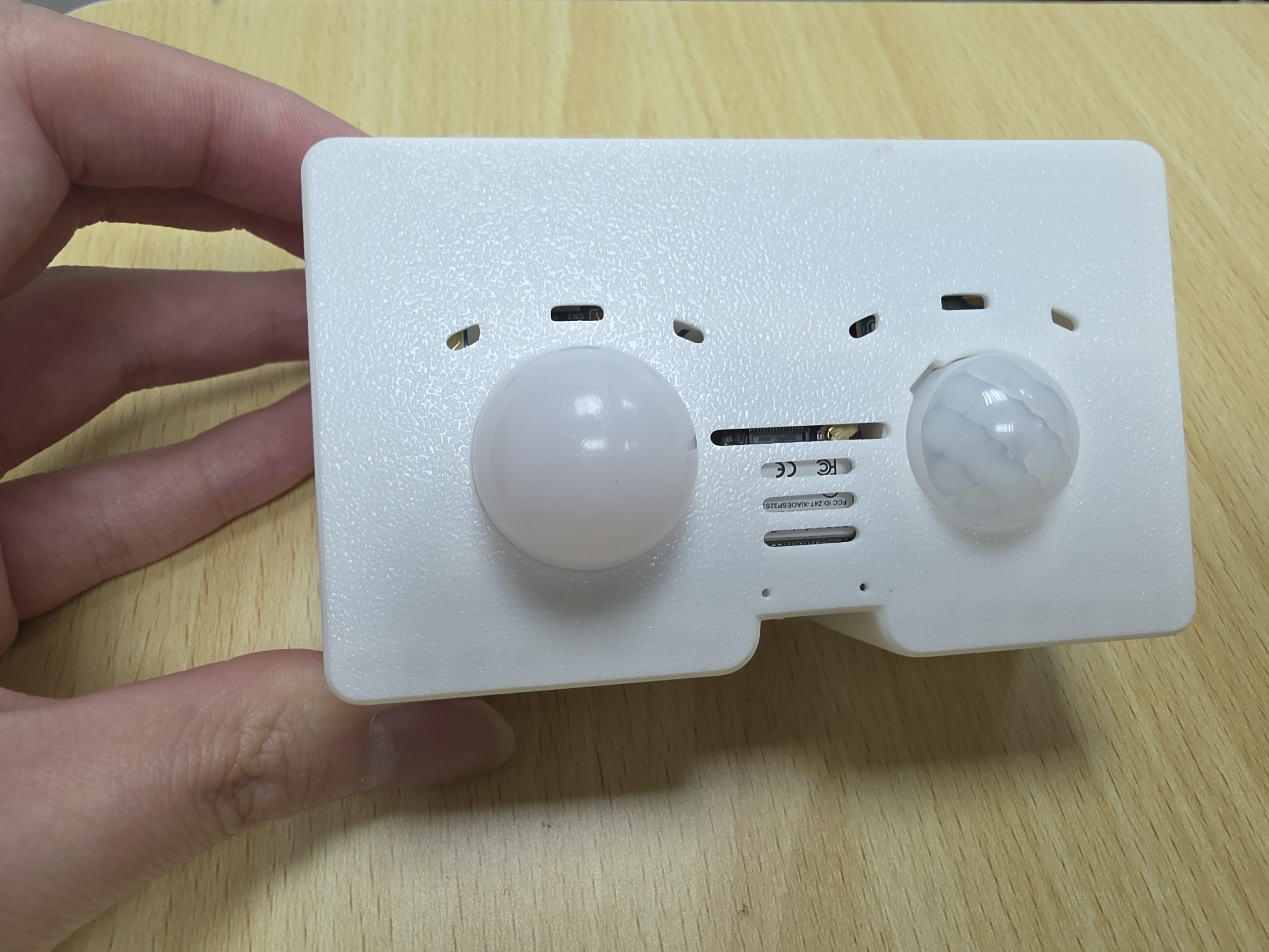 |
- Metal, dense wiring, power supplies, and large conductive objects near the radar face can distort detection.
- Glass and thin walls may allow detection outside the intended room.
- Confirm the actual radar direction before saving its floorplan placement.
- Avoid a mounting position where the enclosure or cable crosses the radar face.
- Use stable power; a marginal supply can look like Wi-Fi, UART, or random reboot trouble.
Use top_dual.3mf and bottom_dual.3mf for the current dual-sensor build. The unsuffixed top.3mf and bottom.3mf remain the legacy single-sensor enclosure. Because the locking interface changed, the legacy bottom.3mf cannot be reused with top_dual.3mf.
- The device appears over USB.
- The status LED and setup access point behave as described in Getting Started.
- The dashboard reports the primary radar as available.
- Coordinates move in the correct direction.
- Optional sensors report plausible values.
- No module or regulator becomes abnormally hot.
Disconnect power immediately if a component heats rapidly, voltage collapses, or the USB host repeatedly disconnects.