Repository navigation
8. LCC Slave PCB Usage
LCC Slave PCBs that I sell are available in two types, both boards are 12 volt powered at 2 amps MAX.
- Brushed motor controller (which includes model train locomotives)
- Stepper motor controller
✅ Both boards will work in the role of a switching controller.
Type 1 is a polarity-agnostic interfaced board with connectors for add-on peripherals (IR detector, DFRobot DFPlayer, RGB LED bus, limit switches, GPIO output, and H-bridge DC motor controller).
Type 2 has the DRV8825 driver onboard and is not polarity-agnostic, and provides connectors for add-on peripherals (stepper motor, IR detector, limit switches, and GPIO output).
These boards were intentionally designed to use certain devices as external peripherals to reduce their minimum required installation space. In the case of model trains, HO scale locomotives have an incredibly small amount of room to work with and I really don't have the time to make different PCBs to fit numerous brands and models. So I decided if they have the room to add something like a DFRobot DFPlayer and speaker, they can just add it on if they want to.
Again, these PCBs are intended for brushed and stepper motors up to 2 amps max. If you intend to run higher current motors and drivers, you should run their drivers' vmot/vmotor and ground terminals directly to your power supply and leave the LCC Slave to power its own circuitry through the PCB traces.
Since there are so many possible ways to use an MCP23017 GPIO expansion module, I didn't bother to create a PCB for these in a switching controller role. My recommendation is to set them on a breadboard style PCB and solder through the holes to attach it, then point-to-point things as necessary. This is the easiest way to make a PCB with 16 screw terminals for each GPIO output and it only takes an hour or two to build one.

All declarations below are of the PCB in the orientation exactly as it appears above. Keep in mind that this board is polarity-agnostic, The P1 and P2 pads are for 12 volts DC, but it doesn't matter which one is connected to positive or negative.
DFPlayer from top to bottom
- +5 volts
- Serial TX to DFPlayer RX
- Serial RX from DFPlayer TX
- Gnd
GPIO from left to right
- No connection
- Output 2 or I2C SCL
- Output 1 or I2C SDA
- No connection
👉 +3.3 volts for an MCP23017 GPIO expansion module is provided to the right
Limit from left to right
- No connection
- Limit switch 2
- Limit switch 1
- No connection
Motor Diver from left to right
- H-Bridge forward pin
- H-Bridge reverse pin
- H-Brdge PWM pin
- No connection
- Gnd
- +3.3 volts
- No connection
- +12 volts
IR Sens from left to right
- Gnd
- Data input
- Data input
- +3.3 volts
RGB LED from left to right
- Gnd
- Data output
- Data output
- +5 volts
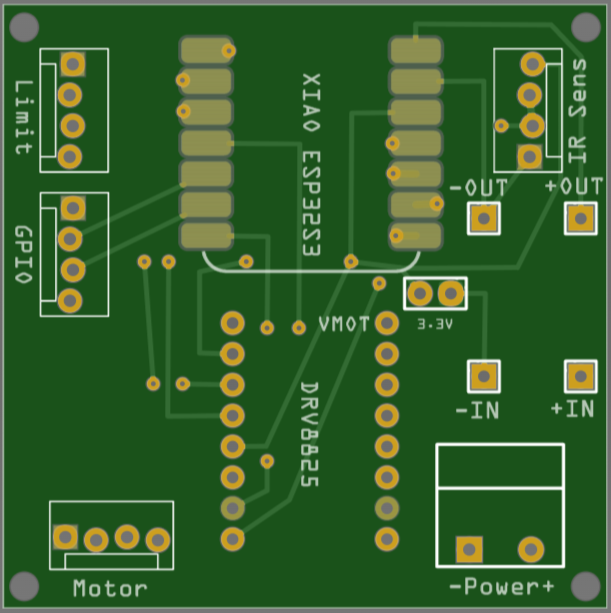
All declarations below are of the PCB in the orientation exactly as it appears above.
Limit from top to bottom
- No connection
- Limit switch 1
- Limit switch 2
- No connection
GPIO from top to bottom
- No connection
- Output 1 or I2C SDA
- Output 2 or I2C SCL
- No connection
👉 +3.3 volts for an MCP23017 GPIO expansion module is provided to the right
IR Sens from top to bottom
- +3.3 volts
- Data input
- Data input
- Gnd
Motor from left to right
- Coil 1A
- Coil 1B
- Coil 2A
- Coil 2B
LCC Slaves behave like an analog modem when connected to USB. Meaning, they respond to a custom set of Hayes style AT commands. You will need to use the Serial Monitor feature of the Arduino IDE or a terminal program with local echo enabled for this.
The LCC Slave type 2 does not leave the sleep pin to the DRV8825 high when the motor is idle. So you need to send it an AT+ENABLE to set the sleep pin high in order to set the current limit potentiometer. You can then send an AT+DISABLE to set it low again, or send the LCC Slave a /stepper/ command, or just reboot it.
There is no one-size/fits-all adjustment for the current limit, this all depends on your stepper motor and its intended use. But, an example procedure for a 1" thick Nema 17 would be to use a volt meter with aligator clips on the probes, the negative clipped to the negative power line and the positive clipped to a small Philips jeweler screwdriver.
Adjust the potentiometer until you have a 0.5 volts on the volt meter and call it good. If you notice that your motor struggles too much against a load, increase it by .1 volts at a time until the problem goes away. If you can't fix it by allowing more current draw, then you probably have a defective motor or it's too small and you're expecting too much from it. You may want to consider a stepper with a built-in planetary gear box.