Repository navigation
Accidents
Note
Design stage. This page describes planned mechanics from the design document. Not implemented yet — see Roadmap (milestone M10: accident models, containment, DamageBudget, server damage modes).
Accidents in Prompt Critical are not scripted events. There is no "LOCA button" and no meltdown animation. A pipe breaks — because you broke it, because pressure exceeded its strength, because it wore out, because a creeper exploded next to it — and then the ordinary physics of the plant takes over: flashing, blowdown, boiling crisis, zirconium oxidation, hydrogen, fuel damage. Whatever happens next emerges from the same models that run the plant every tick.
| # | Principle | Consequence |
|---|---|---|
| A1 |
Accidents are not scripted. A break adds BREAK links and sources to the fluid network; normal physics does the rest |
no canned animations or fixed outcomes |
| A2 | Every consequence passes through barriers: fuel matrix → fuel cladding → primary circuit boundary → containment. Damage to the world is possible only when all barriers are breached | barrier matrix below; radiation and damage interfaces |
| A3 | The operator sees an accident only through instruments and sound. True cladding oxidation, peak cladding temperature or melt fraction are never shown — you see core exit thermocouples, vessel level, containment pressure and hydrogen, radiation monitors | each scenario lists "what the operator sees and hears" |
| A4 |
Accident time is real time for hydraulics and the first ~15 minutes of decay heat; the long tail is compressed by K_slow = 72
|
timelines below are in physical time |
| A5 |
Consequences are proportionate and limited by the server. All destruction goes through DamageBudget
|
see "Consequences in the world" |
flowchart LR
    IE[Initiating event<br/>break, failure, Lua error,<br/>nearby explosion, Create overload] --> PH[Plant physics<br/>hydraulics / kinetics / heat transfer]
    PH --> AM[AccidentModels<br/>Zr oxidation, H2, cladding,<br/>fission product release, melt]
    AM --> PH
    AM --> BAR{Barriers}
    BAR -->|intact| OK[No consequences for the world]
    BAR -->|breached| ST[Source term → radiation:<br/>dose, contamination]
    AM --> CON[AccidentConsequence → DamageBudget]
    AM --> EV[Events → sound,<br/>annunciator]
There is no random accident generator by default. Initiating events come from the world:
| Source | Example |
|---|---|
| Player action | broke a pipe block, opened the wrong valve, pulled the rods |
| Mechanical overload | pressure above pipe strength, water hammer, Create stress exceeded |
| Wear | fatigue, steam generator tube corrosion |
| Control system error | Lua closed the feedwater, set the main coolant pumps to zero |
| External impact | nearby explosion, falling blocks, a creeper |
| Random failures |
optional: accident.random_failures.enabled = false by default |
| Scenario | Class | Main barrier at risk |
|---|---|---|
| LOCA (small / medium / large, double-ended break) | design basis | cladding, then containment |
| Loss of flow, pump coastdown, station blackout (SBO) | anticipated → beyond design basis (SBO) | cladding (DNB) |
| ATWS (failure to scram) | beyond design basis | primary boundary (pressure) |
| Reactivity accidents: rod ejection, prompt criticality, boron dilution | design / beyond design basis | fuel, cladding |
| Steam generator tube rupture (SGTR) | design basis | containment (bypass) |
| Hydrogen: radiolysis, steam–zirconium reaction, deflagration, detonation | beyond design basis | containment |
| Cladding failure and fission product release | consequence of others | cladding |
| T1 lesson: runaway after the iodine pit | beyond design basis, T1 | all |
| Core melt, corium, steam explosion | severe accident | vessel, containment |
| Tier-specific: Wigner energy and graphite fire (T0), positive void effect in LOCA (T1/T3) | — | — |
A break appears when a block of a pressurized pipe or vessel is removed (by a player or an explosion), or when pressure exceeds the element's strength (Barlow formula with temperature-dependent steel strength: 520 MPa at 20 °C, 440 at 300 °C, 300 at 500 °C, 150 at 700 °C). A pipe_large DN400 (Ø426×32 mm) bursts at 66 MPa — 4× margin over 15.5 MPa. Removing a pipe block makes a double-ended guillotine break (DEGB): both ends discharge. Cracks can grow over time (leak before break), so leak detection can catch them early.
Break classes for the PR-300 reference reactor:
| Class | Diameter | Initial flow | Compensated by |
|---|---|---|---|
| Leak | < 10 mm | < 8 kg/s | makeup 5 kg/s |
| Small LOCA | 10–50 mm | 8–200 kg/s | high-pressure injection pumps (2 × 15 kg/s) |
| Medium LOCA | 50–150 mm | 0.2–1.8 t/s | HPI + accumulators |
| Large LOCA | > 150 mm | > 1.8 t/s | accumulators + low-pressure injection |
| DEGB of the main pipe | 2 × DN400 | ≈ 25 t/s for tens of ms, then 5–8 t/s | accumulators + LPI |
Break flow is critical (choked) flow, by the homogeneous equilibrium model by default or Moody (conservative) in a "licensing" hardcore mode. In a DEGB, pressure drops from 15.5 MPa to saturation (11.3 MPa) in about 5 ms — within one tick, handled by substeps.
- Blowdown. Two-phase discharge; the core dries out; DNB within 0.5–2 s. The reactor shuts itself down (negative void coefficient in a light-water reactor), plus a trip. Stored heat in the fuel moves into the cladding: the first peak cladding temperature.
- Refill. Accumulators (nitrogen at 4 MPa) inject into the cold legs; some water is swept out of the break (ECC bypass emerges naturally from the node model). The core has no cooling and heats up adiabatically on decay heat: 2.6 K/s at 10 s, 1.7 K/s at 100 s.
- Reflood. Water rises from below; the quench front moves at ~1–5 cm/s; above it, steam and droplets — the second temperature peak.
-
Long-term cooling. Low-pressure pumps from the
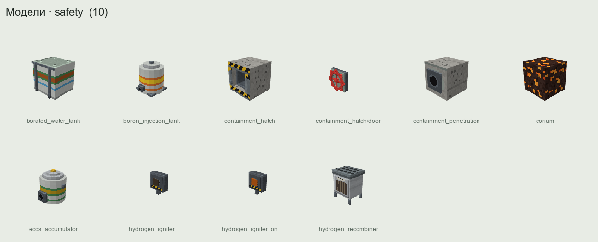
borated_water_tank, then recirculation from the containment sump. Optional: insulation debris from destroyed blocks clogs sump screens.
| System | Model | PR-300 parameters |
|---|---|---|
Accumulators (eccs_accumulator) |
water + nitrogen, isolated by check valves | 2 × 6 m³ (4 m³ water at 2000 ppm boron, 2 m³ N₂ at 4.0 MPa); empty in 20–30 s in a large LOCA |
| High-pressure injection | pump on a Create shaft | 2 × 15 kg/s, shutoff 12 MPa, 2000 ppm |
| Low-pressure injection | same | 2 × 60 kg/s, shutoff 2 MPa |
Borated water storage tank (borated_water_tank) |
tank with level | 200 m³, 2000 ppm |
Boron injection tank (boron_injection_tank) |
tank, injected by HPI | 4 m³, 7000 ppm |
| Containment sump | separated node | recirculation when the tank drops below 10 % |
ECCS pumps are Create-kinetic. Without rotation (station blackout) they do not work, and the passive accumulators are the only protection. This is one of the main design incentives to build an independent source of rotation (a diesel or emergency steam turbine drive).
Containment is a gas-mixture node (N₂, O₂, H₂, steam) with a liquid sump. Heat sinks: condensation on containment_wall concrete and steel (Uchida correlation, or Tagami as an option), sprays, and a leak rate of 0.1 %/day at design pressure — the pathway for releases.
Estimate: all 20 t of PR-300 primary water at 300 °C into a 4500 m³ containment without heat sinks gives 0.455 MPa, 136 °C. With concrete walls, the peak is about 0.30–0.35 MPa in the first 30–60 s. So the PR-300 containment must be designed for ≥ 0.45 MPa; a smaller volume means higher pressure.
| t | Event |
|---|---|
| 0 | break; ≈ 25 t/s; sound — impact and roar |
| 0.005–0.05 s | pressure 15.5 → 11 MPa; flashing in the hot leg |
| ~0.3 s | trip on high containment pressure; void has already shut the reactor down |
| 0.5–2 s | DNB on most rods; first cladding peak ≈ 700–850 °C |
| 1 s | safety injection signal |
| 3–4 s | below 4 MPa — accumulators open |
| 5–8 s | end of blowdown: primary ≈ containment pressure (0.25–0.35 MPa) |
| 8–30 s | refill; adiabatic heat-up 2–2.6 K/s; LPI pumps start (if there is Create rotation) |
| 15–40 s | ballooning and burst of some rods (≈ 800 °C); gap release; containment activity monitors |
| 30–200 s | reflood, second peak; with LPI working, 900–1100 °C without core damage |
| 200–600 s | core covered, long-term cooling, switch to recirculation |
| without LPI | after the accumulators empty, the core boils dry again in ≈ 1 physical hour (0.5–3 real hours); cladding above 1200 °C — transition to a severe accident |
| t | Event |
|---|---|
| 0 | leak ≈ 49 kg/s; 5 kg/s makeup cannot keep up; hissing |
| 0–60 s | pressurizer level and pressure fall; heaters cannot help |
| ≈ 60 s | trip on low primary pressure (13.7 MPa); turbine trips |
| 1–2 min | safety injection at 12.5 MPa; HPI delivers 30 kg/s at ~8–10 MPa |
| 2–10 min | pressure settles near saturation at secondary temperature (7–8 MPa) while steam generators remove heat |
| 10–30 min | if HPI fails — core uncovers from the top, core exit temperature > 350 °C; the operator must cool down via the secondary side (steam dump) to reach accumulator/LPI pressure, or use feed and bleed |
| Symptom | Tag | Alarm | Sound |
|---|---|---|---|
| falling pressurizer pressure and level |
rcs.pressurizer.pressure, rcs.pressurizer.level
|
"Primary pressure low", "Pressurizer level low" | — |
| rising containment pressure, temperature, humidity |
cnt.pressure, cnt.temperature, cnt.humidity
|
"Containment pressure high" | jet roar, impact at the break |
| rising sump level | cnt.sump.level |
"Sump level" | — |
| makeup/letdown imbalance |
rcs.leak.rate (computed mass balance) |
"Primary leak" | — |
| subcooling margin | rcs.subcooling.margin |
"Subcooling < 15 K" | — |
| vessel level | core.level.rvlis |
"Reactor level low" | boiling in the vessel |
| core exit temperature | core.exit.temperature |
"CET > 650 °C" — entry to severe accident guidelines | — |
| containment activity | rad.cnt.dose_rate |
"Containment activity high" | dosimeter crackle |
Mitigation is design (passive accumulators, redundant ECCS with independent drives, leak detection), operator action (secondary cooldown, stopping pumps on loss of subcooling, manual ECCS start, recirculation, feed and bleed), and Lua automation — you can write a LOCA detector based on mass balance that starts ECCS before the setpoint. That is the gameplay (pillar P3).
Natural circulation. After the pumps stop, flow is set by the balance of gravity head and losses. This is a design requirement for the player: steam generators must be above the core. PR-300 with a 6 m elevation difference removes 3 % of power with a 30–40 K core temperature rise. If the steam generators are below the core, there is no natural circulation and any blackout leads to boiling in the core.
Station blackout means losing all sources of Create rotation for the main coolant pumps, feedwater pumps and ECCS pumps (and FE for electric valve drives, if you built it that way).
| t (physical) | t (real) | Event |
|---|---|---|
| 0 | 0 | rotation lost; pumps coast down; rod drives release the rods |
| 0–60 s | 0–60 s | natural circulation; steam generators boil, steam dumps through their relief valves (loud) |
| 13 min | 13 min | main coolant pump seals without cooling leak 1.3 kg/s each; with 20 % probability a seal fails: 15 kg/s per pump — a small LOCA |
| ≈ 5.7 h | ≈ 75 h | steam generators dry out — if there is no seal leakage |
| 2–4 h | 2–4 h | with seal leakage: ~20 t of coolant lost (leakage runs on real time); with failed seals, in 10–15 min |
| later | later | core uncovers → severe accident |
Because the long decay heat tail is compressed, the main SBO threat in the game is coolant leakage, not steam generator boil-off. nuclide.decay_heat_clock = REAL_TIME restores the physical timescale for hardcore servers.
The operator hears silence in the turbine hall (no pump or turbine tone) and the roar of steam relief on the roof. Mitigation: an independent rotation source — a Create steam turbine driving emergency feedwater from steam generator steam, which works as long as there is steam; passive systems (elevated tank, gravity feed to the steam generators); mobile pumps.
Causes in game:
- The protection cabinet is damaged by an explosion or earthquake without losing power (common-cause failure), or the player disabled trip functions at the cabinet. Real operating rules forbid it; the mod does not, and the consequences are honest.
- Rods jam mechanically (channel deformation above 900 K or seismic event).
- A T1 design with servo-only drives and no Create rotation: rods do not fall by themselves.
Physics. Without rods, power settles where feedbacks balance. A light-water reactor with negative moderator coefficient finds a stable new equilibrium at lower power and higher temperature. The danger is pressure: coolant expands, the pressurizer goes solid, relief valves open. For an ATWS with loss of feedwater and turbine trip in PR-300, coolant temperature rises ≈ 30 K and pressure peaks at 18–21 MPa. Early in the cycle (high boron, MTC ≈ −10 pcm/K) the peak is higher.
ATWS in T1 (positive void coefficient): there is no equilibrium — more power, more steam, more power. Only Doppler limits it, and reactivity heads towards β.
| t | Event | Response |
|---|---|---|
| 0 | loss of feedwater; turbine trips; scram fails | annunciator "Trip mismatch: signal present, rods not in" |
| 10–60 s | coolant temperature and pressurizer level rise | manual trip from another circuit; drive rods in with the normal drive |
| 60–120 s | pressurizer solid, relief valves open | boron injection: HPI from the 2000 ppm tank + boron_injection_tank at 7000 ppm |
| 2–10 min | boron reduces power (300–400 ppm needed, ≈ 40–60 s of injection) | emergency feedwater to the steam generators |
| > 10 min | cooldown | — |
A crack in the control rod drive housing on the vessel head (wear, or a control_rod_drive block damaged by an explosion). 15.5 MPa across the drive shaft area pushes a rod cluster out in ≈ 0.04 s, and the open nozzle is also a small LOCA. Worth of the ejected cluster comes from the nodal model with local flux distortion: 0.7–1.0β from a fully inserted bank at hot zero power, 0.1–0.2β at power. If you design a rod cell with a single cluster worth 2000 pcm, ejecting it gives ~3β — prompt criticality and a severe RIA. Limiting the worth of any single rod is a direct design lesson.
Above β, the reactor behaves per the Nordheim–Fuchs model: a symmetric sech² pulse stopped by Doppler feedback, after which the reactor "bounces" subcritical by the same amount it was above prompt critical.
PR-300 values:
| ρ₀ | Energy | Mean fuel enthalpy added | Peak (×4 local peaking) | Peak power | Pulse width |
|---|---|---|---|---|---|
| 1.2β | 470 MJ | 8 cal/g | 32 cal/g | 8 GW | 52 ms |
| 1.5β | 1.17 GJ | 20 cal/g | 80 cal/g | 50 GW | 21 ms |
| 2.0β | 2.34 GJ | 40 cal/g | 160 cal/g | 200 GW | 10 ms |
| 3.0β | 4.7 GJ | 80 cal/g | 320 cal/g | 800 GW | 5 ms |
The damage measure is peak radially averaged fuel enthalpy at the hot spot:
| Threshold | Value | Mechanism | Consequence |
|---|---|---|---|
| PCMI cladding failure | max(60, 150 − 1.6·Bu) cal/g (Bu in MW·d/kg) | fast pellet expansion cracks brittle cladding | cladding failure, gap release |
| High-temperature failure | 170 cal/g (fresh fuel) | film boiling after the pulse | cladding failure |
| Fuel fragmentation and dispersal | 230 cal/g | hot dispersed fuel meets water | local steam explosion |
| Centerline melting | 3120 K | — | melt fraction |
Initiators: clean water fed by mistake (operator or Lua picked the wrong tank), or an unborated condensate slug collected in a loop during a small LOCA and then pushed into the core when a pump is restarted. A 3 m³ slug of clean water into PR-300 at 1000 ppm gives ≈ 500 ppm at the core inlet → +3700 pcm ≈ 5.4β with rods withdrawn at hot zero power — a catastrophic RIA. With rods inserted (−8000 pcm) it is safe. Lesson: boron first, then pumps. A boron concentration interlock on pump suction is a job for your Lua control system.
A guillotine break of one Ø16×1.5 mm tube leaks ≈ 17 kg/s from primary to secondary; 5 kg/s makeup cannot keep up.
Why it matters: it is a containment bypass. Radioactive coolant goes to the secondary side, steam lines, turbine and condenser (air ejectors release noble gases to ventilation), and if the steam generator overfills, through its relief valves directly to the atmosphere.
| Symptom | Tag | Time |
|---|---|---|
| N-16 in the steam line (7.13 s half-life; core-to-SG transit 2–5 s) | rad.steamline1.n16 |
seconds — earliest sign |
| condenser off-gas and SG blowdown activity |
rad.condenser.offgas, rad.sg1.blowdown
|
1–3 min |
| rising level in one steam generator with reduced feed | sg1.level.wide |
minutes |
| falling pressurizer level and pressure, rising makeup | rcs.pressurizer.* |
minutes |
| steam/feed flow mismatch on one SG |
sg1.flow.steam, sg1.flow.feed
|
minutes |
| t | Event | Action |
|---|---|---|
| 0 | rupture, 17 kg/s | — |
| 5–30 s | N-16 alarm | diagnose |
| 3–10 min | trip on low pressure or manual; safety injection at 12.5 MPa | isolate the faulted steam generator |
| 10–30 min | primary pressure stabilizes, leak continues | cool down through the intact SG, reduce primary pressure to the faulted SG's pressure — the leak stops |
| if not done | faulted SG overfills, water reaches the steam line, its relief valve dumps water and may stick open (30 % probability) | unisolable release to the atmosphere |
Zr + 2 H₂O → ZrO₂ + 2 H₂, releasing ≈ 6.4 MJ per kg of Zr. Kinetics follow a parabolic law: Cathcart–Pawel (realistic, 1273–1800 K) and Baker–Just (conservative, above 1800 K). Equivalent cladding reacted (ECR) is tracked per group.
Time to 17 % ECR at constant temperature:
| Temperature | Baker–Just | Cathcart–Pawel |
|---|---|---|
| 1000 °C | 2.8 h | 3.5 h |
| 1100 °C | 46 min | — |
| 1204 °C | 14 min | 24 min |
| 1300 °C | 5.5 min | 10.5 min |
| 1500 °C | 64 s | — |
Runaway oxidation. At 1300 °C oxidation heat is ≈ 51 kW/m² — 15 times the decay heat at the surface. That is the physical meaning of the 1204 °C limit: above ~1200 °C oxidation heats itself, and the core heads to cladding melting (2098 K) within minutes.
Steam starvation limits the reaction to the available steam. The paradox the player should feel: flooding an overheated core first sharply increases hydrogen production (most of the hydrogen at TMI-2 came when pumps were restarted). Radiolysis of water is a separate, slower hydrogen source.
PR-300 has 3.58 t of zirconium; full oxidation gives 158 kg of H₂ and 23 GJ of heat. In a 4500 m³ containment:
| Zr oxidized | H₂ in dry air |
|---|---|
| 1 % | 0.44 % |
| 5 % | 2.2 % |
| 17 % | 7.0 % |
| 30 % | 11.7 % |
| 100 % | 30.6 % (stoichiometric is 29.6 %) |
| Regime | Condition (H₂ fraction x, steam s) | Load |
|---|---|---|
NONE |
x < 4 % + 0.11·s, or steam > 55 %, or O₂ < 5 % | — |
SLOW_DEFLAGRATION |
flammable but < 8 % (upward, incomplete burn) | quasi-static |
COMPLETE_DEFLAGRATION |
8–10 % | quasi-static, 0.7–1.0 × AICC pressure |
FAST_DEFLAGRATION |
≥ 10 % (flame acceleration) | dynamic ≈ AICC pressure, 10–100 ms pulse |
DETONATION |
18 % + 0.3·s ≤ x ≤ 59 % − 0.6·s, or deflagration-to-detonation at ≥ 13 % in a large enough volume | ≈ 2 × AICC, reflected up to 2.5× more, milliseconds |
Adiabatic isochoric complete combustion (AICC) pressure ratio: 2.3 at 4 % H₂, 3.5 at 8 %, 4.2 at 10 %, 5.8 at 15 %, ~8 at stoichiometric. Conclusion: full oxidation of the PR-300 core in a 4500 m³ containment without recombiners is a detonable mixture and destroys the containment; 30 % oxidation means a fast burn of ~4 bar.
Ignition sources: hot surfaces above 858 K (always), overheated recombiners above 8 % H₂, electrical sparks, redstone or fire in the volume, hydrogen_igniter (deliberately burns small portions at 4–6 %), lightning or an external explosion.
Passive autocatalytic recombiners (hydrogen_recombiner) convert H₂ to water on a Pt/Pd catalyst without flame, ≈ 0.5 g/s at 4 % H₂ and 1 bar. A PR-300 severe accident generates ~10–50 g/s at peak, so you need dozens of recombiners — or igniters and sprays. Working out how many is your job.
What the operator sees: cnt.h2.fraction (gas analyzers with 30–120 s delay), cnt.o2.fraction, cnt.steam.fraction, recombiner temperatures cnt.par*.temperature (an indirect hydrogen indicator). Sound: a low thump of deflagration, the crack of detonation. Alarms "H₂ in containment > 2 %", "> 4 %", "Recombiners active".
Each channel group tracks the fraction of rods in each damage state:
| State | Entry condition | Release | Geometry |
|---|---|---|---|
INTACT |
— | none | normal |
DEFECTIVE |
small defects: pellet-cladding interaction, fretting, fabrication defects | constant small leakage | normal |
BALLOONED |
hoop stress above creep strength | none | partial channel blockage |
BURST |
cladding above burst temperature | gap gases | blockage |
OXIDIZED_BRITTLE |
ECR > 17 % or peak cladding > 1204 °C | — | shatters on reflood (thermal shock) |
FRAGMENTED |
brittle cladding on reflood, or RIA above PCMI threshold | gap + part of volatiles | fragments, pellet relocation |
MELTED_CLAD |
cladding above 2098 K | + diffusion release | Zr runs down, dissolves UO₂ |
MOLTEN |
fuel melt fraction > 0.5 | early in-vessel release | corium |
Pellet-cladding interaction (PCI): once the gap closes (burnup above ~30 MW·d/kg), a fast power increase of more than 12 kW/m over the "conditioned" level within an hour, to above 25 kW/m, fails a fraction of rods. This is why real plants limit power ramp rates after refueling.
Ballooning and burst: in a LOCA, internal rod pressure reaches ≈ 7.3 MPa, hoop stress ≈ 39 MPa, and rods burst around 800 °C (NUREG-0630 data). Burst rods partly block the channel, worsening cooling on reflood.
Release: on failure, the gap inventory (at least 5 % of noble gases, halogens and alkali metals) is released. Overheated fuel releases more by diffusion (CORSOR-M: ≈ 2 %/min at 2000 K, ≈ 40 %/min at 2500 K), up to group limits from NUREG-1465: noble gases 100 %, halogens 40 %, alkali 30 %, Te 5 %, Ba/Sr 2 %, Ru 0.25 %, refractory 0.05 %. Released activity enters the coolant; noble gases go to the gas phase; iodine mostly stays in alkaline water.
Iodine spiking: with defective rods, a depressurization above 1 MPa or a power change above 15 % releases 1 % of their gap iodine over ~1 physical hour — coolant I-131 rises 10–100 times.
Cladding failure is not directly measurable. You see coolant activity (rad.letdown.activity), off-gas activity, and in a severe accident the high-range containment monitors. A "percent of failed rods" readout must never be shown (pillar P2).
This scenario is not scripted either. It emerges if a player with a T1 reactor repeats errors physically similar to the events of 1986. Every link is an existing model:
| # | Link | Model |
|---|---|---|
| 1 | long operation at reduced power, then a drop almost to zero | xenon builds up, the top of the core is suppressed, flux shifts down |
| 2 | to raise power, the operator withdraws almost all rods |
operating reactivity margin falls below the minimum (tag core.reactivity.operational_margin, in equivalent rods) |
| 3 | low power with high flow and low inlet subcooling | steam appears low in the core; small changes in flow or pressure change void a lot; power coefficient positive at low power |
| 4 | flow drops (pump coastdown during a test) | more steam → positive void effect (+10…+30 pcm/% void) → more power |
| 5 | scram pressed | servo-only drive at 0.4 m/s; graphite displacers replace water at the bottom → positive reactivity where the flux is |
| 6 | ρ > β | prompt critical excursion (period 0.1–0.3 s with Λ ≈ 6·10⁻⁴ s); fuel enthalpy > 230 cal/g |
| 7 | fuel fragmentation → steam explosion in channels → channel tubes rupture | reactor cavity pressure exceeds its strength |
| 8 | steam–zirconium reaction, graphite in air | hydrogen, graphite fire |
Timeline of the in-game reconstruction (T1 reactor 20×20×7, 1200 fuel nodes; the test checks the qualitative sequence, not the numbers):
| t | Event | What the operator sees and hears |
|---|---|---|
| −24 physical h (−20 real min) | power reduced to 50 % | xenon rising (core.reactivity.xenon) |
| −1 physical h | power drops to ~1 % (controller error) | period, power; "Operating margin low" |
| −30 physical min | rods withdrawn, power ~7 % | margin below 15 equivalent rods — alarm |
| 0 | "test" begins: some pumps tripped, coastdown | flow falls, steam rises, power climbs; rumble in channels |
| +30 s | power rising with a 10–20 s period |
SHORT_PERIOD (if the player kept that setpoint) |
| +36 s | scram (manual or on period) | rods start moving |
| +37–39 s | displacers add reactivity; ρ → β | period 0.1–0.3 s; alarm bells |
| +39–40 s | prompt criticality; enthalpy > 230 cal/g; fuel–coolant interaction in channels | impact; PromptCriticalEvent
|
| +40–43 s | channel ruptures, cavity pressure rise, upper plate lifts | explosions |
| later | graphite fire, release from the open core | radiation |
How to avoid it: never withdraw rods below the minimum operating margin; do not run at low power; wait for xenon to decay (≈ 20–30 real minutes). How to fix the design (available in progression): shorten the displacers and remove the water column below them, add a fast gravity-release scram, raise enrichment (smaller void coefficient), add absorbers. Each change shifts the coefficients emergently.
The presentation is deliberately an engineering lesson without direct references.
| Stage | Threshold | What happens |
|---|---|---|
CLAD_BALLOONING_BURST |
1000–1200 K | ballooning and burst |
RAPID_OXIDATION |
> 1500 K | runaway oxidation, H₂ |
CONTROL_MATERIAL_RELOCATION |
Ag-In-Cd melts at 1073 K; B₄C–steel eutectic ≈ 1500 K | absorber runs down → local loss of rod worth — risk of recriticality if flooded with unborated water |
CLAD_MELT_CANDLING |
2098–2123 K | molten Zr runs down, dissolves UO₂, refreezes lower — channels block |
CERAMIC_MELT_POOL |
(U,Zr)O₂ ≈ 2800 K; UO₂ 3120 K | molten pool in the core surrounded by a crust |
LOWER_PLENUM_RELOCATION |
crust fails | corium in the lower plenum, interaction with water |
LOWER_HEAD_FAILURE |
see below | corium leaves the vessel |
EX_VESSEL_MCCI |
— | corium on concrete |
Coolability. The fraction of relocated and debris mass decides whether water still helps: below 0.1 flooding cools the core (with a hydrogen burst); 0.1–0.5 partly (thin debris beds with water on top); above 0.5 a melt pool, water on top removes only ~0.2–0.5 MW/m² through the crust. The operator does not get this number — only core exit temperature and level.
Vessel failure. With the reactor cavity flooded from outside (if you built a cavity flooding system), the lower head is cooled by external boiling up to ≈ 1.2 MW/m², and the vessel can hold the corium (in-vessel retention). Without external cooling, the head fails by creep at 1300 K wall temperature if primary pressure is above 10 MPa, or 1500 K below 1 MPa. Failure at high pressure disperses corium into the containment atmosphere (direct containment heating), hence the severe accident strategy: depressurize the primary before the vessel fails.
Steam explosion (fuel–coolant interaction): melt falling into more than 0.5 m of subcooled water triggers an explosion with 10 % probability; conversion efficiency 0.1–2 %. Example: 5 t of corium → 6.3 GJ of heat → 6–130 MJ of work ≈ 1.5–30 kg of TNT.
Molten core–concrete interaction: corium outside the vessel ablates concrete at ≈ 4.6 GJ per block of concrete or containment_wall. At 1 MW of decay power, one block every ~77 physical minutes (≈ 1 real minute). Ablation gases react with the metal in the corium to produce H₂ and CO. Rate is limited by DamageBudget. Water on top of a crusted corium can stop ablation.
T0: Wigner energy and graphite fire. Graphite irradiated below ~250 °C stores Wigner energy (up to ~2000 J/g). It releases when heated ~50 K above the irradiation temperature, peaking around 200 °C; if the release rate exceeds graphite heat capacity, heating becomes self-sustaining. Graphite oxidizes in air above 400 °C, fast above 600–700 °C; uranium metal burns above ~600 °C. The annealing procedure (as at Windscale): a controlled power rise with reduced air flow to release the energy in portions. A mistake (local overheating, wrong thermocouples) leads to fire — Windscale 1957 reproduces emergently.
T1/T3: LOCA with positive void effect. In channel reactors a header or channel break increases void and power rises until the trip (CANDU: 2–3× power peak within ~1 s in a large LOCA, which is why it has two independent fast shutdown systems). The player needs a fast gravity-release scram and a short-period setpoint.
T2b (BWR): core steam goes straight to the turbine (N-16 and radiolytic gases in the turbine hall). On a turbine trip, pressure rises, voids collapse and power rises — protection on pressure and neutron flux.
Example event tree for a small LOCA in PR-300:
flowchart LR
    IE[Small LOCA DN25] --> RT{Scram}
    RT -->|success| HPI{HPI}
    RT -->|failure| ATWS[ATWS + LOCA → severe]
    HPI -->|success| SEC{Heat removal via SGs}
    HPI -->|failure| DEP{Secondary cooldown<br/>to accumulator/LPI pressure}
    SEC -->|success| LT{Long-term cooling<br/>recirculation}
    SEC -->|failure| FB{Feed & bleed<br/>pressurizer relief + HPI}
    DEP -->|success| LPI{LPI / accumulators}
    DEP -->|failure| CD1[Core damage]
    LPI -->|success| LT
    LPI -->|failure| CD1
    FB -->|success| LT
    FB -->|failure| CD1
    LT -->|success| OK[Safe state]
    LT -->|failure| CD2[Late core damage]
    CD1 --> CI{Containment isolation<br/>+ H2 control}
    CD2 --> CI
    CI -->|success| CDC[Core damage,<br/>containment intact]
    CI -->|failure| LER[Large release]
Each branch point is a checkable model state ("success" = the system delivered at least the required flow for at least the required time). End states are published as AccidentEndStateEvent(OK | CORE_DAMAGE | CORE_DAMAGE_CONTAINED | LARGE_RELEASE) for server statistics and advancements.
Barrier matrix (● barrier directly threatened / usually lost; ◐ threatened if mitigation fails; ○ not affected):
| Accident | 1. Fuel matrix | 2. Cladding | 3. Primary boundary | 4. Containment |
|---|---|---|---|---|
| Small LOCA | ○ | ◐ (if ECCS fails) | ● (initiator) | ◐ (pressure, H₂ in severe accident) |
| Large LOCA (DEGB) | ○ / ◐ | ● (some rods burst even with ECCS) | ● | ◐ (pressure ≈ design) |
| Loss of flow / locked rotor | ○ | ◐ (DNB in a small fraction) | ○ | ○ |
| SBO | ◐ | ◐ | ◐ (pump seals, relief valves) | ◐ |
| ATWS | ○ / ◐ | ◐ | ● (pressure peak) | ○ |
| Rod ejection (RIA) | ● (enthalpy, fragmentation above 230 cal/g) | ● (PCMI) | ● (open nozzle) | ◐ |
| Boron dilution | ● | ● | ◐ | ◐ |
| SGTR | ○ | ○ | ● | ● bypass (release via secondary) |
| Hydrogen combustion | ○ | ○ | ○ | ● |
| Core melt | ● | ● | ● (vessel melt-through) | ◐ (DCH, H₂, steam explosion, MCCI) |
| T1 runaway after iodine pit | ● | ● | ● (channel ruptures) | ● (T1 usually has no full containment) |
| T0 graphite fire | ● (uranium metal burns) | ● | — (no circuit) | ◐ (if there is a building) |
AccidentModels never breaks blocks or deals damage itself. It publishes AccidentConsequence requests; the DamageBudget decides how much is allowed (server limits, containment, region protection), and the radiation system turns releases into dose and contamination.
| Request | Produced by | Handled by |
|---|---|---|
Overpressure |
LOCA, hydrogen burn, direct containment heating | compared with containment strength; on failure a ContainmentBreachEvent opens a breach area to the atmosphere |
Explosion (STEAM_EXPLOSION, H2_DEFLAGRATION, H2_DETONATION, VESSEL_RUPTURE, PIPE_RUPTURE, PRESSURE_TUBE_RUPTURE) |
steam explosion, hydrogen, vessel rupture | block destruction within budget, damage to entities, sound |
Release (pathways CONTAINMENT_LEAK, CONTAINMENT_FAILURE, SG_BYPASS, STACK, OPEN_CORE) |
any accident that breaches barriers | radiation source term |
CoriumPour |
vessel failure | a corium object in the world |
Fire (GRAPHITE, URANIUM_METAL, HYDROGEN_JET, SODIUM) |
T0 fire, hydrogen jet | fire within budget, elevated release |
MissileHazard |
ejected rod drive, failed pump rotor, reactor head | projectile along a trajectory |
Example: rupture of the 6 m³ PR-300 pressurizer at 15.5 MPa releases ~0.5–1 GJ — a large explosion, but inside the containment if it holds.
A contained server mode guarantees that nothing outside the containment is destroyed. See Multiplayer for damage budgets and server modes.
- Reactor-Physics — kinetics, boiling crisis, the protection system and the T1 displacer effect
- Radiation-Safety — what happens to released activity
- Operations-and-Safety — procedures, LOTO, firefighting
- SCADA-and-HMI — annunciators and mimic displays
- Acoustics — how accidents sound
- Oil-and-Gas — well kicks, BLEVE and H₂S (non-nuclear accidents)
-
Multiplayer —
DamageBudgetand server modes