Olimex Support
Olimex is a player in the design and manufacturing of electronics development boards, that in the last years has start to move into the Open Hardware. Souliss has started the support of the Olimex hardware to have a set of building-blocks that lets build an interacting node (or Thing) is few steps.
The following boards are supported in Souliss, these can be combined using the UEXT connector to merge different functionality :
Microcontroller Boards
- Olimexino-328 (Arduino Duemilanove compatible)
- Olimexino-32U4 (Arduino Leonardo compatible)
- AVR-T32U4 (Arduino Leonardo compatible)
Transceiver Boards
- MOD-ENC28J60 (Ethernet Trasceiver)
- MOD-WIFI (WiFi Transceiver)
I/O Boards
- MOD-IO (Relay and opto-isolated inputs)
- MOD-IO2 (Relay and standard inputs)
- MOD-RGB (12V PWM DC Controller for LEDs and resistive loads)
The UEXT is a 10-pin bus that extend the followings over the connected boards, it has an official layout (male connector) as follow:
- USART
- I2C
- SPI
- Power Supply(3.3 V)

Most of the Olimex boards has an UEXT connector that makes every extension board a building block. As general design, UEXT is not designed to be shared over multiple boards and some tricks are needed for that.
Basically every transceiver or I/O board use only one of the three available serial connection, tipically I/O boards use I2C rather transceivers needs SPI. So potentially in most of cases a transceiver can be combined with an I/O board, that is the common case of Souliss' needs.
A point to look at before proceed is the layout of UEXT for the transceiver and I/O board of interest, we can found on the transceiver first.
All transceiver supported in Souliss are SPI and use four pins (SCLK, MISO, MOSI, CS) but in most of cases is available also the interrupt request from the transceiver to the microcontroller, these have no official pins and so are located on the I2C pins. So, mixing directly a SPI and a I2C device will result in a lack of communication, because the SPI interrupt will be interpreted as I2C data.
For devices that are not battery operated, the interrupt on SPI isn't used and the serial communication works in polling mode, this is applicable for :
- MOD-ENC28J60
- MOD-WIFI
So, the interrupt pins can be removed and this lets share I2C and SPI on the same UEXT bus. The same would not be implemented for devices that may be battery operated, in that case SPI will work using the interrupts, so I2C couldn't be shared.
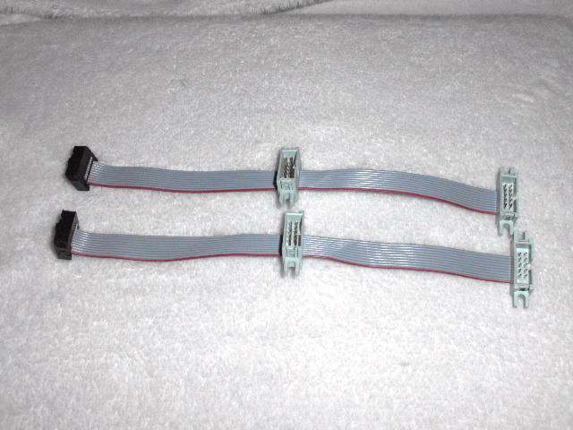
The easiest way to share the UEXT bus is the use of a ribbon cable with more three headers on it, like the one in the picture
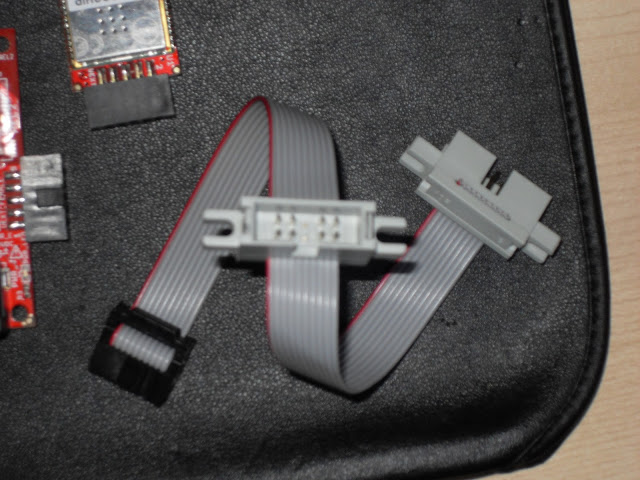
To share I2C and SPI is requested to remove from the header where the SPI (trasceiver) device will be connected the pins that are for I2C (and eventually USART), this lets extend only the needed wires to the transceiver.
This is applicable for :
- MOD-ENC28J60
- MOD-WIFI
In the picture below we have removed the pins that are used by I2C (SDA, SCK) and in that header will be installed the transceiver.
The I2C electrical standard uses open drain drivers to share the bus over multiple devices, the bus needs to be pulled up at one point and data transmission is achieved pulling low the bus.
A correct design needs only one pullup point (for both SDA and SCK) with resistor values that are based on the total capacitance (that depends on bus length and number of devices). Different pullups values affect the rising time and maximum values of the signal over the bus, have a look here for more details.
As general rule, a 4.7k resistors are used as pullups and some boards (like the Olimex one) may include those pullups, in Olimex case all boards have pullups on both master and slave side, some special care should be carried out for that.
Is important to note that the boards will work as are and no direct effect are seen also in case of improper connection, so lets have a detailed look.
The I2C master for Olimex's boards in Souliss are the ATmega based:
- Olimexino-328
- Olimexino-32U4
- AVR-T32U4
all these boards has 4.7k pullups connected to SDA and SCK lines on the UEXT connector. The Olimexinos has the pullups connected (on the 32U4 there is an SMD switch normally closed) rather the AVR-T32U4 has a normally open SMD switch, so the pullups are not connected.
From the slave point of view, boards like:
- MOD-IO
- MOD-IO2
- MOD-RGB
The MOD-IOs has two UEXT connector, the female one has pullups and the male hasn't. On the MOD-IO2 the pullups are connected via normally closed SMD switches. The MOD-RGB has only one UEXT and the pullups are always connected.
So, you should find the proper connection based on the used hardware. For example and AVR-T32U4 by default has disconnected pullups and has to be connected on the female UEXT of the MOD-IOs, is ok also a direct connection on the MOD-RGB.
For the Olimexino, by default the male connector of the MOD-IOs has to be used. Is more complicated the case of the MOD-RGB that theoretically shouldn't be used (for the Olimexino-32U4 the SMD switches can be opened to solve the problem) or precautions shall be observed as detailed below.
Having pullups on both ends has two major effect :
- Current loopback in the power supply (if the boards has different power source)
- Lower value of the overall pullup resistance
The former is caused if the boards are powered by two different supply (referred at internal DC/DC or linear voltage regulator), this problem can be solved using a common supply at the UEXT connector. Most of the UEXT boards like (MOD-IO2 and MOD-RGB) can supply power to the board via the UEXT it self.
The latter effect cannot be solved if more pullups are there, a lower resistance generally should not affect the I2C communication but may damage the SDA pins or cause reset of the board (an open drain without pullup resistance create a short once activated). In case of two devices with 4.7k pullups the overall will be near to half 2.35k that doesn't create over current.
The use of a common power supply is preferable, switches on the boards allow the sharing of the 3.3V supply over the UEXT cable. Out of the I2C pullups case, sharing of the supply allows the use of a single main AC/DC adapter.
Generally transceiver always get power supply via UEXT and hasn't a different power source, rather microcontroller boards can either give or receive supply via UEXT.
On the UEXT can be shared only the 3.3V and some boards many need higher supply for proper operation, these are:
- MOD-IO
- MOD-IO2
- MOD-RGB
The MOD-IOs needs 12V supply for the relay coil, rather the MOD-RGB needs 12V for driving the LEDs. In these cases there are two options:
- Power the UEXT board with 12V and sharing the 3.3V via UEXT to the microcontroller
- Power the boards with different supply
If powering with different supply be sure that 3.3V isn't shared via UEXT and there are no shared supply via bus pullups (like the I2C).