SoulissAPI
Souliss APIs let you program your Souliss nodes with different logics and communication paradigms in order to harvest sensor values and issue commands to actuators. The methods can be divided as follows:
- Setup/Init functions
- Read/receive functions
- Write/send functions
All logics are based on a common concept, there is an input area that is used to read the command. Whoever write on that area (a pushbutton connected to the board or to another board, an user interface, another node, ...) trigger an action, this is stored in the output area. The inputs are cleared once the action is executed.
To the user interface (like Android) only the outputs are available as feedback. All logics are grouped by type, 1n are lights and share (as much as possible) same commands values. For example, Typical 11 and 12 are lights, the 12 has AUTO mode to be used with a PIR sensor. The 14 is a pulsed output, to be used with electric gate (that needs only a pulse to open).
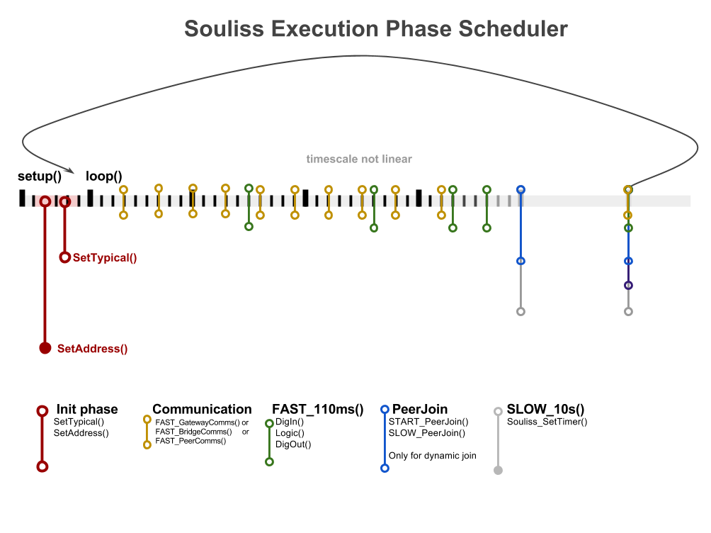
Souliss nodes, programmatically speaking, are Arduino sketches that run a loop() function. Inside the loop, a simple interval mechanism is provided, so that you can call API functions at pre-determined intervals:
In order to share the load on the microcontroller and avoid energy waste a simple scheduler is used in Souliss, this is build over two phases (slow and fast) that execute part of the code at regular time bases.
All the code included in the schedule at 50 ms will be executed at this rate, without preemption.
FAST_50ms() {
  ...
}
You can create multiple execution with the same periodic rate but with a different shift in time, use any value in the 0-255 range to select different shift to balance load between different phases. The SHIFT can be used only in the FAST group.
SHIFT_50ms(shift) {
  ...
}The Application Programming Interface are the methods used into an user sketch, those are grouped based on their scope and are defined as C Macro in the SpeakEasy:
- Network Setup
- Communication
- Publish/Subscribe
- Local I/O
Set the vNet network configuration parameters, in case of devices with multiple interfaces shall be multiple times, is not allowed the change of the network parameters out of the setup()
SetAddress(U16 addr, U16 subnetmask, U16 mysupernode);Define the vNet address relevant to device, this is not included in Souliss_SetAddress because only one address can be declared as Local also in case of boards with multiple interfaces.
If thi is missed, the board will not answer correctly to a Database Structure Request from Android or any other MaCaco interface.
SetAsGateway(U16 address);Define the vNet address of other nodes in the network that shall be monitored using this board as gateway, the address defined here will be used while building an event-based channel with other boards.
All nodes reported as remote will be available at Android or any other MaCaco interface. The node parameter shall be between 1 and the maximum number of nodes allowed in your configuration setup .
SetAsPeerNode(U16 address, U8 index);Define an IP address and relevant subnetmask and IP gateway, this set automatically also the vNet address of the node using the last byte of the IP address.
SetIPAddress(U8* ip_address, U8* subnet_mask, U8* ip_gateway);Is used in a network without fixed addresses in the Souliss network, shall be used with a Gateway and let it assign an address to peers. It doesn't set the IP address of the Gateway node, that must be set before the use of this method.
SetAddressingServer();Is used in a network without fixed addresses in the Souliss network, shall be used with Peer nodes to assign a temporary address while getting from the Gateway a final address to be stored in the EEPROM.
SetDynamicAddressing();It follows the SetDynamicAddressing(); and start the process to get an address from the Gateway.
GetAddress();Process all the communication relevant for a Gateway, this include also the process of communication channels defined with SetAsPeerNode and the retrieve of Typicals for the user interfaces.
Is a composite macro and doesn't need to be placed inside a PHASE.
FAST_GatewayComms();Process the communication and data routing/bridging in case of nodes with multiple communication interface.
Is a composite macro and doesn't need to be placed inside a PHASE.
FAST_BridgeComms();Process the communication for a standard Peer node.
Is a composite macro and doesn't need to be placed inside a PHASE.
FAST_PeerComms();Broadcast periodically the node addressing details till it get a subscription from a Gateway. Is also used to build dynamically the communication path between nodes.
Is a composite macro and doesn't need to be placed inside a PHASE.
START_PeerJoin()Broadcast periodically the node addressing details and is unrelated with the subscription state, useful to rebuild the subscription and communication paths in case of reboot of nodes.
Is a composite macro and doesn't need to be placed inside a PHASE, shall be located into the SLOW group.
SLOW_PeerJoin()Let a node act as a remote input for another node, it simply force a command into a peer node. It can be used to transfer a pushbutton from a node to a peer one.
RemoteInput(U16 addr, U8 slot, U8 command);As previous one, but transfer an array of commands and not a single one.
RemoteInputs(U16 addr, U8 firstslot, U8 *commands, U8 numberof);Build a network watchdog as a virtual chain of nodes, a token is passed from each node to the next one. If one node goes off, the next in the chain didn't receive the token and goes in alarm. If the node is in alarm, Watchdog returns the alarm_command.
Each node in the chain can go returns the alarm state and shall then send that to another node that has a sounder or any other external notification.
Is mandatory that all nodes in the chain share the same value for chain_slot.
Watchdog(U16 chain_address, U8 chain_slot, U8 alarm_command);Using this methods gives a communication path that is free from the SLOT and TYPICAL relation, more details in peer to peer communication.
Broadcast (a multicast option is available) a topic to other nodes, optionally data can be send together with a specific topic.
pblsh(topic);Is a trigger for any user code relevant to specific topic
sbscrb(topic);Read a value from a digital input pin and assign the value into the slot, is used to define the action (example Turn On Light) to a digital input.
The action is triggered on the HIGH value of the input pin, so is suggested to use a pull-down resistor in order to avoid false reading. This function, like all others input ones, act on the edge of the signal.
U8 DigIn(U8 pin, U8 value, U8 slot);As DigIn but acts on LOW value and needs a pull-up value.
U8 LowDigIn(U8 pin, U8 value, U8 slot);Detect the steady state of an input (like a pushbutton) with two different action (values) for HIGH and LOW state. Wiring shall force the input to HIGH or LOW and cannot be floating or pulled-down/up.
Can be used to convert a bistable push-button into an ON/OFF command.
U8 DigIn2State(U8 pin, U8 value_state_on, U8 value_state_off, U8 slot);Detect the edge of the signal on the HIGH value or if the inputs is forced HIGH for more than some seconds (see the code for details), a single pushbutton has two different actions based on single press or long press.
The pull-down resistor must be applied and tuned properly, too high resistor values may drive a false long press.
U8 DigInHold(U8 pin, U8 value_state1, U8 value_state2, U8 slot);This method recognize a single short and long press, keeping pressed the button will give just one execution of the value_state2, if you need to detect long press multiple time use:
U8 DigKeepHold(U8 pin, U8 value_state1, U8 value_state2, U8 slot);Similar to DigInHold, but controls two different slots.
Single press -> value_state1 -> slot1
Long press -> value_state2 -> slot2
U8 DigInHold2(U8 pin, U8 value_state1, U8 value_state2, U8 slot1, U8 slot2);As LowDigInHold but active on LOW input values. With single long press detection
U8 LowDigInHold(U8 pin, U8 value_state1, U8 value_state2, U8 slot);and multiple long press detection,
U8 LowDigKeepHold(U8 pin, U8 value_state1, U8 value_state2, U8 slot);Similar to DigInHold2, but active on LOW input values.
U8 LowDigInHold2(U8 pin, U8 value_state1, U8 value_state2, U8 slot1, U8 slot2);Force to HIGH value a digital output pin if a slot match a value, is used to assign an output pin to a logic.
DigOut(U8 pin, U8 value, U8 slot);Force to HIGH value a digital output pin if a slot match a value as bit-wise AND boolean operation, is used for a pin that needs to be activated for multiple value states.
nDigOut(U8 pin, U8 value, U8 slot);As DigOut, but drives the pin LOW when activated. In normal condition the output pin is at HIGH value, to avoid spurius activation at first boot you have to force the output register to an HIGH value before set the pin as output.
LowDigOut(U8 pin, U8 value, U8 slot);setup()
{
...
digitalWrite(pin, HIGH);
pinMode(pin, OUTPUT);
}As nDigOut, but drives the pin LOW when activated. In normal condition the output pin is at HIGH value.
nLowDigOut(U8 pin, U8 value, U8 slot);While the slot match the value the digital output pin will toggle once per execution cycle of the method. Can be used to flashing light or similar cases.
DigOutToggle(U8 pin, U8 value, U8 slot);These are same as Local I/O but doesn't act on the node itself, but on another node into the network. Compared with the relevant Local I/O ones require the address of the target node as parameter.
Read a value from a digital input pin and assign the value into the slot of the addr node, is used to define the action (example Turn On Light) to a digital input.
The action is triggered on the HIGH value of the input pin, so is suggested to use a pull-down resistor in order to avoid false reading. This function, like all others input ones, act on the edge of the signal. This is equivalent to DigIn but acts on a different node of the network.
U8 RemoteDigIn(U8 pin, U8 value, U16 addr, U8 slot);U8 RemoteLowDigIn(U8 pin, U8 value, U16 addr, U8 slot);U8 RemoteDigIn2State(U8 pin, U8 value_state_on, U8 value_state_off, U16 addr, U8 slot);U8 RemoteLowDigIn2State(U8 pin, U8 value_state_on, U8 value_state_off, U16 addr, U8 slot);U8 RemoteDigInHold(U8 pin, U8 value, U8 value_hold, U16 addr, U8 slot);U8 RemoteLowDigInHold(U8 pin, U8 value, U8 value_hold, U16 addr, U8 slot);You can have direct access at the memory area using mInput(slot), mOutput(slot), mOutputAsFloat(slot) and mTypical(slot) this allow direct handling of data and interaction with typicals. If you are using a persistance use pOutput(node,slot) , pOutputAsFloat(node,slot) and pTypical(node,slot).