Use RCSwitch
The RF Power Sockets are one of the fast and easy way to control an electrical device without be involved in wiring and cabling activities (and either being far from your line 120/220 V), these device shall be placed in between your socket and the device that you are willing to control. These come with a remote control device that allow you to turn them ON and OFF.
Is basically a quick way to get ON/OFF control of simply electrical appliance. If instead of use the original remote control you use a Souliss node, then your RF Sockets comes automatically into the net, including Android control. The RF stands for Radio Frequency, a simple burst modulated at 315 or 433 MHz allow to control the sockets, so we need a relevant RF transmitter to connect with an Arduino node with Ethernet facility.
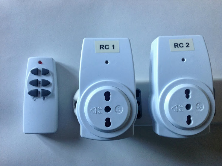
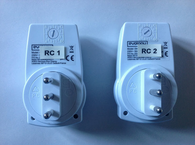
Each RF Socket has an address that can be set via rotary or DIP switches that are located on the back, once inserted in your home socket the RF ones will goes ON and OFF from your remote control.
The RCSwitch library runs on Arduino devices and using a cheap RF 315 or 433 MHz transmitter, is an easy way to send a control frame to the sockets. Most of the RF Sockets available on the market use the same coding, these are stored into RCSwitch, so you can control mostly all RF Sockets on the market, no matter the brand.
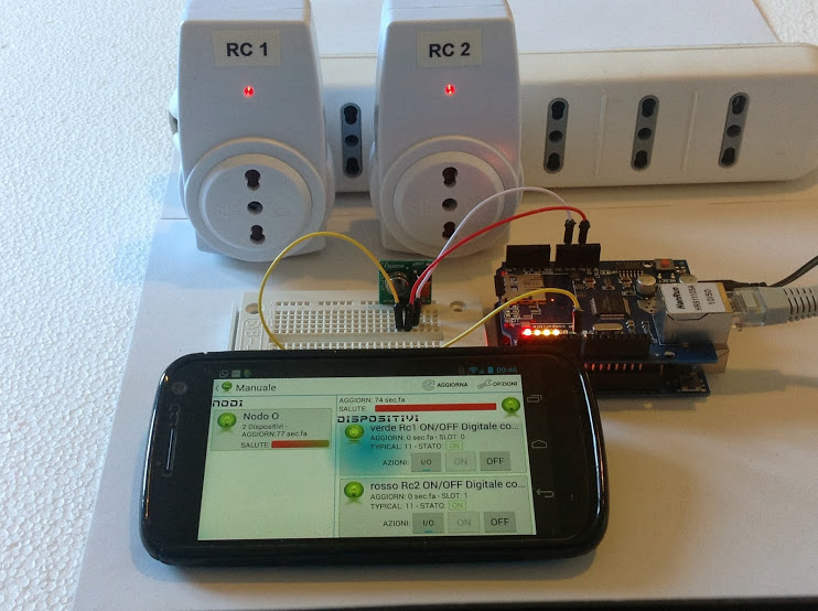
On the project page of RCSwitch you can found the instruction to connect your RF transmitter with an Arduino compatible device, you can even change the transmit pin but ensure that is not used by other devices. If you don't know how, just ask on the Community.
At this time you should be able to control your sockets via Arduino, the next step is to integrate this in Souliss. If quite straightforward, just need to link the output of Souliss to RCSwitch send.
This code is a simple ON/OFF switch example and just adds some code to integrate with RCSwitch, we will shown the adding and later the full code:
Define an RCSwitch object, this will be used to send control frames to the sockets
#include <RCSwitch.h>

RCSwitch mySwitch = RCSwitch();

// Send an output command to the socket
#define RcDigOut(code1, code2, value, slot) Souliss_RcDigOut(code1, code2, value, memory_map, slot)
void Souliss_RcDigOut(U8 code1, U8 code2, U8 value, U8 *memory_map, U8 slot)
{
	// If output is active switch on the pin, else off
	if(memory_map[MaCaco_OUT_s + slot] == value)
		 mySwitch.switchOn(code1,code2);
	else
		mySwitch.switchOff(code1, code2);
}
In the setup() is declared the pin where the transmitter is connected, 7 in this example
void setup()
{

...

// Declare the pin where the transmitter is connected
mySwitch.enableTransmit(7);
}
In the loop() if there is a new event (data change) a command is sent out
// Send an output to the socket if there is a data change
if(isTrigger()) {
	RcDigOut1(1, 1, Souliss_T1n_Coil, LIGHT1_NODE1);
	RcDigOut2(1, 2, Souliss_T1n_Coil, LIGHT2_NODE1);
}
These socket are pretty cheap piece of hardware and doesn't support any readback. So, Souliss cannot read the state of the RF socket but knows the last command that was sent out. This means that you can no longer use the old-fashion remote control, because Souliss will not be notified of the change in the state of the socket.
So, the code send out periodically a command to align the socket. This will guarantee that in case of missed command or power lost, the socket get back to the desired state in few minutes, in all the other cases, the socket goes to the state in few seconds.
See it in action, YouTube video
Following the complete code, you can run it directly
// Configure the framework
#include "bconf/StandardArduino.h"          // Use a standard Arduino
#include "conf/ethW5100.h"                  // Ethernet through Wiznet W5100
#include "conf/Gateway.h"                   // The main node is the Gateway

...

#include <RCSwitch.h>

// Define the network configuration according to your router settings
uint8_t ip_address[4]  = {192, 168, 1, 77};
uint8_t subnet_mask[4] = {255, 255, 255, 0};
uint8_t ip_gateway[4]  = {192, 168, 1, 1};
#define Gateway_address 77
#define Peer_address    78
#define myvNet_address  ip_address[3]       // The last byte of the IP address (77) is also the vNet address
#define myvNet_subnet   0xFF00
#define myvNet_supern   Gateway_address

#define LIGHT1_NODE1    0
#define LIGHT2_NODE1    1


RCSwitch mySwitch = RCSwitch();

// Send an output command to the socket
#define RcDigOut(code1, code2, value, slot) Souliss_RcDigOut(code1, code2, value, memory_map, slot)
void Souliss_RcDigOut(U8 code1, U8 code2, U8 value, U8 *memory_map, U8 slot)
{
	// If output is active switch on the pin, else off
	if(memory_map[MaCaco_OUT_s + slot] == value)
		 mySwitch.switchOn(code1,code2);
	else
		mySwitch.switchOff(code1, code2);
}

void setup()
{
    Initialize();

    // Set network parameters
    Souliss_SetIPAddress(ip_address, subnet_mask, ip_gateway);
    SetAsGateway(myvNet_address);     // Set this node as gateway for SoulissApp

    // Set the typical logic to handle the lights
    Set_T11(LIGHT1_NODE1);
    Set_T11(LIGHT2_NODE1);

    // Define inputs, outputs pins
    pinMode(2, INPUT);                // Hardware pulldown required
    pinMode(3, INPUT);                // Hardware pulldown required
    pinMode(7, OUTPUT);               // trasmettitore 433Mhz


     // Declare the pin where the transmitter is connected
     mySwitch.enableTransmit(7);

}

void loop()
{
    // Here we start to play
    EXECUTEFAST() {
        UPDATEFAST();

        // Read every 510ms the input state and send it to the other board
        FAST_510ms() {
           // Use Pin2 as ON/OFF command
           DigIn(2, Souliss_T1n_ToggleCmd, LIGHT1_NODE1);

           // Use Pin3 as ON/OFF command
           DigIn(3, Souliss_T1n_ToggleCmd, LIGHT2_NODE1);

           // Execute the logic
           Logic_T11(LIGHT1_NODE1);
           Logic_T11(LIGHT2_NODE1);

           // Send an output to the socket if there is a data change
           if(isTrigger()) {
             RcDigOut(1, 1, Souliss_T1n_Coil, LIGHT1_NODE1);
             RcDigOut(1, 2, Souliss_T1n_Coil, LIGHT2_NODE1);
            }
        }

        // Here we handle here the communication
        FAST_GatewayComms();


}

EXECUTESLOW() {
        UPDATESLOW();

        SLOW_10s() {        // We handle the light timer with a 10 seconds base time
            Timer_T11(LIGHT1_NODE1);
            Timer_T11(LIGHT2_NODE1);
        }

        SLOW_70s()  {
             RcDigOut(1, 2, Souliss_T1n_Coil, LIGHT1_NODE1);
             RcDigOut(1, 2, Souliss_T1n_Coil, LIGHT2_NODE1);
        }
    }
}