Howto: CC3D flight controller, minimOSD , telemetry and GPS for fixed wing
-
Features
-
What is needed
-
Flashing iNAV firmware to CC3D.
-
Basic settings
Flight controller orientation.
Port settings
Configuration
Failsafe
Transmitter setup
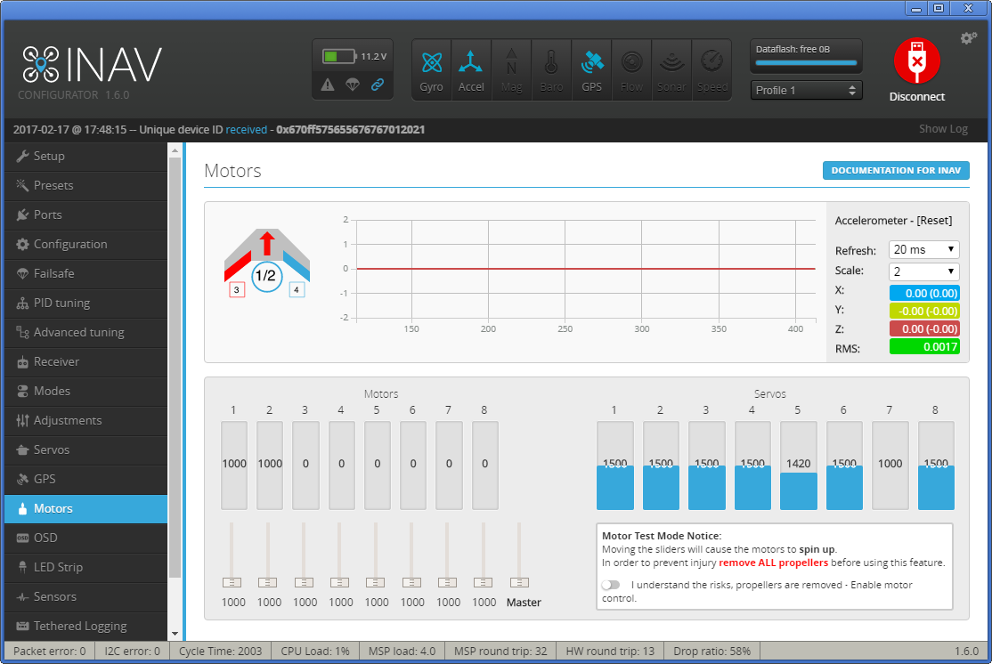
Motors
Servo setup
Recommended power layout
OSD setup
- Stabilization (Angle, Horizon modes)
- RTH (baro and mag are not needed for fixed wing)
- Waypoint missions (with EZGUI android apk).
- Battery monitoring
- RSSI monitoring
- Failsafe
- Telemetry
- etc
- Flight controller (one from the list, this guide shows how to setup CC3D)
- OSD (minimOSD or any other that supports Cleanflight)
- RX with telemetry support (just in case you want also telemetry). And a telemetry capable ground system.
- GPS receiver (any that supports at least 5Hz update)
- FPV hardware, airframe, RC
First you need to download a precompiled firmware for the board here. Select one of the releases precompiled for CC3D:
- inav_x.x.x_CC3D.hex for PWM receiver
- inav_x.x.x_CC3D_PPM1.hex for PPM receiver
Next, you can check numerous guides how to flash CC3D with third party firmware (Attention, you'll need a FTDI adapter for the purpose). Of course you need to specify the previously downloaded firmware for the flashing. For now, if you have servos, it is not advisable to flash with them attached, because there is high frequency sent with default configuration, and you can burn them (the way -for now- is flash, configure plane and then attach servos).
It is done using Ports tab 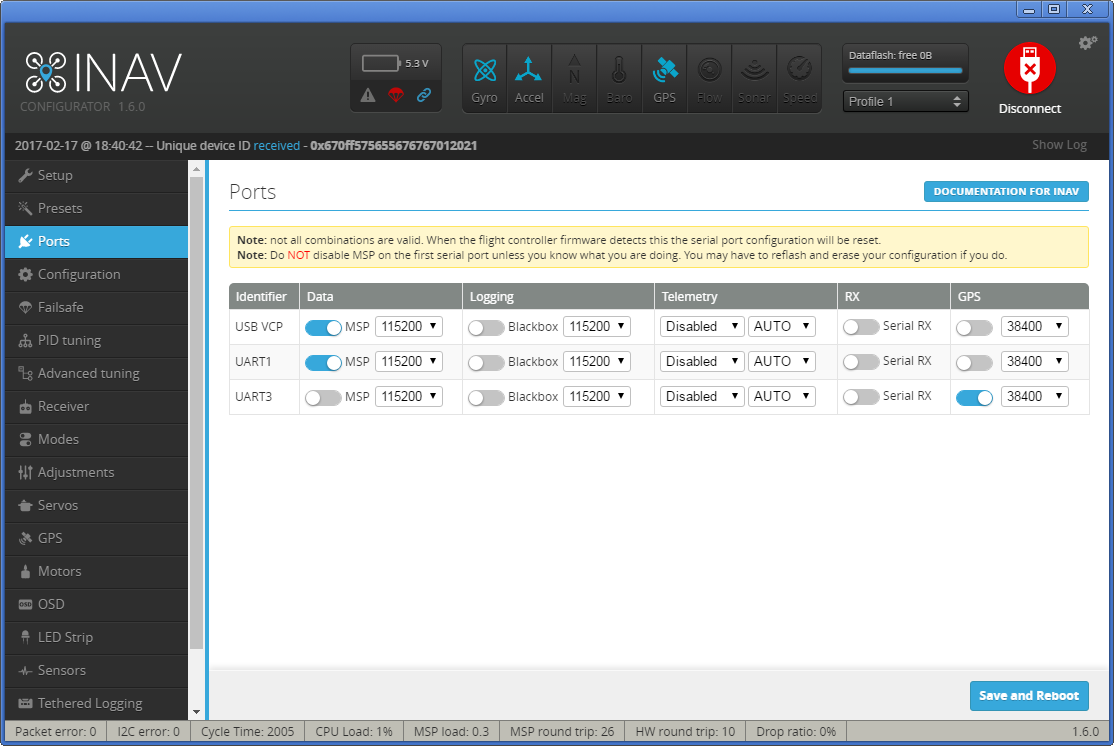
- UART1 - leave default value. You'll connect here either OSD or FTDI to setup the FC. If you want telemetry select it in Inav configurator, so you can have telemetry when the aircraft is armed. In this case, your OSD should be capable to read LTM, in order to mantain working OSD and telemetry at the same time. You have to connect the TX line from CC3D to both OSD and RX telemetry capable receiver (as openlrsng systems). MWOSD can read both MSP and LTM telemetry.
- UART3 - for GPS. Switch on the option and select the correct port speed (38400 or 57600). Please pay attention that when using a ublox GPS receiver family 6-8 you don't need to make any configurations in the u-center. The flight controller under iNAV will do everything what is needed.
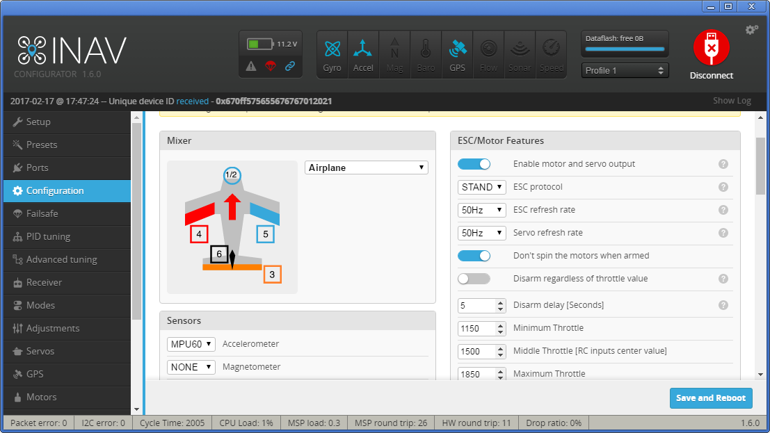
On the Configuration tab in the Mixer group select the Airplane or Flying Wing depending on the airframe you are using.
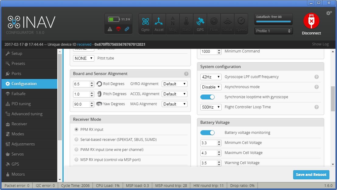
After the calibration is done you may select the sutable board orientation
Now you are ready to connect your hardware according to the schemes:
Parallel PWM Receiver (click here to see the real hardware photo)

PPM Receiver
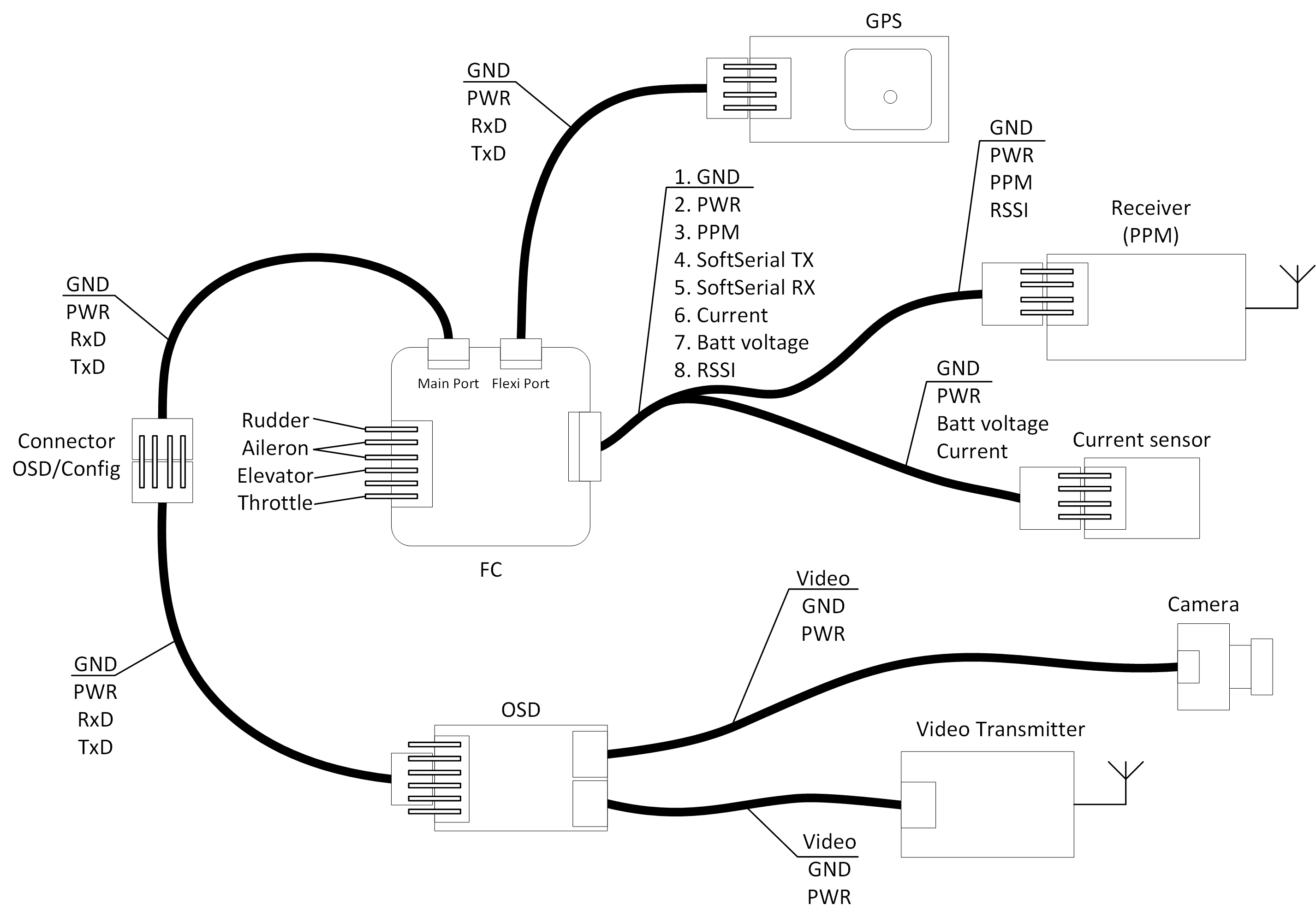
Of course, according to the receiver used you need to use the aproppriate firmware for CC3D - inav_1.6.0_CC3D.hex for parallel PWM or inav_1.6.0_CC3D_PPM1.hex PPM receiver. For more information about CC3D pinout check the CC3D page
I usually don't like the motor rotation on arm, so I switch on the "Don't spin motors when armed" feature.
The new INAV firmware has all PWM outputs disable until you switch on the "Enable motor and servo output"
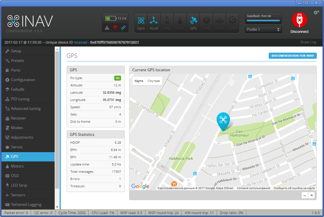
Switch on the GPS feature, and select the protocol.
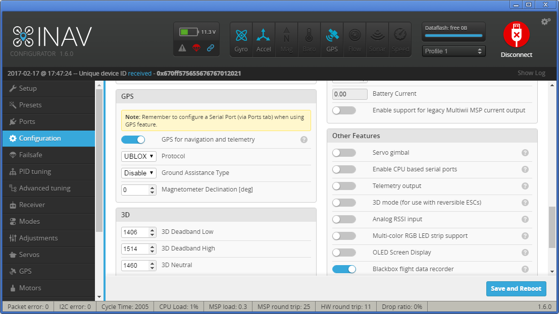
If your GPS receiver have enough satellites visible you'll be able to check the 3D fix in GPS tab ![3D fix] (http://s8.hostingkartinok.com/uploads/images/2017/02/2db676b5f03d436480919b1cbc945fb5.png)
By default INAV won't arm without GPS fix if the GPS feature is ON. To disable it use CLI: "set nav_extra_arming_safety = OFF". And it is highly recomended to switch it back ON before real flights.
If your receiver connection is other than Parallel PWM Receiver, then you'll be able to setup battery voltage, current, RSSI monitoring. It is very userful. So IMHO a PPM is a must for CC3D FC.
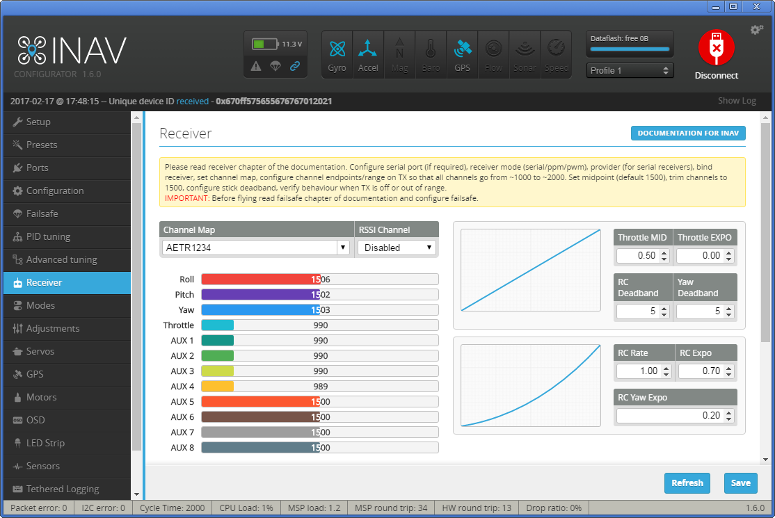
On the Receiver tab set up the channel order and their correspondence to TX sticks movements.
On the Modes tab set up the flight modes according to the position of the AUX channels. For example, if you have a 3pos switch for the AUX1 you can get at minimum the following:
- minimum channel value - do not select any mode - only gyros will work. The hand launch take off in this mode is excellent.
- middle value - Angle or Horizon.
- maximum value - RTH. Automatic return home.
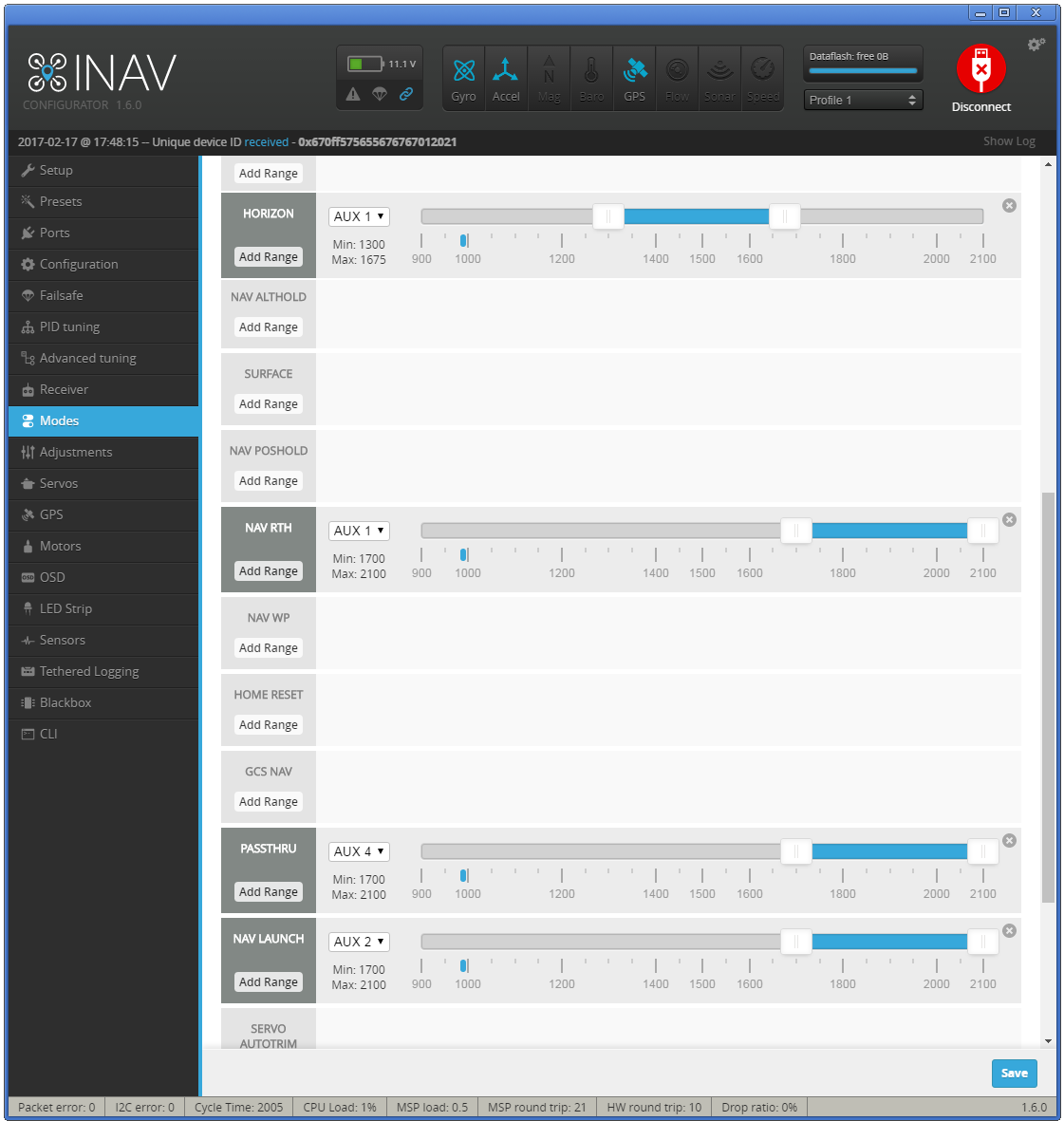
Check this link for RTH failsafe
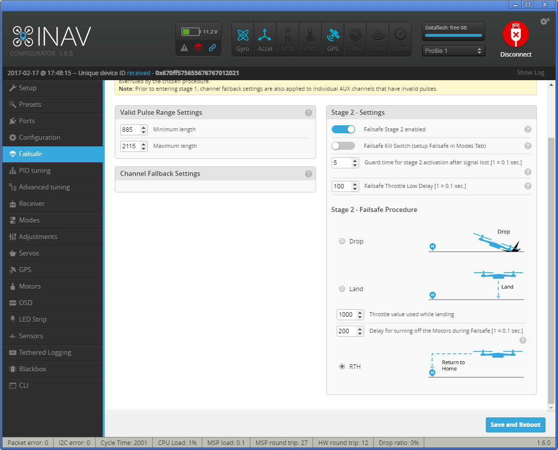
Starting from iNav 1.6 the Filesafe feature is very transparent and clear. For the failsafe to work you'll need:
- Setup the receiver output no signal when your TX is off
- OR assign the Failsafe mode to one of the channels and force it to trigger when your TX is off
Set the desired Failsafe behavior. I prefer RTH.
###Telemetry
Connect your TX line and configure FC as explained above. Nowadays you can use several telemetry systems as mwptools, EZGUI, LTM Telemetry OLED and possibly others. The USART port can be shared with a OSD or used only for one of both features. For example, you can fly FPV w/o telemetry (just in your googles) or fly thermal soaring 3rd view w/o OSD. Or have both. Amazing you can do this with a simple cc3d, isnt it?.
###Transmitter setup
You should adjust (normal or reverse) on your transmitter so sticks correspond to below:
In reciever tab:
- Throttle stick push away - increased value
- Yaw (Rudder) stick right - increased value
- Pitch (Elevator) stick push away - increased value
- Roll (Ailerons) stick right - increased value
Also use subtrim to get center value of 1500us and use travel adjustment to get at lowest value 1000us and highest 2000us when moving sticks.
After this follow to the Motors tab, rock your plane and notice what levels are moving depending on PITCH, ROLL and YAW angles. You can remember it or write it down. ROLL - 4,5; PITCH - 3, YAW - 6.
Turn on your transmitter, switch to the Angle or Horizon flight mode and follow the Servos tab.
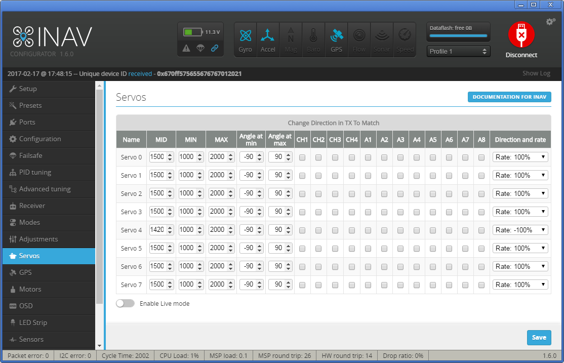
Here you need to be very attentive. In this tab you set up endpoints, neutral, rates and reverse for stabilization modes. Servo numbering in the tab starts from 0!
For the Elevator, tilt the plane's tail down, and the Elevator should go down. If the elevator goes up, then you need to set the Rate (the right-most drop down list) Servo 2 with negative sign.
Tilt the left wing down. Left Aileron should go down and right one should go up. If it is not so, then put negative Rate values for Servo 3 and Servo 4 (if your ailerons are connected by means of Y-cable, than you can change the settings for only one Servo or connect the Y-cable to other Servo out).
Turn the tail to the left, and the Rudder should go to the left. Otherwise switch the Servo 5 Rate to negative.
After this stick movement should also move servos the correct way. (General rules: Elevator stick down - elevator goes up, Aileron stick to the left - left aileron is up, right aileron is down, Rudder stick to the left, rudder goes to the left)
Attention! all the endpoints, neutrals, trimmers should be done on this tab, not in transmitter!
To prevent brownout its wise to power servos with one BEC and the flight controller + other equipment with another BEC.
This is one way to accomplish it:
Glued a new row of pins onto the case of the flightcontroller, the must be connected together. (See the bottom of pins)
All servos and ESC is connected to flightcontroller, except positive wire which goes to the new row. (This line gets its power from the BEC in the ESC)
Another external BEC is connected at random positive and negativ pin on flight controller to power it, the receiver and GPS.
This way if one servo get stuck and draws alot of amps you shouldnt risk your flight system to power down.


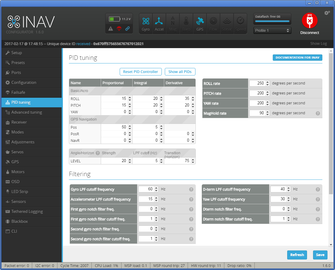
The default PID settings that are set using Presets tab are a good starting point but usually you may need to chnge them if you want yor plane to fly really stable.
Here are my PIFF settings for a small 800mm flying wing - EPP Rainbow.
DigitalEntity wrote about the PIFF controller setup procedure the following, I have nothing to add:
If you have inflight adjustments - this will be easier for you. I tuned like this:
-
Fly ANGLE mode, LOS, calm day. Started with these PIFFs: P=5, I=10, D/FF = 20
-
Give hard roll command, watch how plane executes it. It should be smooth from start to finish, without (or with minimal) oscillation at the end of the roll, without much wobble. If it oscillates at the end of maneuver - reduce FF; if it starts fast, then slows down and after a moment pushes it further - that's indication of too low FF
-
Repeat for pitch
-
I dialed up FF as much as possible until I started to get oscillations at the end of maneuver and backed about 20%
-
If it doesn't reach commanded angle - increase I-gain (best verifiable with OSD indication for roll/pitch angles
-
Wait for some wind (to get some turbulence)
-
Dial up P to fight turbulence better. In ANGLE mode I+FF will keep aircraft nice and level, but P will improve turbulence handling. WARNING - increasing P will cause much more active servos and reduce their life expectancy.
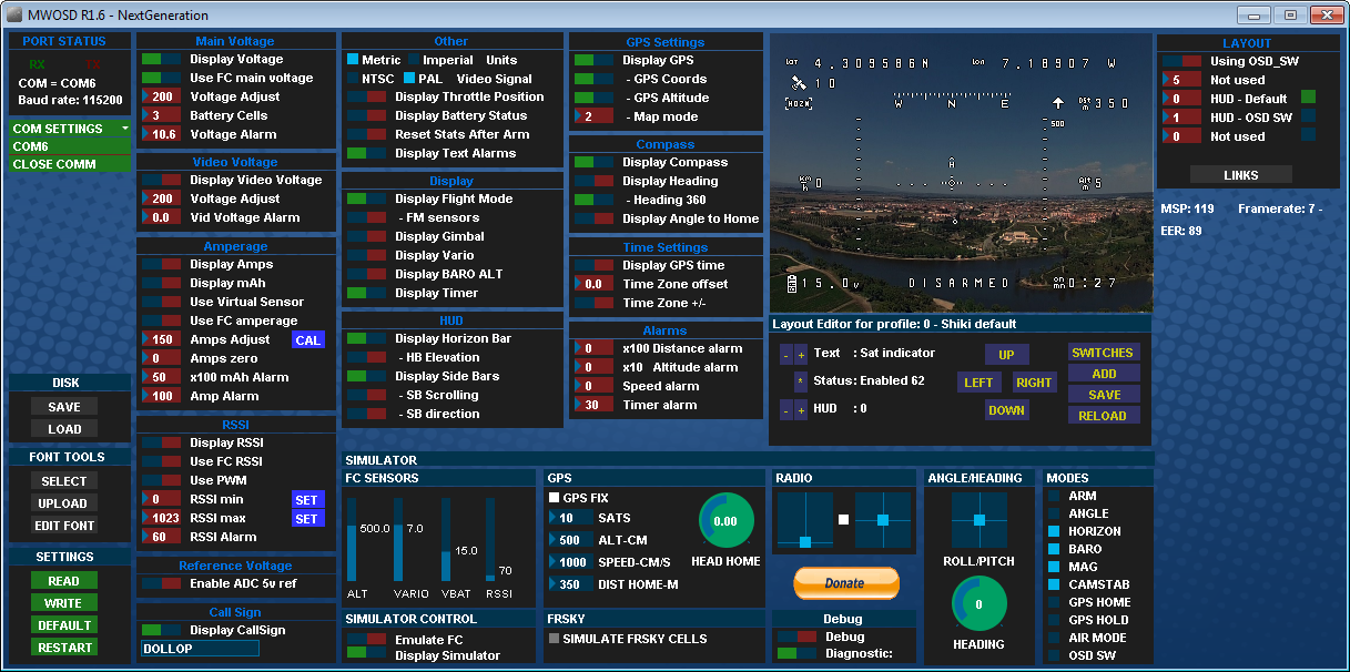
I prefer using MW-OSD. It supports many protocols and also has native support of iNAV. Say you have a minimOSD or micro minimOSD. So first you need to upload MWOSD firmware to your minimOSD. You can find pretty straight forward install guide following the link. As usual you use Arduino IDE for global OSD config. All changes are done in the Config.h file. In our case we need to leave uncommented the following lines:
OSD HARDWARE settings:
#define MINIMOSD
CONTROLLER SOFTWARE
#define iNAV
AIRCRAFT/INSTALLATION TYPE settings
#define FIXEDWING
Usualy it is enough.
You may enable also rather helpful '#define MAPMODE' under FEATURES that allows you to see the map indication of relative positions of home and aircraft.
Configure config.h allowing LTM if you want to share USART1 with your telemetry system, as explained above.
All other settings are done in MWOSD configurator. Everything you need is to select the font you like, OSD indicators' positions. As iNAV takes care of voltage/current/rssi monitoring you'll need to ask the MWOSD to take these values from the FC (see the fig)
The screenshot of the MWOSD configuration is shown below:
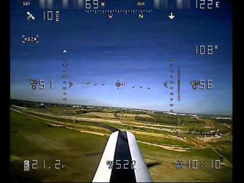
Watch this demo video of the iNAV flight and RTH function:
Good luck!