wiring can bus
Separate the MCU's CAN signals from the two-wire physical bus.
Applies to: Conventional high-speed two-wire CAN. This is not a low-speed fault-tolerant, single-wire, OBD connector or automotive harness pinout.
Building a documented CAN network between development boards, robots or instruments.
CAN controllers handle messages and arbitration; transceivers connect those controllers to CANH/CANL.
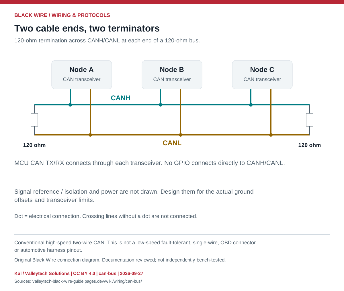
| Connection | Meaning | Check |
|---|---|---|
| MCU TX / RX | Controller-to-transceiver logic | I/O supply compatibility |
| CANH / CANL | Twisted differential pair | Do not swap or attach directly to GPIO |
| 120 ohm at each end | End termination | Include terminators already fitted |
| Reference / isolation | Keep common-mode within limits | Follow the transceiver and system design |
- Keep the trunk linear and stubs short; choose cable length and rate together.
- Match bit timing; CAN FD needs compatible controllers and transceivers.
- Use another active receiving node for acknowledgement during a normal transmit test.
- CAN does not define one universal connector or wire-color scheme.
- With all power removed, two simple 120-ohm end resistors in parallel give about 60 ohms; this check alone cannot prove correct wiring.
This is a general interface guide; match your own hardware documentation.
Source documents inspected; independent electrical and bench review pending. Reviewed 2026-09-27.
- Texas Instruments: CAN physical layer, SLLA270 — Figures 6, 8 and 9: transceivers and end termination; connector scope; checked 2026-09-27
Original writing and diagram by Kal / Valleytech Solutions, CC BY 4.0. Manufacturer artwork and documentation retain their own rights.
CC BY 4.0 · SHA-256: 9a5f07b44175ec5e39458e8a822a1102ab9dcb43d2f373b339db43254366d725