wiring rs232 interface
Understand why an RS-232 port cannot connect straight to a logic-level UART.
Applies to: Signal path only. Choose a transceiver and supply circuit from its datasheet; DTE/DCE roles determine the cable wiring.
Interfacing a microcontroller with an instrument or legacy serial port.
The transceiver translates the electrical levels and polarity while the UART handles byte framing.
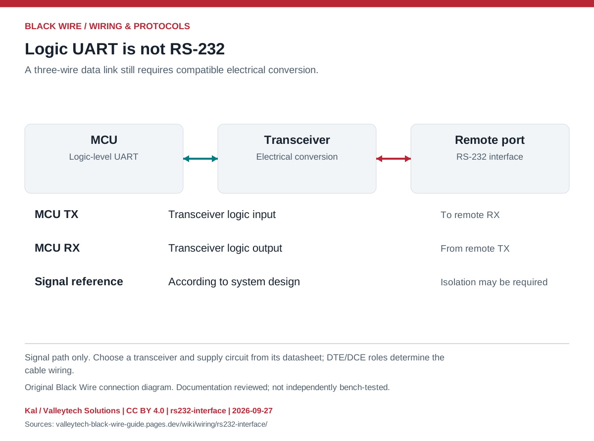
| Layer | Job | Check |
|---|---|---|
| MCU UART | TX / RX logic | I/O voltage |
| RS-232 transceiver | Translate electrical levels | Supply, capacitors, channel direction |
| Serial cable | Connect endpoints | DTE/DCE and pin-numbered connector views |
- Identify both port roles and whether hardware flow control is required.
- Use the equipment pinouts to select a straight-through or null-modem cable.
- Match baud and framing after checking the electrical connection.
- Never apply an RS-232 signal directly to a GPIO input.
- A DE9 shell does not prove a port is RS-232; similar connectors carry CAN and other interfaces.
This is a general interface guide; match your own hardware documentation.
Source documents inspected; independent electrical and bench review pending. Reviewed 2026-09-27.
- Analog Devices: RS-232 fundamentals — DTE / DCE and RS-232 electrical interface; checked 2026-09-27
Original writing and diagram by Kal / Valleytech Solutions, CC BY 4.0. Manufacturer artwork and documentation retain their own rights.
CC BY 4.0 · SHA-256: 0d951725f1935e801a58f2d87f3a6dbfbfff5a0aed8832e7b36638265f68aa78