wiring pn532 v3 modes
Select UART, I2C or SPI before following that interface's wiring diagram.
Applies to: V3 manual revision B, 2013-11-05. Switch settings are not transferable to V4, MINI, USB or unbranded boards.
Identifying a documented ELECHOUSE V3 module for an NFC prototype.
The same header labels can have different roles in different modes.
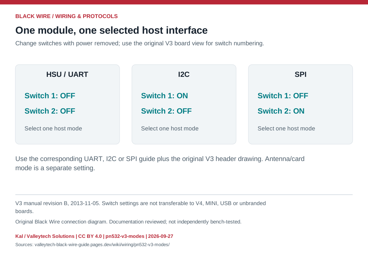
| Host mode | Switch 1 | Switch 2 |
|---|---|---|
| HSU / UART | OFF | OFF |
| I2C | ON | OFF |
| SPI | OFF | ON |
- Identify the V3 board and numbered switches from the original reference.
- Choose one interface, power-cycle after changing it, and use the corresponding library configuration.
- Follow the exact header map and verify supply and I/O levels separately.
- This guide does not approve the legacy manual's broad voltage-tolerance wording for every pin.
- NFC radio/card mode is separate from the UART/I2C/SPI host mode.
- PN532 NFC RFID module V3 — original images and datasheets
Source documents inspected; independent electrical and bench review pending. Reviewed 2026-09-27.
- ELECHOUSE PN532 V3 user manual, revision B — Pages 3-5: interface switches and headers; not valid for other PN532 boards; checked 2026-09-27
- NXP: PN532/C1 datasheet — Host interfaces and supported operating modes; checked 2026-09-27
Original writing and diagram by Kal / Valleytech Solutions, CC BY 4.0. Manufacturer artwork and documentation retain their own rights.
CC BY 4.0 · SHA-256: 39f47978d840c0ee28319db3d0e35ee1ee9d9997b3b1df22eced94798e127ff4