wiring i2c bus
Wire SDA and SCL for compatible sensors on a short local bus.
Applies to: Ordinary open-drain I2C. Connector-branded systems still require their own pinout and voltage check.
Connecting addressed peripherals while using few MCU pins.
Devices share data and clock lines and release them high through pull-up resistors.
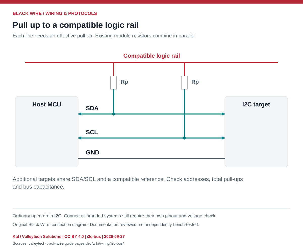
| Signal | Connection | Purpose |
|---|---|---|
| SDA | SDA on each device | Bidirectional data |
| SCL | SCL on each device | Clock; a target may stretch it |
| GND | Common reference | Non-isolated example |
| Pull-up rail | Compatible with every I/O | Not automatically the module power input |
- Check addresses for collisions and configure the documented bus speed.
- Determine the total pull-up resistance from all attached boards.
- Choose resistance using rise-time, capacitance and sink-current limits; 4.7 kohm is not universal.
- A 5 V pull-up can damage a non-tolerant 3.3 V input.
- Do not cross SDA and SCL. A detected address alone does not prove the correct device or power configuration.
This is a general interface guide; match your own hardware documentation.
Source documents inspected; independent electrical and bench review pending. Reviewed 2026-09-27.
- NXP: I2C specification, UM10204 — SDA/SCL, open-drain bus, addressing and pull-up sizing; checked 2026-09-27
Original writing and diagram by Kal / Valleytech Solutions, CC BY 4.0. Manufacturer artwork and documentation retain their own rights.
CC BY 4.0 · SHA-256: a7b801ab586b24a37d9650a55c6f8fcb29dd7ae65d3d572c80e040b30eff0dce