wiring telephone jacks
Recognize telephone connector families and a documented screw-terminal conversion.
Applies to: The conversion below is for the cited Leviton G/R/Y/B telephone wallplates. Handsets, digital PBX ports and country-specific cords may differ.
Identifying an analog telephone wall jack and its pair labels.
Connector contact count and service wiring are different things: RJ11 is one line, RJ14 two, and RJ25 three.
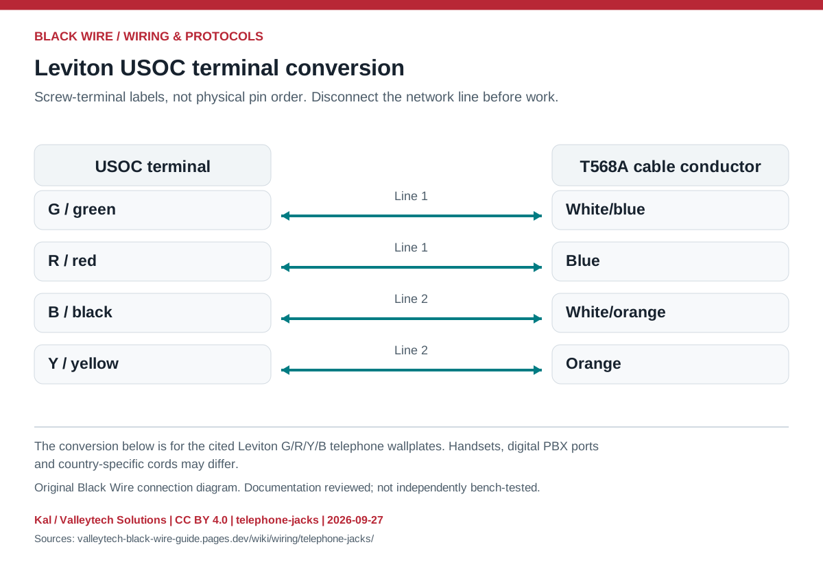
| USOC terminal | T568A conductor | T568B conductor |
|---|---|---|
| G / green | White/blue | White/blue |
| R / red | Blue | Blue |
| B / black | White/orange | White/green |
| Y / yellow | Orange | Green |
- Record existing terminal labels and identify the service before changing wiring.
- Use the matching manufacturer's terminal map and check cable continuity while disconnected.
- A live telephone line is not a GPIO-level signal; never connect it directly to a microcontroller.
- A telephone plug fitting a larger socket does not establish electrical compatibility.
This is a general interface guide; match your own hardware documentation.
Source documents inspected; independent electrical and bench review pending. Reviewed 2026-09-27.
- Leviton telephone wallplates, PK-93298-10-02-0H — Page 1: USOC to T568A/B conversion; G/R/Y/B screw terminals; checked 2026-09-27
- Fluke Networks: RJ connector naming — RJ11 / RJ14 / RJ25 versus modular connector contact counts; checked 2026-09-27
Original writing and diagram by Kal / Valleytech Solutions, CC BY 4.0. Manufacturer artwork and documentation retain their own rights.
CC BY 4.0 · SHA-256: bdb643ded276240844dc5936f273eb241bd49f47fc08b5c36ddbc7c74d637b76